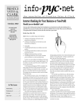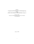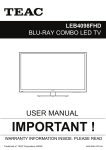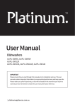
1
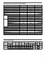
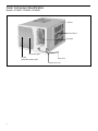
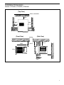
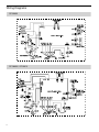
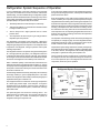
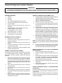
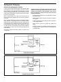
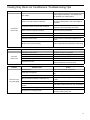
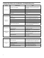
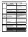
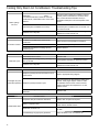
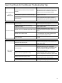
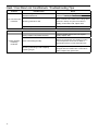
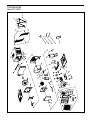
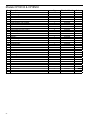
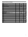
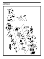
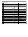
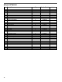
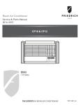
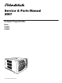
Service & Parts Manual
2007
Compact Programmable
Models
CP14N10
CP18N30
CP24N30
CP-14-18-24-Svc-Prts-07 (3-07)
Table of Contents
Performance Data ........................................................................................................................................................................ 3
Outer Component Identification ................................................................................................................................................... 4
Installation Dimensions ................................................................................................................................................................ 5
Wiring Diagrams ........................................................................................................................................................................... 6
Functional Component Definitions ...............................................................................................................................................7
Refrigeration System Sequence of Operation ............................................................................................................................ 8
Sealed Refrigeration System Repairs .................................................................................................................................... 9-12
Troubleshooting ..................................................................................................................................................................... 13-18
Part Diagrams and Part Lists................................................................................................................................................19-23
Warranty ..................................................................................................................................................................................... 24
The information contained in this manual is intended for use by a qualified service technician who is familiar
with the safety procedures required in installation and repair, and who is equipped with the proper tools and test
instruments.
Installation or repairs made by unqualified persons can result in hazards subjecting the unqualified person making
such repairs to the risk of injury or electrical shock which can be serious or even fatal not only to them, but also
to persons being served by the equipment.
If you install or perform service on equipment, you must assume responsibility for any bodily injury or property
damage which may result to you or others. Friedrich Air Conditioning Company will not be responsible for any
injury or property damage arising from improper installation, service, and/or service procedures.
2
Specifications and Technical Parameters
Model
CP14N10
CP18N30
Function
COOLING
COOLING
COOLING
115V ~
230/208V~
230/208V~
Rated Voltage
CP24N30
Rated Frequency
60Hz
60Hz
60Hz
Total Capacity (Btu/h)
14000
18000/17600
23500/23100
Power Input (W)
1430
1850/1810
2740/2710
Rated Input (W)
1540
2478
3538
15
12.57
18.09
Air Flow Volume (CFM) (H)
458.8
458.8
617.6
Dehumidifying Volume (pints/h)
3.38
4.65
8.46
EER / C.O.P BTU/W.H)
9.8
9.7/9.7
8.6/8.5
Rated Current (A)
Energy Class
Fan Type-Piece
Diameter-Length (inch)
Indoor Side
Evaporator
Pipe Diameter (inch)
Coil length (l) x height (H) x coil width (L)
Compressor Type
/
/
/
Centrifugal flow fan – 1
Centrifugal flow fan – 1
Centrifugal flow fan – 1
φ7.93 X 4.31
φ7.93 X 4.31
φ8.82 X 4.31
Aluminum fin-copper tube
Aluminum fin-copper tube
Aluminum fin-copper tube
φ0.276
φ0.276
φ0.276
16.61 X 15 X 1
16.61 X 15 X 1
16.61 X 15 X 1
ROTARY
ROTARY
ROTARY
58
42
56
10.9
7.45
11.7/11.0
2425/2480
L.R.A. (A)
Compressor RLA(A)
Compressor Power Input(W)
Outdoor Side
Overload Protector
Working Temp Range (ºF)
Condenser
Fan Type-Piece
Fan Diameter (inch)
Fan Motor Speed (rpm) (H/M/L)
1182
1700
MRA13425-12007
MRA98982-9200
Built in
50º-115º
50º-115º
50º-115º
Aluminum fin-copper tube
Aluminum fin-copper tube
Aluminum fin-copper tube
Axial fan –1
Axial fan –1
Axial fan –1
φ15.59
φ15.59
φ15.59
900/780/730
900/780/730
1000/900/800
Output of Fan Motor (W)
Fan Motor RLA(A)
Fan Motor Capacitor (uF)
200
200
190
3
1.45
1.35
15 MFD
7 MFD
7 MFD
Permissible Excessive Operating Pressure for the Discharge Side (Psig)
300
300
300
Permissible Excessive Operating Pressure for the Suction Side (Psig)
150
150
150
Dimension (H/W/D)( inch)
16.85 x 25.98 x 28.46
16.85 x 25.98 x 28.46
16.85 x 25.98 x 29.29
Dimension of Package (H/W/D)( inch)
19.96 x 31.1 x 29.13
19.96 x 31.1 x 29.13
19.69 x 29.29 x 36.22
150/163
150/163
165/183
R22/26.46
R22/27.87
R22/33.51
Net Weight /Gross Weight (Pounds)
Refrigerant Charge (Ounce)
Performance Data
EVAP. AIR TEMP.
DEG. F
PERFORMANCE
DATA* Cooling Discharge Temp.
Air
Drop F.
CP14N10
CP18N30
CP24N30
*Rating Conditions:
OPERATING
CONDENSER
PRESSURES
Discharge Suction Super
TEMPERATURE
Sub-Cooling
Temp
Temp Heat
DEG. F
Suction Discharge
ELECTRICAL RATINGS
Amps
Cool
Amps
Heat
59
21
118
173
56
41
54
78
267
12.1
/
58
22
119
173
66
52
55
77
269
8.3
/
57
23
119
172
66
52
55
77
269
8.5
/
57
23
117
197
60
44
50
75
264
12.3
/
56
24
117
195
57
44
50
75
264
13.1
/
R-22 REF.
Locked Charge in
Rotor Amps OZ.
58
26.5
38.9/42.4
27.9
56A(230V)
33.5
Voltage
115
230
208
230
208
BREAKER
FUSE
60 Hertz
Amps
15
15
20
80 degrees F, room air temp. & 50% relative humidity, with 95 degree F, outside air temp & 40% relative humidity.
3
Outer Component Identification
Models: CP14N10, CP18N30, CP24N30
Cabinet
Air inlet louver
Front grille
Front intake grille
Air filter
(behind front intake grille)
Power cord
Control panel cover
4
Installation Dimensions
Models: CP14N10, CP18N30, CP24N30
(Top View)
Fence / obstruction
Over 2'
Over
1'
Over
1'
Wall Or window
(Front View)
25.98"
Ceiling
(Side View)
Over 1'
Over 1'
16.85"
Over 2'
Less than
8.66"
5
Wiring Diagrams
CP24N30
CP18N30 / CP14N10
6
Functional Component Definitions
MECHANICAL COMPONENTS
HERMETIC COMPONENTS
Vent door Allows introduction of fresh air into the room and/or
exhausts stale room air outside (on select models.)
Compressor Motorized device used to compress refrigerant
through the sealed system.
Plenum assembly Diffuser with directional louvers used to direct
the conditioned airflow.
Check valve A pressure-operated device used to direct the flow
of refrigerant to the proper capillary tube, during either the heating
or cooling cycle.
Blower wheel Attaches to the indoor side of the fan motor shaft
and is used for distributing unconditioned, room side air though the
heat exchanger and delivering conditioned air into the room.
Capillary tube A cylindrical meter device used to evenly distribute
the flow of refrigerant to the heat exchangers (coils.)
Slinger fan blade Attaches to the outdoor side of the fan motor
shaft and is used to move outside air through the condenser coil,
while slinging condensate water out of the base pan and onto
the condenser coil, thus lowering the temperature and pressures
within the coil.
ELECTRICAL COMPONENTS
Thermostat Used to maintain the specified room side comfort
level
Capacitor Reduces line current and steadies the voltage supply,
while greatly improving the torque characteristics of the fan motor
and compressor motor.
MoneySaver® switch When engaged, it sends the power supply to the fan motor through the thermostat, which allows for a
cycle-fan operation.
Fan Motor Dual-shafted fan motor operates the indoor blower
wheel and the condenser fan blade simultaneously.
Heat anticipator Used to provide better thermostat and room
air temperature control.
7
Refrigeration System Sequence of Operation
A good understanding of the basic operation of the refrigeration system is essential for the service technician. Without this
understanding, accurate troubleshooting of refrigeration system
problems will be more difficult and time consuming, if not (in some
cases) entirely impossible. The refrigeration system uses four basic
principles (laws) in its operation they are as follows:
1.
“Heat always flows from a warmer body to a cooler body.”
2.
“Heat must be added to or removed from a substance before
a change in state can occur”
3.
“Flow is always from a higher pressure area to a lower
pressure area.”
4.
“The temperature at which a liquid or gas changes state is
dependent upon the pressure.”
The refrigeration cycle begins at the compressor. Starting the
compressor creates a low pressure in the suction line which draws
refrigerant gas (vapor) into the compressor. The compressor then
“compresses” this refrigerant, raising its pressure and its (heat
intensity) Temperature.
The refrigerant leaves the compressor through the discharge line
as a hot high pressure gas (vapor). The refrigerant enters the
condenser coil where it gives up some of its heat. The condenser
fan moving air across the coil’s finned surface facilitates the transfer
of heat from the refrigerant to the relatively cooler outdoor air.
When a sufficient quantity of heat has been removed from the
refrigerant gas (vapor), the refrigerant will “condense” (i.e. change
to a liquid). Once the refrigerant has been condensed (changed)
to a liquid it is cooled even further by the air that continues to flow
across the condenser coil.
The RAC design determines at exactly what point (in the condenser)
the change of state (i.e. gas to a liquid) takes place. In all cases,
however, the refrigerant must be totally condensed (changed) to a
liquid before leaving the condenser coil.
The refrigerant leaves the condenser coil through the liquid line
as a warm high pressure liquid. It next will pass through the
refrigerant drier (if so equipped). It is the function of the drier to
trap any moisture present in the system, contaminants, and large
particulate matter.
The liquid refrigerant next enters the metering device. The
metering device is a capillary tube. The purpose of the metering
device is to “meter” (i.e. control or measure) the quantity of
refrigerant entering the evaporator coil.
8
In the case of the capillary tube this is accomplished (by design)
through size (and length) of device, and the pressure difference
present across the device.
Since the evaporator coil is under a lower pressure (due to the
suction created by the compressor) than the liquid line, the liquid
refrigerant leaves the metering device entering the evaporator coil.
As it enters the evaporator coil, the larger area and lower pressure
allows the refrigerant to expand and lower its temperature (heat
intensity). This expansion is often referred to as “boiling”. Since
the unit’s blower is moving Indoor air across the finned surface
of the evaporator coil, the expanding refrigerant absorbs some of
that heat. This results in a lowering of the indoor air temperature,
hence the “cooling” effect.
The expansion and absorbing of heat cause the liquid refrigerant
to evaporate (i.e. change to a gas). Once the refrigerant has been
evaporated (changed to a gas), it is heated even further by the
air that continues to flow across the evaporator coil.
The particular system design determines at exactly what point (in
the evaporator) the change of state (i.e. liquid to a gas) takes place.
In all cases, however, the refrigerant must be totally evaporated
(changed) to a gas before leaving the evaporator coil.
The low pressure (suction) created by the compressor causes
the refrigerant to leave the evaporator through the suction line
as a cool low pressure vapor. The refrigerant then returns to the
compressor, where the cycle is repeated.
Refrigerant System Components
Suction
Line
Evaporator
Coil
Discharge
Line
Condenser
Coil
Compressor
Metering
Device
Refrigerant
Dryer
Refrigerant Drier
Liquid
Line
Sealed Refrigeration System Repairs
IMPORTANT
ANY SEALED SYSTEM REPAIRS TO COOL-ONLY MODELS REQUIRE THE INSTALLATION OF A LIQUID LINE DRIER.
ALSO, ANY SEALED SYSTEM REPAIRS TO HEAT PUMP MODELS REQUIRE THE INSTALLATION OF A SUCTION LINE DRIER.
EQUIPMENT REQUIRED
1.
2.
3.
4.
5.
6.
7.
8.
9.
10.
11.
Voltmeter
Ammeter
Ohmmeter
E.P.A. Approved Refrigerant Recovery System.
Vacuum Pump (capable of 200 microns or less vacuum.)
Acetylene Welder
Electronic Halogen Leak Detector (G.E. Type H-6 or
equivalent.)
Accurate refrigerant charge measuring device such as:
a. Balance Scales - 1/2 oz. accuracy
b. Charging Board - 1/2 oz. accuracy
High Pressure Gauge - (0 - 400 lbs.)
Low Pressure Gauge - (30 - 150 lbs.)
Vacuum Gauge - (0 - 1000 microns)
HERMETIC COMPONENT REPLACEMENT cont’d
6.
7.
8.
9.
10.
11.
EQUIPMENT MUST BE CAPABLE OF:
1.
2.
3.
4.
5.
Recovery CFC’s as low as 5%.
Evacuation from both the high side and low side of the
system simultaneously.
Introducing refrigerant charge into high side of the
system.
Accurately weighing the refrigerant charge actually
introduced into the system.
Facilities for flowing nitrogen through refrigeration tubing
during all brazing processes.
HERMETIC COMPONENT REPLACEMENT
The following procedure applies when replacing components
in the sealed refrigeration circuit or repairing refrigerant leaks.
(Compressor, condenser, evaporator, capillary tube, refrigerant
leaks, etc.)
1.
2.
3.
4.
5.
Recover the refrigerant from the system at the process
tube located on the high side of the system by installing a
line tap on the process tube. Apply gauge from process
tube to EPA approved gauges from process tube to EPA
approved recovery system. Recover CFC’s in system to at
least 5%.
Cut the process tube below pinch off on the suction side
of the compressor.
Connect the line from the nitrogen tank to the suction
process tube.
Drift dry nitrogen through the system and un-solder the
more distant connection first. (Filter drier, high side process
tube, etc.)
Replace inoperative component, and always install a new
filter drier. Drift dry nitrogen through the system when
making these connections.
Pressurize system to 30 PSIG with proper refrigerant and boost
refrigerant pressure to 150 PSIG with dry nitrogen.
Leak test complete system with electric halogen leak
detector, correcting any leaks found.
Reduce the system to zero gauge pressure.
Connect vacuum pump to high side and low side of system
with deep vacuum hoses, or copper tubing. (Do not use
regular hoses.)
Evacuate system to maximum absolute holding pressure
of 200 microns or less. NOTE: This process can be
accelerated by use of heat lamps, or by breaking the
vacuum with refrigerant or dry nitrogen at 5,000 microns.
Pressure system to 5 PSIG and leave in system a
minimum of 10 minutes. Release refrigerant, and proceed
with evacuation of a pressure of 200 microns or less.
Break vacuum by charging system from the high side with
the correct amount of liquid refrigerant specified. This will
prevent boiling the oil out of the crankcase, and damage
to the compressor due to over heating.
NOTE: If the entire charge will not enter the high side, allow the
remainder to enter the low side in small increments while operating
the unit.
12.
Restart unit several times after allowing pressures to stabilize.
Pinch off process tubes, cut and solder the ends. Remove
pinch off tool, and leak check the process tube ends.
SPECIAL PROCEDURE IN THE CASE OF COMPRESSOR
MOTOR BURNOUT
1. Recover all refrigerant and oil from the system.
2. Remove compressor, capillary tube and filter drier from the
system.
3. Flush evaporator condenser and all connecting tubing with
dry nitrogen or equivalent, to remove all contamination
from system. Inspect suction and discharge line for carbon
deposits. Remove and clean if necessary.
4. Reassemble the system, including new drier strainer and
capillary tube.
5. Proceed with processing as outlined under hermetic
component replacement.
ROTARY COMPRESSOR SPECIAL TROUBLESHOOTING
AND SERVICE
Basically, troubleshooting and servicing rotary compressors
is the same as on the reciprocating compressor with only one
main exception:
NEVER, under any circumstances, charge a rotary compressor
through the LOW side. Doing so would cause permanent damage
to the new compressor.
9
Refrigerant Charging
NOTE: BECAUSE THE RAC SYSTEM IS A SEALED SYSTEM,
SERVICE PROCESS TUBES WILL HAVE TO BE INSTALLED.
FIRST INSTALL A LINE TAP AND REMOVE REFRIGERANT
FROM SYSTEM. MAKE NECESSARY SEALED SYSTEM
REPAIRS AND VACUUM SYSTEM. CRIMP PROCESS TUBE
LINE AND SOLDER END SHUT. DO NOT LEAVE A SERVICE
VALVE IN THE SEALED SYSTEM.
Proper refrigerant charge is essential to proper unit operation.
Operating a unit with an improper refrigerant charge will result in
reduced performance (capacity) and/or efficiency. Accordingly,
the use of proper charging methods during servicing will insure
that the unit is functioning as designed and that its compressor
will not be damaged.
Too much refrigerant (overcharge) in the system is just as bad (if
not worse) than not enough refrigerant (undercharge). They both
can be the source of certain compressor failures if they remain
uncorrected for any period of time. Quite often, other problems
(such as low air flow across evaporator, etc.) are misdiagnosed as
refrigerant charge problems. The refrigerant circuit diagnosis chart
will assist you in properly diagnosing these systems.
An overcharged unit will at times return liquid refrigerant (slugging)
back to the suction side of the compressor eventually causing a
mechanical failure within the compressor. This mechanical failure
can manifest itself as valve failure, bearing failure, and/or other
mechanical failure. The specific type of failure will be influenced
by the amount of liquid being returned, and the length of time the
slugging continues.
METHOD OF CHARGING
The acceptable method for charging the RAC system is the
Weighed in Charge Method. The weighed in charge method is
applicable to all units. It is the preferred method to use, as it is the
most accurate.
The weighed in method should always be used whenever a charge
is removed from a unit such as for a leak repair, compressor
replacement, or when there is no refrigerant charge left in the unit.
To charge by this method, requires the following steps:
1.
Install a piercing valve to remove refrigerant from the
sealed system. (Piercing valve must be removed from
the system before recharging.)
2.
Recover Refrigerant in accordance with EPA
regulations.
3.
Install a process tube to sealed system.
4.
Make necessary repairs to system.
5.
Evacuate system to 250 - 300 microns or less.
6.
Weigh in refrigerant with the property quantity of R-22
refrigerant.
7.
Start unit, and verify performance.
8.
Crimp the process tube and solder the end shut.
Not enough refrigerant (Undercharge) on the other hand, will cause
the temperature of the suction gas to increase to the point where it
does not provide sufficient cooling for the compressor motor. When
this occurs, the motor winding temperature will increase causing
the motor to overheat and possibly cycle open the compressor
overload protector. Continued overheating of the motor windings
and/or cycling of the overload will eventually lead to compressor
motor or overload failure.
NOTE: In order to access the sealed system it will be necessary to install Schrader type fittings to the process tubes
on the discharge and suction of the compressor. Proper refrigerant recovery procedures need to be adhered to as
outlined in EPA Regulations. THIS SHOULD ONLY BE ATTEMPTED BY QUALIFIED SERVICE PERSONNEL.
10
Refrigerant Charging
UNDERCHARGED REFRIGERANT SYSTEMS
An undercharged system will result in poor performance (low
pressures, etc.) in both the heating and cooling cycle.
low charge, however, frosting and thawing can also be caused by
insufficient air over the evaporator.
Whenever you service a unit with an undercharge of refrigerant,
always suspect a leak. The leak must be repaired before charging
the unit.
Checks for an undercharged system can be made at the compressor
. If the compressor seems quieter than normal, it is an indication of
a low refrigerant charge. A check of the amperage drawn by the
compressor motor should show a lower reading. (Check the Unit
Specification.) After the unit has run 10 to 15 minutes, check the
gauge pressures.
To check for an undercharged system, turn the unit on, allow the
compressor to run long enough to establish working pressures in
the system (15 to 20 minutes).
During the cooling cycle you can listen carefully at the exit of the
metering device into the evaporator; an intermittent hissing and
gurgling sound indicates a low refrigerant charge. Intermittent
frosting and thawing of the evaporator is another indication of a
Gauges connected to system with an undercharge will have low
head pressures and substantially low suction pressures.
NOTE: Heat pump
refrigeration
drawing
OVERCHARGED REFRIGERANT SYSTEMS
Compressor amps will be near normal or higher. Noncondensables
can also cause these symptoms. To confirm, remove some of the
charge, if conditions improve, system may be overcharged. If conditions don’t improve, Noncondensables are indicated.
Whenever an overcharged system is indicated, always make sure
that the problem is not caused by air flow problems. Improper
air flow over the evaporator coil may indicate some of the same
symptoms as an overcharged system.
An over charge can cause the compressor to fail, since it would
be “slugged” with liquid refrigerant.
The charge for any system is critical. When the compressor is noisy,
suspect an overcharge, when you are sure that the air quantity over
the evaporator coil is correct. Icing of the evaporator will not be
encountered because the refrigerant will boil later if at all. Gauges
connected to system will usually have higher head pressure
(depending upon amount of overcharge). Suction pressure should
be slightly higher.
11
Refrigerant Charging
RESTRICTED REFRIGERANT SYSTEM
A quick check for either condition begins at the evaporator. With
a partial restriction, there may be gurgling sounds at the metering
device entrance to the evaporator. The evaporator in a partial
restriction could be partially frosted or have an ice ball close to the
entrance of the metering device. Frost may continue on the suction
line back to the compressor.
Often a partial restriction of any type can be found by feel, as
there is a temperature difference from one side of the restriction
to the other.
With a complete restriction, there will be no sound at the metering
device entrance. An amperage check of the compressor with a
partial restriction may show normal current when compared to the
unit specification. With a complete restriction the current drawn may
be considerably less than normal, as the compressor is running
in a deep vacuum (no load). Much of the area of the condenser
will be relatively cool since most or all of the liquid refrigerant will
be stored there.
The following conditions are based primarily on a system in the
cooling mode.
12
Troubleshooting a restricted refrigerant system can be
difficult. The following procedures are the more common
problems and solutions to these problems. There are two
types of refrigerant restrictions: Partial restrictions and
complete restrictions.
• A partial restriction allows some of the refrigerant to circulate
through the system.
• With a complete restriction there is no circulation of refrigerant
in the system.
• Restricted refrigerant systems display the same symptoms as
a “low-charge condition.”
• When the unit is shut off, the gauges may equalize very
slowly.
• Gauges connected to a completely restricted system will run
in a deep vacuum. When the unit is shut off, the gauges will
not equalize at all.
Cooling Only Room Air Conditioners: Troubleshooting Tips
Problem
Compressor
does not run
Possible Cause
Low voltage
Check voltage at compressor. 115V & 230V units
will operate at 10% voltage variance
T-stat not set cold enough or inoperative
Set t-stat to coldest position. Test t-stat & replace if
inoperative
Compressor hums but cuts off on B10 overload
Hard start compressor. Direct test compressor. If
compressor starts, add starting components
Open or shorted compressor windings
Check for continuity & resistance
Open overload
Test overload protector & replace if inoperative
Open capacitor
Test capacitor & replace if inoperative
Inoperative system switch
Test for continuity in all positions. Replace if inoperative
Broken, loose or incorrect wiring
Refer to appropriate wiring diagrams to check wiring
Problem
Fan motor
does not run
Possible Cause
Action
Inoperative system switch
Test switch & replace if inoperative
Broken, loose or incorrect wiring
Refer to applicable wiring diagram
Open capacitor
Test capacitor & replace if inoperative
Fan speed switch open
Test switch & replace if inoperative
Inoperative fan motor
Test fan motor & replace if inoperative (be sure
internal overload has had time to reset)
Problem
Does not cool or
only cools slightly
Action
Possible Cause
Action
Undersized unit
Refer to industry standard sizing chart
T-stat open or inoperative
Set to coldest position. Test t-stat & replace if necessary
Dirty filter
Clean as recommended in Owner's Manual
Dirty or restricted condenser or evaporator coil
Use pressure wash or biodegradable cleaning agent
to clean
Poor air circulation
Adjust discharge louvers. Use high fan speed
Fresh air or exhaust air door open on applicable
models
Close doors. Instruct customer on use of this feature
Low capacity - undercharge
Check for leak & make repair
Compressor not pumping properly
Check amperage draw against nameplate. If not
conclusive, make pressure test
13
Cooling Only Room Air Conditioners: Troubleshooting Tips
Problem
Unit does not run
Possible Cause
Fuse blown or circuit tripped
Replace fuse, reset breaker. If repeats, check fuse
or breaker size. Check for shorts in unit wiring &
components
Power cord not plugged in
Plug it in
System switch in "OFF" position
Set switch correctly
Inoperative system switch
Test for continuity in each switch position
Loose or disconnected wiring at switch or other
components
Check wiring & connections. Reconnect per wiring
diagram
Problem
Evaporator coil
freezes up
Possible Cause
Clean as recommended in Owner's Manual
Restricted airflow
Check for dirty or obstructed coil. Use pressure
wash or biodegradable cleaning agent to clean
Inoperative t-stat
Test for shorted t-stat or stuck contacts
Short of refrigerant
De-ice coil & check for leak
Inoperative fan motor
Test fan motor & replace if inoperative
Partially restricted capillary tube
De-ice coil. Check temp. differential (delta T) across
coil. Touch test coil return bends for same temp.
Test for low running current
Possible Cause
14
Action
Excessive heat load
Unit undersized. Test cooling performance & replace
with larger unit if needed
Restriction in line
Check for partially iced coil & check temperature
split across coil
Refrigerant leak
Check for oil at silver soldered connections. Check
for partially iced coil. Check split across coil. Check
for low running amperage
T-stat contacts stuck
Check operation of t-stat. Replace if contacts
remain closed.
T-stat incorrectly wired
Refer to appropriate wiring diagram
Problem
T-stat does not turn
unit off
Action
Dirty filter
Problem
Compressor runs
continually & does not
cycle off
Action
Possible Cause
Action
T-stat contacts stuck
Disconnect power to unit. Remove cover of t-stat &
check if contacts are stuck. If so, replace t-stat
T-stat set at coldest point
Turn to higher temp. setting to see if unit cycles off
Incorrect wiring
Refer to appropriate wiring diagrams
Unit undersized for area to be cooled
Refer to industry standard sizing chart
Cooling Only Room Air Conditioners: Troubleshooting Tips
Problem
Compressor runs for
short periods only.
Cycles on overload
Possible Cause
Overload inoperative. Opens too soon
Check operation of unit. Replace overload if system
operation is satisfactory
Compressor restarted before system pressures
equalized
Allow a minimum of 2 minutes to allow pressures
to equalize before attempting to restart. Instruct
customer of waiting period
Low or fluctuating voltage
Check voltage with unit operating. Check for
other appliances on circuit. Air conditioner should
be in separate circuit for proper voltage & fused
separately
Incorrect wiring
Refer to appropriate wiring diagram
Shorted or incorrect capacitor
Check by substituting a known good capacitor of
correct rating
Restricted or low air flow through condenser coil
Check for proper fan speed or blocked condenser
Compressor running abnormally hot
Check for kinked discharge line or restricted
condenser. Check amperage
Problem
Possible Cause
Loss of charge in t-stat bulb
T-stat does not
turn unit on
Problem
Water leaks into the
room
Action
Place jumper across t-stat terminals to check if unit
operates. If unit operates, replace t-stat.
Loose or broken parts in t-stat
Check as above
Incorrect wiring
Refer to appropriate wiring diagram
Problem
Noisy operation
Action
Possible Cause
Action
Poorly installed
Refer to Installation Manual for proper installation
Fan blade striking chassis
Reposition - adjust motor mount
Compressor vibrating
Check that compressor grommets have not
deteriorated. Check that compressor mounting parts
are not missing
Improperly mounted or loose cabinet parts
Check assembly & parts for looseness, rubbing &
rattling
Possible Cause
Action
Evaporator drain pan overflowing
Clean obstructed drain trough
Condensation forming on base pan
Evaporator drain pan broken or cracked. Reseal or
replace
Poor installation resulting in rain entering the room
Check installation instructions. Reseal as required
Condensation on discharge grille louvers
Clean the dirty evaporator coil. Use pressure wash
or biodegradable cleaning agent to clean
Chassis gasket not installed
Install gasket, per Installation manual
Downward slope of unit is too steep
Refer to installation manual for proper installation
15
Cooling Only Room Air Conditioners: Troubleshooting Tips
Problem
Possible Cause
Sublimation:
When
unconditioned saturated, outside air mixes with
conditioned air, condensation forms on the cooler
surfaces
Ensure that foam gaskets are installed in between
window panes & in between the unit & the sleeve.
Also, ensure that fresh air/exhaust vents (on
applicable models) are in the closed position & are
in tact
Downward pitch of installation is too steep
Follow installation instructions to ensure that
downward pitch of installed unit is no less than 1/4"
& no more than 3/8"
Restricted coil or dirty filter
Clean & advise customer of periodic cleaning &
maintenance needs of entire unit
Water "spitting"
into room
Problem
Excessive moisture
Problem
T-stat short cycles
Problem
Prolonged off cycles
(automatic operation)
Problem
Possible Cause
Action
Insufficient air circulation thru area to be air
conditioned
Adjust louvers for best possible air circulation
Oversized unit
Operate in "MoneySaver" position
Inadequate vapor barrier in building structure,
particularly floors
Advise customer
Possible Cause
Action
T-stat differential too narrow
Replace t-stat
Plenum gasket not sealing, allowing discharge air to
short cycle t-stat
Check gasket. Reposition or replace as needed
Restricted coil or dirty filter
Clean & advise customer of periodic cleaning &
maintenance needs of entire unit
Possible Cause
Action
Anticipator (resistor) wire disconnected at t-stat or
system switch
Refer to appropriate wiring diagram
Anticipator (resistor) shorted or open
Disconnect plus from outlet. Remove resistor from
bracket. Insert plug & depress "COOL" & "FAN
AUTOMATIC" buttons. Place t-stat to warmest
setting. Feel resistor for temperature. If no heat,
replace resistor
Partial loss of charge in t-stat bulb causing a wide
differential
Replace t-stat
Possible Cause
Action
Evaporator drain pan cracked or obstructed
Repair, clean or replace as required
Water in compressor area
Detach shroud from pan & coil. Clean & remove old
sealer. Reseal, reinstall & check
Obstructed condenser coil
Use pressure wash or biodegradable cleaning agent
to clean
Fan blade/slinger ring improperly positioned
Adjust fan blade to 1/2" of condenser coil
Outside water leaks
16
Action
Heat / Cool Room Air Conditioners: Troubleshooting Tips
Problem
Room temperature
uneven
(Heating cycle)
Possible Cause
Action
Heat anticipator (resistor) shorted (on applicable
models)
Disconnect power to unit. Remove resistor from tstat bulb block. Plus in unit & allow to operate. Feel
resistor for heat. If not heat, replace resistor
Wide differential - partial loss of t-stat bulb charge
Replace t-stat & check
Incorrect wiring
Refer to appropriate wiring diagram. Resistor is
energized during "ON" cycle of compressor or fan.
Problem
Possible Cause
Action
Incorrect wiring
Refer to appropriate wiring diagram
Defrost control timer motor not advancing
(applicable models)
Check for voltage at "TM" & "TM1" on timer. If no
voltage, replace control
Defrost control out of calibration (applicable models)
If outside coil temperature is 25F or below, &
preselected time limit has elapsed, replace defrost
control
Defrost control contacts stuck
If contacts remain closed between terminals "2"
& "3" of the defrost control after preselected time
interval has passed, replace control
Defrost control bulb removed from or not making
good coil contact
Reinstall & be assured that good bulb to coil contact
is made
Unit will not defrost
Problem
Possible Cause
Action
Exhaust or fresh air door open
Check if operating properly. Instruct customer on
proper use of control
Dirty filter
Clean as recommended in Owner's Manual
Unit undersized
Check heat rise across coil. If unit operates
efficiently, check if insulation can be added to attic
or walls. If insulation is adequate, recommend
additional unit or larger one
Outdoor t-stat open (applicable models)
T-stat should close at 38°F. Check continuity of
control. If temperature is below 38°F, replace control
Heater hi-limit control cycling on & off
Check for adequate fan air across heater. Check
control for open at 160°F & close at 150°F
Shorted supplementary heater
Ohmmeter check, approx. 32-35 ohms
Incorrect wiring
Check applicable wiring diagram
Does not heat
adequately
17
Heat / Cool Room Air Conditioners: Troubleshooting Tips
Problem
Unit cools when heat
is called for
Problem
Cooling adequate,
but heating
insufficient
18
Possible Cause
Action
Incorrect wiring
Refer to applicable wiring diagram
Defective solenoid coil
Check for continuity of coil
Reversing valve fails to shift
Block condenser coil & switch unit to cooling. Allow
pressure to build up in system, then switch to
heating. If valve fails to shift, replace valve.
Inoperative system switch
Check for continuity of system switch
Possible Cause
Action
Heating capillary tube partially restricted
Check for partially starved outer coil. Replace
heating capillary tube
Check valve leaking internally
Switch unit several times from heating to cooling.
Check temperature rise across coil. Refer to
specification sheet for correct temperature rise
Reversing valve failing to shift completely;
bypassing hot gas
De-energize solenoid coil, raise head pressure,
energize solenoid to break loose. If valve fails to
make complete shift, replace valve.
Components
Model CP14N10
19
Model CP14N10
No Description
1
2
3
4
5
6
7
8
9
10
11
12
13
14
15
16
17
18
19
20
21
22
23
24
25
26
27
28
29
30
31
32
33
34
35
36
20
Supporter Assy
Screw ST4.2X13
Window locking bracket
Screw 4X20
Seal strip 1
Seal strip 2
Curtain Assemby Left and Right
Right Curtain
Left Curtain
Cabinet Assy
Screw ST4.2X6.5
Screw M4X8
Connect cord
Screw M4X5
Washer 4
Screw ST4.2X22
Top Rail Assy
Screw ST4X10
Condenser Assy
Nut with Washer M10
Washer 10
Fan Blade
Shroud, Fan Blade
Top Cover
Motor Support
Motor CJ100U
Innerwall
Shroud
Air Outlet Foam
Swing Louver
Swing Linkage
Motor, Swing Louver
Inflectional Axis
Swing Support
Fresh Air Door
Blower Wheel
Qty
Friedrich Part#
1
7
2
6
1
1
1
1
1
1
6
1
1
1
1
4
1
4
1
1
1
1
1
1
1
1
1
1
1
2
2
1
1
1
1
1
67700200
67700154
67700113
67700151
67700128
67700129
67700201
67700202
67700203
67700204
67700155
67700149
67700170
67700205
67700158
67700153
67700206
67700152
67700207
67700157
67700159
67700117
67700208
67700110
67700112
67700209
67700109
67700127
67700130
67700210
67700124
67700211
67700121
67700125
67700212
67700116
Code
Model CP14N10
No Description
37
38
39
40
41
42
43
44
45
46
47
48
49
50
51
52
53
54
55
56
57
58
59
60
61
62
63
64
65
66
67
68
69
70
71
Clapboard of Snail Shell
Base Plate of Air Flue
Evaporator Assy
Sensor Holder
Compressor 44B124HXCEF
Overload Protector
Compressor Gasket
Nut with washer M8
Capillary Assy
Water Tray
Capacitor 15uF/300VAC
Capacitor 50uF/450V
Relay 841-S-1A-D 110/120V
Transformer 41X26.5C
Capacitor clamp
Main PCB M2A91J
Electric box
Isolation Washer D
Wire Clamp
Power cord
Receiver Cover
Membrane
Control Panel Cover A
Display Board 2A91J
Front Panel Assy
Guide Louver Linkage
Filter
Guide Louver
Front Case
Front Panel
AS Window
Remote Cover
Chassis
Chassis Fixer
Remote Control
Qty
Friedrich Part#
1
1
1
1
1
1
3
3
1
1
1
1
1
1
1
1
1
1
1
1
1
1
1
1
1
1
1
14
1
1
1
1
1
1
1
67700108
67700106
67700103
67700213
67700214
67700215
67700216
67700156
67700217
67700131
67700218
67700219
67700220
67700221
67700114
67700222
67700136
67700223
67700160
67700224
67700225
67700226
67700227
67700228
67700229
67700230
67700231
67700232
67700233
67700234
67700235
67700236
67700237
67700105
67700171
Code
21
Models CP18C30 & CP18N30
No Description
1
2
3
4
5
6
7
8
9
10
11
12
13
14
15
16
17
18
19
20
21
22
23
24
25
26
27
28
29
30
31
32
33
34
35
22
Supporter Assy
Self-threading Screw ST4.2x22
Window Locking Bracket
Screw 4X20
Seal Strip 1
Seal Strip 2
Curtain Assemby Left and Right
Right Curtain
Left Curtain
Cabinet Assy
Self-threading Screw ST4.2X6.5
Screw Assay M4x8
Connect Cord
Screw M4X6
Washer 4
Self-threading Screw ST4.2x22
Top Rail
Self-threading Screw with Gasket ST4X10
Condenser Assy
Nut with Washer M10
Washer 6
Fan Blade
Shroud, Fan Blade
Upper Clapboard
Motor Support
Motor CJ100B
Innerwall
Blower Front
Air Outlet Foam 1
Swing Louver
Lever of Vertical Guider
Swing Motor SM020B
Inflectional Axis
Cross Beam
Fresh Air Door
Qty
Friedrich Part#
1
7
2
6
1
1
1
1
1
1
6
1
1
1
1
6
1
4
1
1
1
1
1
1
1
1
1
1
1
2
2
1
1
1
1
67700132
67700154
67700113
67700151
67700128
67700129
67700166
67700168
67700167
67700111
67700155
67700149
67700170
67700150
67700158
67700153
67700134
67700152
67700104
67700157
67700159
67700117
67700107
67700110
67700112
67700164
67700109
67700127
67700130
67700120
67700124
67700133
67700121
67700125
67700123
Code
Models CP18C30 & CP18N30
No Description
36
37
38
39
40
41
42
43
44
45
46
47
48
49
50
51
52
53
54
55
56
57
58
59
60
61
62
63
64
65
66
67
68
69
70
71
Blower Wheel
Front Clapboard of Snail Shell
Base Plate of Air Flue
Evaporator Assy
Insert Block
Compressor 2K25S236AHF
Overload Protector
Compressor Gasket AD7070815
Nut with Washer M8
Capillary Assay
Water Tray
Capacitor 7uF/450V
Capacitor CBB65 40uF/450V(TUV)
Relay 841-S-1A-D 200V/240V TUV
Power Transformer 41X26.5F
Capacitor Clamp
Electric box
Main PCB J25713J
Fixed Clamp
Power cord
Display Board J25713J
Receiver Cover
Control Panel Cover
Touch Pad Plate
Front Panel Assy
Guide louver linkage
Filter
Horizontal air guider1
Horizontal air guider2
Up Filter Guide
Down Filter Guide
Panel
Basepan
Chassis Fixer
Drain Plug
Remote Control
Qty
Friedrich Part#
1
1
1
1
2
1
1
3
3
1
1
1
1
1
1
1
1
1
1
1
1
1
1
1
1
1
1
8
1
1
1
1
1
1
1
1
67700116
67700108
67700106
67700103
67700141
67700101
67700102
67700161
67700156
67700115
67700131
67700145
67700144
67700147
67700146
67700114
67700136
67700142
67700160
67700169
67700143
67700138
67700137
67700148
67700165
67700122
67700163
67700118
67700119
67700140
67700139
67700135
67700126
67700105
67700162
67700171
Code
23
Components
Model CP24N30
24
Model CP24N30
No Description
1
2
3
4
5
6
7
8
9
10
11
12
13
14
15
16
17
18
19
20
21
22
23
24
25
26
27
28
29
30
31
32
33
34
35
36
37
Supporter Assy
Screw ST4.2X13
Window locking bracket
Screw 4X20
Seal strip 1
Seal strip 2
LT & RT Curtain Assembly
Right Curtain
Left Curtain
Cabinet Assy
Screw ST4.2X6.5
Screw M4X8
Connect cord
Screw M4X5
Washer 4
Screw ST4.2X22
Top Rail Assy
Screw ST4X10
Condenser Assy
Nut with Washer M10
Washer 10
Fan Blade
Shroud, Fan Blade
Top Cover
Motor Support
Motor CJ100U
Innerwall
Shroud
Air Outlet Foam
Swing Louver
Swing Linkage
Motor, Swing Louver
Inflectional Axis
Swing Support
Fresh Air Door
Blower Wheel
Blower Front
Qty
Friedrich Part#
1
7
2
6
1
1
1
1
1
1
6
1
1
1
1
4
1
4
1
1
1
1
1
1
1
1
1
1
1
2
2
1
1
1
1
1
1
67700200
67700154
67700113
67700151
67700128
67700129
67700201
67700202
67700203
67700238
67700155
67700149
67700170
67700205
67700158
67700153
67700206
67700152
67700239
67700157
67700159
67700117
67700208
67700240
67700112
67700241
67700109
67700242
67700130
67700210
67700124
67700133
67700121
67700125
67700212
67700243
67700108
Code
25
Model CP24N30
No Description
38
39
40
41
42
43
44
45
46
47
48
49
50
51
52
53
54
55
56
57
58
59
60
61
62
63
64
65
66
67
68
69
70
71
26
Base Plate of Air Flue
Evaporator Assy
Sensor Holder
Compressor 44B124HXCEF
Overload Protector
Compressor Gasket
Nut with washer M8
Capillary Assy
Water Tray
Capacitor 15uF/300VAC
Capacitor 50uF/450V
Relay 841-S-1A-D 110/120V
Transformer 41X26.5C
Capacitor clamp
Main PCB M2A91J
Electric box
Isolation Washer D
Wire Clamp
Power cord
Receiver Cover
Touch Pad Plate
Control Panel Cover A
Display Board 2A91J
Front Panel Assy
Guide Louver Linkage
Filter
Guide Louver
Front Case
Front Panel
AS Window
Remote Cover
Basepan
Chassis Fixer
Remote Control
Qty
Friedrich Part#
1
1
1
1
1
3
3
1
1
1
1
1
1
1
1
1
1
1
1
1
1
1
1
1
1
1
14
1
1
1
1
1
1
1
67700106
67700103
67700213
67700244
67700215
67700216
67700156
67700245
67700131
67700145
67700246
67700147
67700247
67700114
67700248
67700136
67700223
67700160
67700249
67700225
67700226
67700227
67700228
67700229
67700230
67700231
67700232
67700233
67700234
67700235
67700236
67700250
67700105
67700171
Code
Friedrich Air Conditioning Company
P.O. Box 1540
San Antonio, TX 78295
210.357.4400
www.friedrich.com
ROOM AIR CONDITIONERS
LIMITED WARRANTY
FIRST YEAR
ANY PART: If any part supplied by FRIEDRICH fails because of a defect in workmanship or material within twelve months from
date of original purchase, FRIEDRICH will repair the product at no charge, provided room air conditioner is reasonably accessible
for service. Any additional labor cost for removing inaccessible units and/or charges for mileage related to travel by a Service
Agency that exceeds 25 miles one way will be the responsibility of the owner. This remedy is expressly agreed to be the exclusive
remedy within twelve months from the date of the original purchase.
SECOND THROUGH FIFTH YEAR
SEALED REFRIGERANT SYSTEM: If the Sealed Refrigeration System (defined for this purpose as the compressor, condenser
coil, evaporator coil, reversing valve, check valve, capillary, filter drier, and all interconnecting tubing) supplied by FRIEDRICH in
your Room Air Conditioner fails because of a defect in workmanship or material within sixty months from date of purchase,
FRIEDRICH will pay a labor allowance and parts necessary to repair the Sealed Refrigeration System; PROVIDED FRIEDRICH will
not pay the cost of diagnosis of the problem, removal, freight charges, and transportation of the air conditioner to and from the
Service Agency, and the reinstallation charges associated with repair of the Sealed Refrigeration System. All such cost will be the
sole responsibility of the owner. This remedy is expressly agreed to be the exclusive remedy within sixty months from the date of the
original purchase.
APPLICABILITY AND LIMITATIONS: This warranty is applicable only to units retained within the Fifty States of the U.S.A., District
of Columbia, and Canada. This warranty is not applicable to:
1.
2.
3.
Air filters or fuses.
Products on which the model and serial numbers have been removed.
Products which have defects or damage which results from improper installation, wiring, electrical current
characteristics, or maintenance; or caused by accident, misuse or abuse, fire, flood, alterations and/or misapplication
of the product and/or units installed in a corrosive atmosphere, default or delay in performance caused by war,
government restrictions or restraints, strikes, material shortages beyond the control of FRIEDRICH, or acts of God.
OBTAINING WARRANTY PERFORMANCE: Service will be provided by the FRIEDRICH Authorized Dealer or Service
Organization in your area. They are listed in the Yellow Pages. If assistance is required in obtaining warranty performance, write
to: Room Air Conditioner Service Manager, Friedrich Air Conditioning Co., P.O. Box 1540, San Antonio, TX 78295-1540.
LIMITATIONS:
THIS WARRANTY IS GIVEN IN LIEU OF ALL OTHER WARRANTIES. Anything in the warranty
notwithstanding, ANY IMPLIED WARRANTIES OF FITNESS FOR PARTICULAR PURPOSE AND/OR MERCHANTABILITY
SHALL BE LIMITED TO THE DURATION OF THIS EXPRESS WARRANTY. MANUFACTURER EXPRESSLY DISCLAIMS AND
EXCLUDES ANY LIABILITY FOR CONSEQUENTIAL OR INCIDENTAL DAMAGE FOR BREACH OF ANY EXPRESSED OR
IMPLIED WARRANTY.
NOTE: Some states do not allow limitations on how long an implied warranty lasts, or do not allow the limitation or exclusion of
consequential or incidental damages, so the foregoing exclusions and limitations may not apply to you.
OTHER: This warranty gives you specific legal rights, and you may also have other rights which vary from state to state.
PROOF OF PURCHASE: Owner must provide proof of purchase in order to receive any warranty related services.
All service calls for explaining the operation of this product will be the sole responsibility of the consumer.
All warranty service must be provided by an Authorized FRIEDRICH Service Agency, unless authorized by FRIEDRICH prior to
repairs being made.
(10-04)
Friedrich Air Conditioning Co.
Post Office Box 1540 • San Antonio, Texas 78295-1540
4200 N. Pan Am Expressway • San Antonio, Texas 78218-5212
(210) 357-4400 • FAX (210) 357-4480
www.friedrich.com
CP-14-18-24-Svc-Prts-07 (3-07)
Friedrich Air Conditioning Co.
Post Office Box 1540 • San Antonio, Texas 78295-1540
4200 N. Pan Am Expressway • San Antonio, Texas 78218-5212
(210) 357-4400 • FAX (210) 357-4480
www.friedrich.com
Printed in the U.S.A.
CP-14-18-24-Svc-Prts-07 (3-07)