1
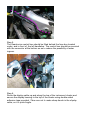
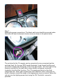
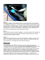
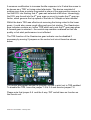
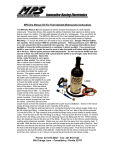
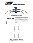
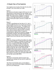
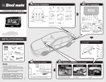
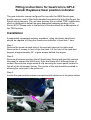
Fitting instructions for Geartronics GPI-4
Suzuki Hayabusa Gear position indicator
The gear indicator comes configured for use with the OEM Suzuki gear
position sensor, and is fitted with standard connectors to plug directly into the
Suzuki wiring harness. The unit also features the so-called ‘TRE’ modification,
which is designed to defeat the gear dependent mapping strategy of the
Suzuki ECU. Please refer to the bottom of this document for a description of
the TRE function.
Installation
A reasonably competent amateur mechanic, using only basic hand tools,
should be capable of fitting the Geartronics indicator in less than 1 hour.
Step 1.
Remove the screw at each side of the seat and remove the riders seat.
Remove the 2 screws in front of the fuel tank. Lift the front of the tank and
support at approximately 45° to gain access behind the engine.
Step 2.
Remove all screws securing the left hand lower fairing and carefully remove
the panel to expose the bike frame. Note that there are 2 different sizes of
screws! Remove the single screw & clip securing the insert panel located to
the left of the instrument cluster. The centre of the clip should be pushed in,
allowing the outer part to be pulled out.
Step 3.
Locate the gear position sensor connectors with reference to the photo below.
Close up of gear position sensor connector
The connectors are 3 pin white triangular, and have pink blue & black wires.
Separate the 2 connectors by inserting a small screwdriver into the releasing
latch and pulling the housings apart. DO NOT pull on the wires to separate the
connectors as damage may result.
Step 4.
Plug the connectors on the Geartronics loom into the two connectors you
separated in step 3. Run the Geartronics loom alongside the existing loom on
the left hand side frame. Secure with the cable ties supplied in the kit.
Step 5.
The Geartronics control box should be fitted behind the fuse box located
under, and in front of, the left handlebar. The control box should be mounted
with the connector at the bottom so as to reduce the possibility of water
ingress.
Step 6.
Route the display cable up and along the top of the instrument cluster and
secure the display housing to the top of the cluster using double-sided
adhesive tape provided. Take care not to make sharp bends in the display
cable, as it is quite fragile.
Step 7.
Making the power connections: The black earth wire should be secured under
the lower left hand instrument cluster screw as shown in the photo below.
The red wire for the 12v supply can be connected to any convenient ignition
switched feed. On the year 2000 model illustrated, it was found that the most
convenient supply was that going to the front light cluster. The front light wiring
harness connects to the main loom using a black rectangular connector
located to the left of the fuse box. The 12v supply was found on the thick
orange/red wire. Other year models may use a different colour code and if in
doubt, reference should be made to the appropriate service manual. Splice the
red wire into the lighting power feed using the 3M ‘Scotchlok’ connector
provided.
Step 8.
Testing the display: check that the bike is in neutral and turn on the ignition.
The display should read ‘N’. The function of the standard neutral lamp should
be unaffected. If possible select 1st and 2nd gears and confirm that the display
reads correctly. It will be unlikely that the other gears can be selected unless
the engine is running, but if the display is reading correctly in Neutral and 1st
then it is fair to assume that all is functioning correctly.
Step 9.
Ensure that no wires have been trapped or incorrectly routed, then replace the
insert panel, the fairing and the seat. Remember that the fairing is secured
using two different types of screw!
Step 10.
Finally, road test the bike to ensure that the display is reading correctly in all
gears. The display should be easily visible, both from under the screen with
you head down, or through the screen with you head up.
TRE function
The standard Suzuki GSX-R motorcycle uses an engine management
controller that sets the various engine parameters depending upon which gear
is selected. Such is the responsiveness of the GSXR1000 & Hayabusa
engines that it was deemed necessary, both as a safety feature and to make
the bikes easier to ride in daily use, to ‘sanitise’ the power delivery of the
engine. Effectively, what was done was to soften the throttle response in the
lower gears by reducing the amount of ignition advance. This softening effect
can be noticeable in the first 4 gears and anything up to ½ throttle. It’s
important to note that there is no reduction in maximum power at full throttle.
A common modification to increase throttle response is to fit what has come to
be known as a ‘TRE’ or timing retard eliminator. This device consisted of
nothing more than a resistor connected in place of the gear position sensor to
fool the ECU into thinking that 5th gear was selected at all times. Interestingly,
the ECU was forced into the 5th gear map so as not to invoke the 6th gear rev
limiter, which governs the top speed of the bike to 186mph on later models!
Whilst the basic TRE was effective at removing the timing retard in the lower
gears, it could also cause rough idling and poor hot starting. The Geartronics
gear indicator contains an ‘active’ TRE which only sets the 5th gear map when
a forward gear is selected – the neutral map remains unaltered so that idle
quality or hot-start performance is not effected.
The TRE function of the Geartronics gear indicator can be disabled if
necessary by moving 2 jumpers on the control unit circuit board as shown
below.
The above photograph shows the jumpers (circled in pink) set to TRE enabled.
To disable the TRE, move the jumper 1-2 to 3-4 and remove jumper 7-8.
Please note that jumper 5-6 and the 4 way ‘DIP’ switch have no function on
the Suzuki unit.
Geartronics / Neil Wallace - February 2005.