1
Repair-works on 2-st,roke engine
fot engines up to 100 cc
www.oudebromfiets.nl
Servicing Manual
for Two-Stroke Engines
up to 100 cc
•
Issued Februory, 1966
,
www.oudebromfiets.nl
Subiekt to alteration.
ZONDA~~·WfRKf
GMBH MONCHfN
8 Munch.n 8, Anz;ngcr StroBe 1-3
~rint.d
in Gerrnony
www.oudebromfiets.nl
FOREWORD
Advances in the design of motorised two-wheelers during the last
few years, particularly for the lower cubic capacities, have
greatly stepped up engine output as well as riding comfort.
lUNDA?P machines, in particular, have led the way and gained
an enviable reputation for good engineering design and solid
construction.
Each new lUNDA?? model will always make its contribution towards jl,lstifying Ol,lr excellent reputation, so as to maintain and
increase the popularity of lUNDA?? machines. One of the most
important factors in ensuring our continuing success is 0 first
class after-soles service. That is why we are anxious to acquaint
all our distributors and appointed service stations with the latest
developments. Throughout the winter months, our lUNDA??
training centres ore holding courses for service mechanics. This
manual is designed to save students at these courses the timewasting trouble of taking copious notes and to be a permanent
record which they can consult at any time to refresh their memory.
The descriptions of dismantling and assembly operations have
been compiled with clarity and simplicity in view and are accompanied by numerous illustrations. We trust that every distributor
who has not yet hod the opportunity to attend a training course
will find the manual a useful aid and reference book.
Reprod~dion. in whole or
In
porls, prohibited, except by prior o~thorj$otion.
3
www.oudebromfiets.nl
•
Table of Contents
r
Page
Introductory Notes
..
7
T. Dismontling Engine
0) Taking off Gear Change Pedal and Fan Casing
b) Taking off Casing (over, left, and Kickstorter
Assembly
8
9
c) Dismantling Ignition System . . . . . . . . .
d} Taking off Clutch Cover, Cover for Clutch and Gear
Chonge,Setting Controls. . . . . . . . . . . . .
e) Taking qff Pedal Gear Chonge Spindle and Selector
Slide
f) Dismantling Clutch . . . . . .
g) Taking off Chain Sprocket. . .
9
10
11
11
12
h) Taking off Cylinder and Piston.
12
i) Taking off Cronk Casing. . . .
k) Taking off Bearings, Bushes ond Clutch Gear.
I} Taking off Steel Ball Selector, on engines with
13
15
manual gear change. . . . . . . . . . . .
16
2. Engine Assembly
oj Setting Steel Boll Selector, on engines with manual
gear change . . . . . . . . . . .
b) Measuring Axial Play of Crankshaft . . .
c] Fitting Crankshaft into Right Casing . .
d) Measuring Axial Play of Selector Shaft.
e) Measuring Selector Gears
f) Measuring Starter Spindle
.
g) Assembling Engine Block
.
h) Fitting Selector Shaft to Bearing on Left Casing
i) Mounting Sealing Rings
.
k} Inspecting Connecting Rod
.
I) Assembling Piston ond Cylinder
m) Mounting Chain Sprocket . . .
n) Measuring Main Drive Shaft Position
0) Mounting Clutch
.
p) Setting Clute, Tongue and (lvtch .
5
www.oudebromfiets.nl
18
18
19
20
21
22
23
25
25
2'
2'
27
27
28
30
q)
r)
s)
t)
u)
v}
w)
x)
Taking off and Mounting Gear Change Spindle.
Mounting Clutch Bell Cover . . . . . . . . .
Setting Pedal Gear Change Spindle. . . . . .
Mounting Cover aver Clutd! and Gear Selector
Anembly (Connector Cop)
Mounting Ignition System . . . . . . . . . .
Setting Ignition Timing. . . . . . . . . . . .
Taking off and Mounting Kichtorter Spring and
Sleeve
Mounting Fan, Left Casing Cover with Kichtarter
and Fan Casing. .
30
33
34
34
34
35
35
36
3. Special Service Tools.
38
4. Bing Carbu","ors
41
. .
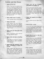
5. Troubles and their Causes.
48
6. Technical Data. . . . . .
49
.
",
6
www.oudebromfiets.nl
Introductory Notes
The comprehensive text of this eXfensively illustrated manual on engine dismantling
and assembly applies with appropriate modifications to all models with manual or
pedal gear change ond kickslorter. Where the assembly sequence differs in {] few
respects, or where different tools are needed, special reference is mode to the
changes in the relevant chapters. The manual covers the following engine models:
Type
Model Description
Starting System Gear Change
System
267
267
267
276
276
276
281
Scooter R 50
Super-Combinelte
Kid<slorter
Manual
Manual
Pedol
Manual
KS 50 Super
Kickstorter
Kickstorter
Kickstarter
Kicksforter
Scooter RS 50
Motorcycle KS 100
Kickstorter
Kickstorter
Pedal
Pedal
Sport-Combinette
Scooter RS 50
Pedal
No. of Gears
3
3
3
••
••
The instructions take account of all modifications introduced on engines supplied as
from 1965.
Complete dismantling of an engine is only called for in cases of damage to the gearbox, cronk drive, kickstorter assembly (except for kickslorter spring) or the manual
gear-change assembly.
Defects of the gear seledor mechanism - steel-ball selector mechanism for pedalchange engines - dutch, crankshaft drive gear of engines with either manual or
pedal gear change, can be remedied after taking off the dutch housing cover. Consequently, the engine need not be token off the frame. But in all these cases, the
gearbox oil must be drained off through the drain plug in the bottom of the housing.
This is preferably done while the engine is still worm.
Gear-d1ange pedal, kickstarler pedal with return spring, chain sprocket, flywheel
magneto (wheel and baseplate), cylinder with piston, cylinder head and fan assembly
can 0/1 be token off and fitted without dismantling the engine. Here, of course, the
oil need not be drained from the gearbox.
for air-cooled engines, consult the assembly instructions on model KS 100, and disregard all references fa the fan system.
7
www.oudebromfiets.nl
1. Dismanting Engines
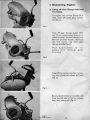
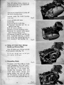
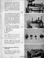
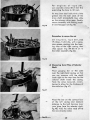
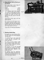
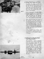
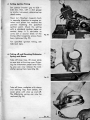
a) Taking aff Gear Change Pedal and
Fan Casing Fit engine into service fixture SK-A
1926, draw off spork plug connector (fig. 11.
fig. 1
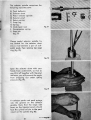
Toke off gear change pedal. With
the 1-4 mm open.ended spanner or
sode.el spanner, slacken hexagon nul.
Remove serrated washer; draw pedal and spacer ring from gear
change spindle (fig. 2).
Not applicable to engines with manual gear
change
fig. 2
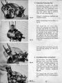
Toke off fan casing cop, first removing two cylindrical screws, M 5 x 15
(fig. 3).
fig. 3
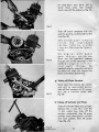
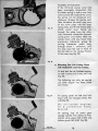
Remove 3 cylindrical screws, M 6 x 45,
from the left side of the fon casing,
then toke casing off (fig. -4).
fig. 4
www.oudebromfiets.nl
8
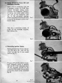
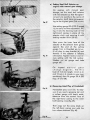
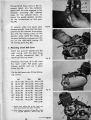
ill Taking oH Casing Cov.r, I.ft, and
lOcks...., An.mbly
With 0 \.0 mm socket key, toke off
2 hexagon screws, M 6 x 35, then
remove feft-hand cosing cover,
complete with kiootorfer, kidtstart·
er spring and cover plato which
0150 octs as the kiootorfer stop
(fig. 5). On air-cooled engines,
slacken 2 cylindrical sCrews, M 6x 45,
instead of the hexagon screws men·
tioned above.
fiil. J
Take the 4 cylindrical screws, M
5 x 20, off the flywheel magneto,
then remove fon.
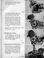
c) DiUftGlltling Ignmon System
Holding the flywheel firmly with ser·
vice tool SK-A 251, toke off the
wheel nut with the 14 mm sodet
spanner (fig.
n.
fig. 1
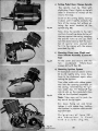
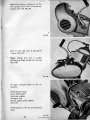
Fit press·off bolt SK·A 263 to wheel,
hold onembly firmly in position
with tool SK-A 251 ond pren wheel
off the magneto spindle on the
cronkshaft. Remember the key which
secures the wheel to the crankshaft
(fig. 8).
9
fig .•
www.oudebromfiets.nl
•
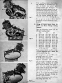
If the work described in the following passoges is confined 10 a repair of dutch and pedal gear
change SySI/Lffi,
a--
the baseplate
can
remain on the left casing. If the engine musl be completely dismantled,
toke the plote off now, firsl removing the 2 cylindrical screws,M 4 x 15,
and the casing screws, M 6 x 92,
complete with coble clip (fig. 9).
1';,_ ,
On engine model 281, the
baseplate is fixed with three screws,
M.4 x 15.
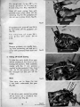
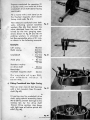
d) Toking 0" Clutdt Cover, Cover for
Clutch and G.Of Change S_"ing
Controls.
Fig_ 10
Take the following screws off the
left-hand casing cover,
.267
276
281
oj M6x92" M6x92" M6x92'
b) M6x98 M6x98 M6x98
c} M6x98 M6x120 M6x120
d) M6x120 M6xl20 M6xl20
e) M6xl20 M6x120 M6x120
f)
M6xl20 M6Kl20 M6x120
g) M6x98 M6x98 M6x9B
hJ
M6x98
M6x98
M6x98
M6lt98
M6lt98
(fig. 9)
Three screws remain on the casing,
2 at the magneto and 1 below the
starter spindle (fig. lO).
On engines, type 281, additionally toke off 1 screw,
M 6 lt 98, obove screw (il.
Remove connector cover closing
off the clutch ro-setting ond gear
change setting controls for pedal
gear change engines. The cover is
filted with two countersunk fillisterhead screws, M 5 lt 15, to the righthand casing covor (fig. 11).
On engines with manual
g e o.r c han g e, the setting dome
for 'odjusting the gear chonge os·
sembly is not provided.
Slacken 2 fixing screws, M 6 lt 12, on
the setting dome (fig. 12).
i)
OJ with cabl, clip
fig_ II
Fig. 12
www.oudebromfiets.nl
M6x98
10
•
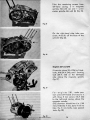
Toke off setting dome, remove cylindrical screw, M61( 45, underneath
starter spindle (fig. 13).
Operate the clutch lever to press off
the clutch housing cover.
localed inside the clutch housing
cover are:
Crutch spindle with lever
Clutch dog
2 reof springs for clutch dog
Ball-headed threaded pin for resf!ting clutch dog .
Bush for starter spindle
Gearbo)( oil level checking screw
Guide pin for selector slide (pedal
gear change engines only)
On engines of type 276 and 2B1, the
third crankshaft belJring is needle
bush 277-01.135; engine 267 has no
third crankshaft bearing (fig. 14).
Fig. 13
Fig. 14
el Taking off P.dal Gftlr Change
Spind~ OIId Selector Slide
Take off pedal gear change spindle
., and selector slide (fig. 15).
Only on engines with pedal gear change
•
f) Dismantling CJutdt
fit service tool SK-A 235" to clutch
with 2 studbolts, SK-A 237, and 1
stud, SK-A 265. Toke off 5 or 10 nuts,
M 4, with the 7 mm socket key.
Slacken the clamping bolt, and
clutch thrust plote; sprinJls and
spring bushes can now be tok"en
off. On engines of type 267, fit the
clomp with 3 5tuds,SK-A.237 (fig. 16).
11
..
~;
Fig. "
www.oudebromfiets.nl
:
Fit hold-down tool SK-A 279 to
dutch thrust plate, then release
dutch nut with the sodtetke (fig.l7).
Fig. 17
Toke af'rdutm complete with hub
and the pocking woshen behind the
hub (fig. 18).
The clutch gear remaIns
inside
the
right-hand
casing, held by a snap
ring on the inside (gearb a x l.
fig.
On engines with pedal
gear change, you can now
drew out the steel·boll selector
through one of the openings in the
dutch. On engines with fIlOnual gear change, ·the
steelboll selector assembly can"only
be token off after the engine has
been completely dismantled.
1.
g) Taking oR Choin Sprocket
Bend open the locking tab washer
and with an open.ended spanner
take off the hexagon nut (if necessary, use a two-orm puller tool,
fig. 19).
fig. It
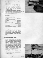
h) Taking off Cylinder and Pitton
Take off cylinder head and cylinder.
Remove the .4 nuts, M 7, with the
11 mm socket key, toke off the
washers underneath, then lift away
cylinder head, head gasket, cylinder
and ~se gasket; take off pisfon
rings (fig. 20).
fig. 20
www.oudebromfiets.nl
12
On engines, type 281, no
head gasket is fitted as
from engine No. 4600937.
•
Press off cronk casing, then with
pointed-nosed pliers draw off tne
retaining ring for the gudgeon pin
(do not use a screw driver, fig. 21).
Fig. 21
•
Fit gudgeon-pin press-off tool SK·A
64 and press off the gudgeon pin
(Ag. 22).
'0'
""
2 68.
engines of type 281,
press-off 1001 SK·A
•
Note
Remove gudgeon pin needle bearing from connecting rod cnd put it
oway welt protected from dust and
dirt.
Fig_ 22
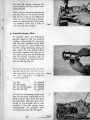
ij Toking off Crank CClsing
To lake the moin duldl drive gear
off t~e cronk.shoft, first bend up the
loding lob washers. Hold assembly
steady with the 11 mm sponner
applied to the Cl"onkshoft flols, then
with the 19 mm sponner toke off
the hexogon nut and pull off the
wheel.
Note
Fig. :u
Toke core not to loose the two
5 mm bolls underneath the gear
(fig. 23}.
If the drive gear cannat be pulled
aff by hand, use a standard two·
orm puller tool (fig. 24).
•
13
www.oudebromfiets.nl
Take the remaining screws from
left-hand casing, 2 in magneto
section, M 6 x 35 (0) and 1 under
starter spindle, M 6 x 65 (b) (fig. 25).
fig. 2.5
On the right-hand side, toke one
screw, M 6 x SO, off the bose of the
cylinder (fig. 26).
Fi,.2'
Engines 2117 gnd ZIt.
Fit service clamp SK·A234 by 2siudboil's, M8 (SK-A 246), and 1 locating
bolt (SK-A 123) on the left·hgnd
side above the mognelo spindle
(fig- 27).
Fig. 21
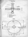
For eng ines 281, make your
own press-off fixture and secure it
with three 8 mm screws SK-A 246
to the left-hand casing above the
magneto spindle.
{The.diometer should be 6 in. (150
mm), \hickness 7 mm, bare 9 mm to
toke the 8 mm bolts, (see special
tools, fig. 28.)
Fi,.21
www.oudebromfiets.nl
14
Take the gearbox block from its
mounting frame and place it, righthand side facing down, on two
wooden blocks. Turn the press-ofi
bolt and at the some time press on
selector and starter shafts to prize
the two gearbox halves apart. Then
carefully lift off the tap half {left}
(fig. 29).
Before taking out the various shafts,
note the position and number of
washers and spacer rings fitled, as
well as the corred meshing position
of geers (and mark these wilh a
reference line for preference).
Careful atlention to correct fit be,
fore starting to dismantle may save
you considerable gauging and seft·
ing work when the engine is reassembled.
Take oul shafts in this sequence:
1. Geer selector shaft with selector
gears and steel· boll assembly
2. Starter shaft
3. Main drive shaft
4. Crankshaft
(fig:3O).
fill. 30
For engines with manual
gear selection, the steetbolt selector remains in
th e selector fork on the
right-hand casing.
Carefully inspect all shafts and
gears for traces of wear and proper alignment as soon as you have
taken them off {fig. 31).
Fill' 31
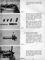
k) Taking oR Bearings, Bushes and
Clutch Gear
On engines of type 2.81,
the 19 rollers, 5 x 3.5 dia., can be
taken oul after removing spacer
ring 281.05.110 (fig. 32).
15
fill.
n
www.oudebromfiets.nl
The clutch gear can only be pressed
off after taking the cirdip in the
casing behind the boll bearing from
in seat with 0 poir of pointed
pliers.
If dutch geor and both boll betlrings are in perfect condition, they
need not be taken off (fig. 33).
fig. U
If necessary, pull the boll betlring
from the dutch goor with a standard bearing puller tool (fig. 34).
Fig. 34
•
Casings should be wormed first for
easy withdrawal of boll bearings
and bushes. Or use the puller tool
to remove them (fig. 35).
-Fit. J5
Q Yoking off Steel Boll Selector on
engin., with monuol 91tC1r change
Bend up the tob of the wosher securing the locknut of setscrew (0).
Sloci~n nut, turn setscrew until
selectqr fork (b) can be swung away
and selecl~r (c) can be token out
(fig. 36).Fig.
:w
www.oudebromfiets.nl
16
2. Engine Assembly
Before assembling the engine, first de<ln all ports thoroughly,
remove the sooling compound from casing rim surfaces and ched:
that all ports and sealing faces are in perfed condition. Replace
defective or damoged parts with Ortginal ZUNDA" Spare Parts.
Gaskets and sealing rings must always be replaced by new ones.
Make sure that all parts, such as spindles, shofts and bearings,
are preSfed home all the way to the stop in their locating bores,
seats, etc. To fit a ball bearing, always heat its housing to opprox. 85 0 C. Coot the sliding and stop faces of all. moving ports
with a generous film of oil. using only the grade and type specified by us. •
.
Cle<ln all metal filings off the magnetic plug in the right-hand
casing.
-
11
www.oudebromfiets.nl
oj Setting St.el Ball Selector on
engines with manual gear change
On engines with manual gear
change, sel-the steel ball selector
with the setscrew so that the spherical port sils exactly in the centre of
the selector shaft bore corresponding to the highesl gear (3rd or 4th).
fie·"
Use seHing gouge SK-A 232 (3-speed
/0) to corry out the adjustment, flft:
ing it into the bearing bush of the
right-hand casing in place of the
selector shaft and securing it with
locking washer SK·A 233 (b).
Now press the inner face of the
selector at the selector lever guide
against the end of the setting
gauge. Turn in threaded pin (c) until all play in stop brocket (d) and
thereby in Ihe selector is reliably
eliminated. Tighten locknut and secure setting with the tab washer.
Slacken nut on gouge and toke
gauge off.
Fla. 31
On 4-speed manual gear
change engines, first fit a
bush of 11.5 mm lenglh, 14 mm o. d.
and 12 mm i. d. (mode in your own
workshop), then fit gauge SK-A 232
(figs. 37 and 38).
b) Measuring Axial Play of Crankshaft
fia. )9
Permissible play is 0.1 mm. To measure it you need a gouging bar and
a caliper gouge with depth scale.
Measure from the contact face of
the right-hand casing to the IIlner
ball bearing rece {fig. 39}.
Then cOfY out the same check on
the le'lt-hand casing and add the
twa values obtained (fig. 40).
Fla. 40
www.oudebromfiets.nl
.IS
Prepare crankshaft for gouging. Fit
a washer with 2 mm bevel on to the
cronkshaft drive shaft (bevel facing
crank web).
Fit a washer with 2 mm bevel on to
the flywheel mogneto shaft (bevel
facing cronk web, fig. 41).
Now measure crankshaft aver both
webs, including special bevelled
washers (fig. 42), then deduct the
value obtained from the sum obtained by the twa gouging operations shown in fig.39 and 40. Fit
packing washers to eliminate all
but the permissible play of 0.1 mm,
0$ shown in the fallowing example.
Fig_ &1
Example:
Left casing
Right cosing
18,4 mm
24,5 ml':l
42,9 mm
Crankshoft
41,7mm
Axial ploy
1,2 mm
0,1 mm
1,1 mm
Standard washer
on drive shaft
Remainder
flywheel magneta shaft
Fill.42
O,5mm
O,6mm
On engin-es of fype 281,
the standard wosher IS
0.2 mm thide.
c) Fitting Cranbhah into Right C05ing
Heat up inner race of boll bearing
with a hot mandrel, then fit crankshaft (fig. 43).
•
Fit sealing ring far crankshaft drive
shaft, using spedal assembly sleeve
MV 6-339 to prevent domage to the
sealing lips by the drive shaft
th~read. Drive sealing ring home
with light tops of hollow punch MV
6-347 (fig. 44).
19
...
.
www.oudebromfiets.nl
For engines of type 281,
use assembly sleeve SK-A 217, firsl
expanding the bore to 13.5 mm.
Fit two 5-mmsteel balls with a little
grease into the boll seats of the
drive shoft (crankshaft) then slide
on the primary drive g8iJr. Finally,
secure assembly with locking washer and hexagon nut (fig. 45).
Fig. U
Remember
to S.CUrtl
the nul
On engines, type 281 ,stick
19 rollers, 5 x 3.5 dia., with a generous grease coating into the bearing race of the right casing, then
slide spacer ring 281-05.110 on to
the roller assembly (fig. 46).
Fig. 46
d) Measuring Axial ptay af Selector
Shah
Place gouging bar or the yoke
over the right-hond casing, so that
you can measure with the depth
scale right to the stop face for the
selector shaft inside the casing.
Nole the value measured, remem·
bering to allow for the thickness of
the scole bar (fig. '4n.
Fig••,
•
Place the bar on the contact face
of the left casing and measure
distance to the boll bearing inner
race (stop face for selector shaft,
fig. 48); Add the value read off to
the one already noted.
Ftg...
www.oudebromfiets.nl
20
NON: Remember to allow for thiclc·
ness of bor.
•,
,
Now measure selector shoft bel·
ween the two stop foces (fig. 49).
This volue will always be smaller
thon rne sum of the two obtained
10 fig. 47 and 48.
Fit washers on the shoft between
boll bearing and speedometer drive
until only a ploy of 0.1 mm remains
(for swinging fork machines).
fill_ 4t
Example:
, .
Measurement obtamed
10 fig. 47
T2;Jmm
Measurement obtained
10 fig_ 48
_+-,--~34;;;,9~m~m~
Sum
57,6 mm
Dimensions, fig. 'Jl
56,9 mm
O,7mm
Axial ploy
Pocking washers required
0,1 mm
O,6mm
For engines of moe hines with
telescopic fork, a spocer
bush is fitted to the collor of the
selector shoft, since the speedomeler drive is laken from the front
hub.
e} Meas",ing Selector Geo",
i
Fit the selector shoft with the number of pocking washers calculated
into the left casing, then At selector
gears in sequence in such a way
thai the lorger collar faces down,
i. e. towards the larger gear. Gears'
ore correctly fitted if only ontt oil
groove lies between each two
gears, and the arrow at the side
points to the next larger gear.
Next, with the depth gouge, measure distance from end face of
selector shaft to stop foce of selector geor (fig. SO).
21 ,
•
fig. 50
www.oudebromfiets.nl
Then' measure from the same point
to Ihe stop collar of selector shaft
(fig. 51).
fit. 51
The distance must not be lorgerlhon
the value obtained to fig. SO. Correcl any boddash in gears by fitting
pocking washers between 1sl and
2nd speed gear; ploy must be eliminated 10 0 (fig. 52).
Note: The bolls for the seleclor
gears should be coated with oil, nol
with grease, 10 stick"them into position. Before fitting selector shaft,
check that stop pins of selector
shaft are correctly mounted, complete with their annular springs.
fig. 52
f) M.cnuring 5tarlw Spindle
Check distance of opposing teeth
between driver and kickstorter gear
on Icidc.storter spindle. This should
not exceed 0.8 mm. If it does, fit
packing washers between shop ring
and driver. A washer of 1 mm is
fitted to the short shaft stub a}
standard (fig. 53).
.
,•
With gouging bar and depth gauge,
measure distance between contact
face
right casing and stop collar
fo"r starter spindle {fig. 54}. Note
down the reading.
of
www.oudebromfiets.nl
22
On the left casing measure the
some distance with the some instru·
ments (fig. 55).
Next, measure distance between the
two stop faces on the starter spindle
(fig. 56), then make up the difference
from the sum of the two measurements just described by fitting pod:ing woshers, until only a ploy of
maximum 0.3 mm remains.
Fig. 55
Bkldl
9) Assembling Engine
,
Fit selector shaft and kidularter
spindle together with the podcing
washers detennined by gauging,
and the main gearbox drive shaft
with a standard 1 mm washer into
the left casing. Set broke spring so
that when the two casing halves
are fitted together, the stop pin in
the right casing can be introduced
into the spring. locating stop on
starter spindle must face bore mark·
ed )( on housing (fig. 57).
The assembly notes on the
locating stop of the starter spindle apply only up
to the engine numbers
listed below,
Typ
Typ
Typ
Typ
267
267 (R 50)
276 (KS 50 Super)
281 (KS 100)
~.
Fig_56
Nr.3525493
Nr.8000639
Nr.4056928
Nr.4601353
•
As from the succeeding engine num·
bers of the types listed and on all
RS 50 models righ' from the start,
the kickstarter stop has been transferred to the outside and is now
located in the left casing cover.
Consequently, Ihe assembly notes
accompanying figs. 93---95 apply.
23
'.
Fig. S1
www.oudebromfiets.nl
,
Press clutch gear (if earlier taken
oft) into right casing, Ihen secure it
from inside with the snap ring (see
fig. 33); Ihe pre-ossembled right
casing is shown in figs. 24 and 26.
Mount two press-fit bushes, coot
casing contoct faces with compound, such as Teroson Almasit, oil
shafts and bearings, Ihen carefully
fit both casings together, taking
core 10 position the broke spring
correctly. It is advisoble 10 lift the
storler spindle up from underneath'
until the slop pin engages with Ihe
broke spring. so Ihol the spring
cannot shift out of position as the
two casing halves ore fitted logether (fig. 58).
Fit!. 5.
/
,
•
Bolt casing halves together on the
left with 2 bolts, M 6 x 35, at the fly.
wheel magneto side (o) and below
the starter spindle (b, fig. 59).
.on the right hand, fit 1 bolt, M6xSO,
-at th~ cylinder base (shown
arr~w
~."
www.oudebromfiets.nl
on fig. 26).
by
h) Fi"ing Selector Shaft to Bearing on
Left Casing
Fit 1 ring (made in your shop) of
the following dimensions:
i
Height
6 mm
Outerdio.
36 mm
Inner dio.
31 mm
on to selector shaft, flud.. against
Ihe casing. Fit chain gear and tighlen gear nul to shift shaft upwards
bringing its collar all the way
against the inner race of the ball
bearing.
fit·"
Taite off nut, chain gear and ring
again (fig. 60).
On engines of type 267,
use spacer ring SK·A 138 for driver
in place of the ring just mentioned.
Hoving fitted the ring, fit and run
down chain gear nut a n Iy.
,
.
Chede that all shafts move smoothly.
i) Mounting Sealing Ring.
Fit engine into service fixture SK·A
126 and clomp the whole ossembly
into the vice.
1
I
Fit seoling ring to left casing; fit
sealing ring for crankshaft with
punch MY 6-961.
Fit sealing ring for seleclor shaft
with ossembly socket sleeve SK-A
217 and drive it home by topping
with punch MY 6-734.
On engines of type 267 (monuat
and pedal gear chonge):use sodeet
sleeve MY 6·960 together with
punch MY 6·961.
Fit, sealing ring for kickstarter
spindle with hollow punch MY 6·734,
noting that chamfered side of ring
must face casing (fig. 61).
2S
fig.
'1
www.oudebromfiets.nl
k) Inspecting Connecting Rod
Fit gauging ring SK-A 125, needle
bearing and gudgeon pin into connecting rod. Turn crankshaft down
until gudgeon pin lies againstgauging ring. Check thai it contacts
flush on both sides (fig. 62).
Gauge in turned-over position and
compare results.
Fi,.62
Adjust connecting rod as shown in
fig. 64.
On engines of type 281,
place two gauging bars SK-A 161
on both sides of the connecting rod
on the casing face accommodating
the cylinder base gasket. Turn the
crankshaft until the piston rod edge
lies against the bars. Then repeat
the gouging in the opposite position.
Adjust the connecting rod as shown
in fig. 63.
Fig. 63
Cony out final conneding rod setting with the setting bar MV6-116
(fig. 64).
I) Assembling Piston and Cylinder
Fit the piston; the mark "Auslass·
(llxhoust port) must face towards
the exhaust. Introduce gudgeon pin
with service tool SK-A 163, fit
crankshaft cover, then fit retaining
rings. Position cylinder base gasket,
but without sealing compound
(fig. 65).
On 'engines of type 281,
use tool SK·A 272 to fit the gudgeon
pin.
F1,.65
www.oudebromfiets.nl
26
Fit piston ring and support piston
with a special fork 1001, mode in
your workshop [Ag. 66).
'~.
Fit cylinder (introduce piston carefully and gently into cylinder to
prevent fracture of pisIon ring).
"
Note: The locating pin in the pislon
ring groove must sit inside the ring
ioint. Fit cylinder head gasket and
cylinder head. Fit -4 packing washers, then tighten the -4 nuts, M 7,
with ll-mm socket wrench, working
always on diagonally opposite nuts
in turn; torque 10.6 Ib-ff. (1.5 mkg.,
see Ag. ~71.
_. .-
'"
C·
Engines of type 267, -276
[without fan) and 281 have
two piston rings.
FI,. 67
~
m) Mounting Chain Sprod:et
Fit the sprodcet and secure with
washer and hexagon nul; use the
chain assembly fool fa hold assembly firmly' in place. Secure nut
with tab woshet" (Ag.68).
•
f',."
nJ Meoluring Main Drive Shoff POlition
Fit the dutch hub, cover plate and
dutch nut. With a wooden spatula
or other 1001, shift the cover plate
to the top position, then with Ihe
depth gouge ins-;'rted through Ihe
marking bore measure distance to
the c1ulch gear - it should be 22.5
mm (fig. 69).
27
fi,. "
www.oudebromfiets.nl
t
-
Toke the tool away from the cover
plole and press main drive shaft
dawn all the way to the stop, then
measure distance ogoin - it should
be 21.8 mm.
Example:
22,5 mm
- 21,8 mm
0,7mm
The values and final c1earonce listed are only given as examples
(fig. 70}.
",. 10
To obtain the required axial play of
0.1 mm, fit 0.6 mm paddng washers
between ball bearing in clutch gear
and clutch shiftor hub (fig. 71).
...
0) Mounting ClutdJ
The clutch shown in fig. 72 is fitted
to the following engines:
Type 267 up to No. 3484 123
Type '06 up to No. 4045 406
Type 281 up to No. 4600 606
,
fOtl. n
Fit retaining, lining and outer steel
plotes, then fit cover plate. To olign
bores for the spring sleeves corred·
Iy, the clutch shifter hub is marked
with a reference line and all ploles
with internal splines have a special
aligning bore. Make sure that all
these bores are accurotely aligned
on the line mark (fig. 72).
Hoving fitted the cover plate, run
down the nul end tighten it firmly,
holding the assembly steady with
tool SK·A 279.
' •• 72
www.oudebromfiets.nl
28
Clutches with 4 plotes (fig.73) are
filled to:
Type 267 as from No. 3484124
Type 276 as from No. 4045407
Type 281 as from No. 4600607
.
All scooter engines are filled with
+-plate clutches. Assemble as follows:
Fit retaining plates, lining and outer
steel plales, then fit cover plate.
Here again, the clutch hub has a
reference line and all plates an
aligning bore.
Fig. 73
Underneath the reference bore on
the cover plate, on arrow is additionally marked which must be in
line with the mark on the hub. Also
note that the dished side of the
upper steel plate must face the
gearbox. -Hoving ploced the fourth
plole in position, fit the cover plate
so that the dished side faces the
gearbox.
Hoving filled the cover plate, run
down the nut, hold the assembly
tightly with tool SK-A 279 and tighten nut firmly (fig. 7.3).
•
I
,
Next, insert the spring sleeves, complete with springs, fit special service tool SK-A 234 (as shown on
fig. 16) and insert thrust plate between clamping bdlt of the tool and
the clutch springs. Press clutch
springs together, and you can then
fit and lighten the 5 or 10 nuts, M 5.
Toke off the service tool, fit thrust
pin with the required pocking
washers to Ihe thrust plate (fig. 74).
Fig. 1f
29
www.oudebromfiets.nl
p) Setting Clutch Tongue and Cluten
To obtoin the largest possible resetting fenge, the clutch tongue must
be set to the mushroom-shaped
thrust pad. To do this, first cool the
pod with chalk, then fit the e1uta.
bell cover and operate the c1utdl
lever on the housing.
fie. 15
Take the bell cover off again, check
whether the thrust pad contacts the
longue roughly 01 the cenlre. If it
does not re-set with the setscrew
for the thrust plote on the bell
cover, then secure the new setting.
Next, dleck the clutch lever ploy at
the housing. In its resl position, it
should be possible to move the lever
by hand about 2-3 mm in its bearing at the clutch tongue. If the ploy
•
is too large or too small, cor"rect by
fitting or removing the appropriate
number of washers under the thrust
pod (fig. 75).
•
The following noles, up
to fig. 85, apply only to
engines with pedal gear
change.
•
q) Taking aff and Maunting Pedal
Gear Change Spindle
\
The assembly is shown in fig. 76.
Inside the powl mount C are the
two gear-dJange pawls D with
spring. Seledor drum B engages
over the pawls; above the drum
sits pawl deflector A with return
spring. The whole assembly is held
by snap ring F. In case of damage
ta the selector spindle, we supply
the complete assembly for replace.
men), but the return spring is available \os a separate repoir part
(fig. 76).
'ig.7'
www.oudebromfiets.nl
30
The selector spindle comprises the
following separate ports,
A) Powl deflector
B) Selector drum
C) Pedol selector spindle
0) Selector pawl
E) Return spring
F) Snap ring
G) Spring
H) Oval·head rivet
I) Compression spring
J} Stop pin
(Ag_ 77)
J
00:
G
•
Fig. 77
Clamp pedal selector spindle by
the thread for the selector drum
into a vice between a pair of soHmetol pods, then remove top snap
ring (fig.7B).
Spon the se'lector drum with your
hands from underneath, so that as
you lift it off together with the pawl
deflector, you will prevent the pawls
from dropping out under spling
pressure (fig. 79).
flg.
n
Fit selector pawls and pawl springs
into the groove on the selector
spindle. Note that the large side
faces on the tapered pawls should
face the cylindrical pin in the pawl
mount on the spindle (fig. BO).
31
'ig. ID
www.oudebromfiets.nl
o
•
I
A
,
Fit the selector drum on to the pedal
selector spindle, pressing the pawls
inwards as you do so. The collar
with lhe recesses oCling as internal
stops must face the cylindrical pin
on the spindle. Tilt the drum 01 a
slight angle 10 make il easier 10 fit
(Ag.81).
FilJ.'1
To fit the return spring to the pawl
deflec:lor, insert it with its top sfop
info the lower recess and with the
bottom slop into the lop recess of
the pawl deflector. The spring
should be unloaded.
It is advisable 10 ease the spring
into position with a pair of flat
pliers to ensure Ihot the stops enter
the r&Cesses for enough. To turn the
spring, use only a screw driver,
pliers or similar tool. To make the
fitting eosier, you con use a second
screw driver to" press the spring
against the recesses in the pawl
deflector as you coil and ease it
into position {fig. 82).
fil.12
Next, fit the pawl deflector, complete with return spring, to the
pedal gear selector spindle. Note
that the cylindrical pin in the powl
mount must be fitted through both
arms of the return spring. To check
correct assembly, fit assembly pin
SK-A 213 into the recess of the powl
deflector, when you should be able
to move the deflector to bath sides
under spring loading (fig. 83).
Fit the snap ring into the groove on
the spindle, then turn the pawl deflector to expose the bare into
whi~ oval-head rivet (H), compress'ion spring (I) ond stop (J) ore fitted.
32
www.oudebromfiets.nl
Hoving fitted these parts in the sequence listed, turn the deflector
again until the stop engages in the
recesses providing the internal
stops for the selector drum. To
mount the pedal selector spindle,
set the transmission to 2nd gear
(,g. ").
Fit selector slide and pedal gear
change spindle. Note that the taper
groove on the seledor dl1Jm engages with the mating piece on the
selector slide, while the recess on
the pawl deflector engages over the
pin on the right-hand casing. Oil
all moving ports (fig. 85).
Fig.1A
r) Mounting Clutch B.II Cover
Insert two press-fit bushes into the
right casing, coat the joint faces
with sealing compound, then fit
clutch bell housing cover.
Fig.
as
Introduce one bolt, M 6 x 45, from
the right under the\. pedal gear
change spindle and I1Jn it down
firmly (fig. 86).
-~
On the left-hand side, fit the following screws,
V,
267
A)
M6xl20
M6x
120
8)
q M6x98
0) M6xl20
E) M6x98
M6x98
F)
0)" M6x92
H) M6x98
I)
M6x98
M6x 120
M 6 x 120
M6x 120
M6x 120
M6x98
M6x98
OM 6 x 92
M6x9B
M6x98
281
M6x 120
M6x 120
M6x 120
M6x 120
M6x98
M6x98
°M6x92
M6x98
M6x98
uM6x98
Fig.1A
-~.
oj Sc.ew wit~ C<lble dip to be litte<! only
ofter bOie pl"te ~ai been mounted
oOJ Only fitted to engines of type 28I L where
it is 10000te<! between I ond G [Iig. 87).
33
"g. 17
www.oudebromfiets.nl
5) Setting Pedal Gear Change Spindle
The spindle must be fitted with
slight ploy. Preu it lightly to the left
(seen in direction of travel) all the
way to the slop.
Screw on the selting dome, running
it down until il lightly contacts the
face of the casing, but without altering the axial location of the
spindle (fig. 88).
Fig."
Now, draw the spindle to the right
and turn the setting dome further all
the way against the cosing, counting
the quarter turns as you go. Then
turn Ihe dome bode by half the number of quarter turns counted and
fix it to the casing with the screws
provided (fig. 89).
t) Mounting Cover over Clutch and
Gear Selector Auembly (Connector
Cap)
Fit the cover and secure with the
two
countersunk
fillister-heod
screws, M 5 x 15 (fig. 90).
"g.•,
u) M04,Inting Ignition S~ .......
Fit baseplale and run down screws
M ..( x 15, lightly only, since these
have- to be slackened again when
setting the ignition.
Fig. to
Then slide coble with rubber gramme' into the opening provided on
the casing, remembering the igni.
tion coble clip. Fit Woodruff key
into ils slot on the crankshaft, then
slide on the flywheel magneto.
Note: Toke core not to push the
key out of its sial again.
Run down fix.ing nut and firmly
tighten it with socket key, holding
.the flywheel in position with service
tool SK·A 251.
,
On'engines of type 281,
lile 'baseplate 15 fixed
with 3 screws (fig. 91).
Fig. '1
www.oudebromfiets.nl
•
'I) Setting Ignition Timing
"'
Set conloct breaker gop to 0.350.45 mm, then, with a dial gouge
or similar instrument, determine top
dead cenlre.
Ned, turn flywheel magneto bock
in opposite direction to engine rotation until pislon has reached the
position matching the specified
ignition point. Check the seHing
with a standard ignition tester or
control lamp. II is advisable to
corry out 0 second check of the
timing after boseplote screws hove
been tightened (fig. 92).
fig. 92
For specified ignition timing, see
technical data.
,
w) Taking off and Mounting Kickstarter
"
Spring and SI88ve
Toke off snop ring, lift cove'r plate
on one side at the stop nose. Gripping the kickstorter pedol lever firmly, you con now release the kick- .
storter spring from load (fig. 93).
fig. tJ
.
Toke off lever, complete with sleeve
one;! sealing ring from below, lilt
cover plole with stop up ond off.
The krclcstarter spring con now be
replaced (fig. 94).
fig. ,.
35
www.oudebromfiets.nl
Assembly of KiOOtarter.
If the left-hand casing caver had
been completely dismantled, first
fit starter spring in such a way that,
seen towards the inside of the cover,
the spring can be tensioned anticlockwise. Grease the spring well.
Then introduce the small stop nose
of the cover plate into the inner
spring loop, ond fit the sleeve, kickstarter pedol lever facing up,
through the plate from the other
side; remember dledr:plote between
casing ,cover and sleeve. Hold the
casing cover with one hand, th~n
pre-tension kickstarter spring by
turning kickstarter pedal lever
through about 1 revolution, until
the stop nose lies iust in front of
the top stop on the cosing. Finolly,
fit the snap ring (fig. 95).
Fig. n
Fig. "
x} Mounting ton, Left Casing Cayer
with Kiclttorter and Fan Casing
Fit and bolt fan to flywheel magneto witJ, 4 cylindrical screws, M 5 x 20
(fig. 96).
•
The following can only be carried
out after engine hos been fitted
into frame:
Fig. t7
Fit casing cover on lelt and bolt
down with two hexagon bolts, M 6
x 35 (fig. 97).
On oir-cooled engines,
fit 2 cylindrical bolts,
M 6 x 45.
Fit sealing ring of pedal gear
dlange spindle into sleeve of kickstarter: using sleeve MV6-1563 and
hollow pundl MV 6-347 (fig. 98).
Fig. ,.
www.oudebromfiets.nl
36
Mount fan casing, bolting ilia the
left cosing cover with 3 cylindricol
screws, M 6 x 45 (fig, 99),
I
,
fig. "
Bolt on fo'n cop with 2 cylindrical
scr.ews, M5x·14.
Note: Check that the 2 rubber
buffers are fitted inside the fan cop
(fig. 100).
fit. 100
,
Fit geor chonge pedol
quence:
111
this se-
Bult\ (spacer ring)
lever with pedal
Serroted wosher
Hexagon nut
Plostic p'edal cover sleeve
(fig,lOl),
Refill gearbox with oil, see technical
doto.
www.oudebromfiets.nl
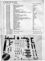
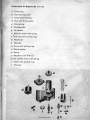
3. Special Service Tools
lJIustr. Order No.
0
b
,
d
•f
~,
k
I
m
0"
p
,q
,
t
•"w
•y
,
01
b1
"
dl
.1
SK-A 126
SK-A 251
SK-A 263
SK-A 234
SK-A 237
SK-A 265
SK-A 279
SK-A64
SK-A 268
SK-A 2-46
SK-A213
SK-A 232
SK-A 233
SK-A 161
SK-A 206
SK-A.217
SK-A 138
SK-A 125
SK-A 163
SK-A 275
MV-6-339
MV-6-347
MV-6-961
MV-6-734
MV-6-960
MV-6-115
MV-6-1563
to be mode in
own workshop
to be mode in
own workshop
to be mode in
own workshop
Description
For use, see fig. No.
Engine clamping fixture
1-28,61-96
Flywheel magneto key
_7,8,91
Press-off bolt
8
Clomp
16,27,74
Studs
16,74
Clamping stud, 8'" long
16,74
17.73
Assem~ key
Press-o too for gudgeon pin
22
Press-off 1001 for gudgeon pin, 75 and lOOcc 22
Stud
27,28,29
Supporting pin
27,29,83
Setting sleeve, 3-speed engines
37,38
Clamping snap ring
37,38
Gouging bor
39,40,63
39,-40,63
Gouginr, yoke, i, reloce of SK-A 161
.'.ssemb y sod:et s eeve for seledor shaft
«,61
Spacer nng for driver
60
62
RingJr0uge
Man rei
65
Mandrel, 100 cc
65
Assembly sleeve
44
Hollow punch
34,98
Hollow punch
61
Hollow punch
61
61
Mounting sleeve
Aligning bar
64
Sleeve
98
28, sketch on p.39
Press-off plate
Ring for selector shah
60, sketch on p. 40
Spacer sleeve
37,38, sketch on p.40
5
•
a1
www.oudebromfiets.nl
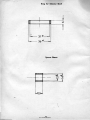
-
Press-oH Plate
o
,
0
b
,
d
,
~
~
-
Thrust bolt
Hexagon nut (welded an)
Steel grade 37 K
Cylindrical pin
Pressure pad
•
atQ.1
•"
M
."
t.
•
-
_.
o'
d
"N
"
39
www.oudebromfiets.nl
Ring for Selecto, Shaft
,
1--- 31'"--1
36 "''-----i
Spacer SI...e
- N
....
•
,
www.oudebromfiets.nl
4. liNG Carburettors
Operafion
The coroorellor is designed to supply the engine with the correctly proportioned and
thoroughly mixed fuelloir mixture to match any lood.
The mixture is prepared in one idling and one main jet system. The idling jet system
supplies the engine at the lower speed stages. II consisls of the idling fuel iet, the
idling air jet and the air odiuster screw. If the air inlet is partially throttled with Ihe
adjuster screw, the idling mixture becomes richer, if more air is admitted the mixture
becomes 18<lner. CarbureHors on small engines have no separate idling iet system;
instead the needle jet system provides Ihe mixhJres at all stages.
•
As engine speed increases, iJ;le main iet system carnes into action, consisting of main
jet, mixing chamber insert or fixed atomiser and needle iet. The exchangeable main
iet sils in the nozzle blod:, screwed from below - or from the side on inclined-jet
carburettor designs - into the carburettor housing. On carburettors with fixed
atomisers, the main iet is screwed to the lower end af the needle iet. As the main
iet system comes into action, the fuel flows via the main iet to the needle jet. The
outlet bore of the needle iet is located in the mixing chamber where the preliminary
mixing of fuel and air takes place. Here, little fuel, air bubbles form which are then
mixed with the main air flow stream and drown into the engine combustion chamber.
A tapered needle, fixed to the Ihrottle slide, controls the available needle jet cross
section. Operation of Ihe throHle slide drives the needle further into the iet, thus
narrowing the free cross section between needle jet bore and needle, or, vice versa,
draws the needle further out and thus increases the cross section.
The needle shonk has severol grooves, so that the needle can be re-sel in relalion
to the throttle slide. If the setting is altered so as 10 drive the needle deeper into
the bore, Ihe engine is supplied with a leoner mixture. If the needle is set higher on
the IhroHle slide, the available flow cross section increases and, consequently, the
mixture becomes richer. The needle setting will only inftuence fuel consumption under throttle control. With Ihe throttle fully open, fuel consumption is exclusively
governed by the main jel.
"tting CGrb",ettOf.
Corburettors must be mounted with special core. They must be positioned accurately
vertical and fitted flush and precisely on their connecting socket. The slots of the
clampi!l.8 connecting fitting must on no accaunl admit secondary intake air, otherwise a steady, quiet idling speed cannol be set. Where connecting flanges are provided, use only gaskets in perfect condilion and tighten nuts evenly. Fix Bowden cable
sleeves without any sh!;!rp bend or kinks. Check that throttle slide opens and C:OS8S
all Ihe way as you operate either lever or twisl grip. On carbureltors wilh starter
jets, the Bowden cable hooked 10 the storler piston sHould heve a little play to
ensure Ihal Ihe piston provides 0 reliable seal.
41
www.oudebromfiets.nl
Ccubu,.tto, Mainlenance
From time 10 time, the carburettor should be rinsed out with petrol and thoroughly
cleaned. While this is done, check that all ports.are in perfect-condition. Replace
worn float needles, needle jets and jet needles, as well as throttle slides, since these
govern engine performance and fuel consumption. On carburettors with separate
starter iet assembly, test that starter piston has tight seal. The air filter should also
be rinsed at regular intervals in either kerosene or petrol. After cleaning, coot the
filter mesh with oil.
Where a screwed hose union is fitted, toke this off, draw out the filter element and
clean it, slacken the connector nut and toke off floot cop. On carbureltors with side·
mounted float housing, slaken the two screws on the cover, toke off the cover, then
toke float
, from housing. The float should drop by its own weight from its suspension
on to the bottom of the float cop, so that it can readily be lifted out. The float
needl~ can then be removed after taking off the spring-loaded retaining clip. On
some versions, the float lies loosely in the cop. The forked port which prevents the
float needle from dropping out can be token off after its fixing pin has been drown
off. Do not bend the fork piece and check that it lies horizontally in its top position.
Never use a sharp, hard tool to c1eon the needle seat or the jet bores, but merely
rinse them out carefully, then blow them out to remove all liquid. Do not tighten the
locknut too hard, but run it down by hand only. Use only the original sealing rings for
the float cop seal. Toke core not to bend the float sealing edge, otherwise the flool
may become displaced up or down and no longer seol off the float needle. This
would lead either to fuel leaks or to a portial or total fuel blodcoge.
Use only absolutely clean fuel and fill it through a filter into the tonk to prevent
trouble with Ihe feed system. Before fitting the fuel hose, first allow a little fuel to
run through it to drive out all the air and prevent the formation of bubbles and on
airlock in the system.
Special Hints
I. The carburetlor is one of the most delicate ports of the engine. Handle all ports
with great core, run down aU threoded connections lightly, never use force to
fit any ports of the f100t into position.
2. Do nol use hard, sharp tools to clean the iets. On no o«ounl, enlarge nonle
bortl$ with a reo",er or by ony ather means.
3. Fit only Original BING spare ports to ensure troublefree operation and a long
service life.
4. Irl""bll your spore port orders, quote port No. accurately and in full. If the num·
ber is not known, quote the corbureltor type code, stomped into the casing, or
send old port as a sample.
-
5. BING carburetlo~s will give excellent service at all times, provided standard goodquality bronded fuels are used, carburettors ore k'epl c1eon and only Original
BING spare ports are filled.
.2
www.oudebromfiets.nl
Carbu,etlo, Setting
Manufacturers of corburettors work out the most suitable design and select the jet
sizes in dose collaboration with the engine makers. They also specify the setting
which tests have shown to give best performance and maximum economy. It is, therefore, inadvisable to deport from their specifications
Idling
Idling speed should always be set or regulated while the engine is warm. With
the adjuster screw, close the throttle slide until the engine just tids over slowly and
steadily. On corburettors without separate idling speed system, the needle jet assembly supplies the amount of fuel required for idling speed. Carburettors with
separate idling speed system work as follows:
,
The air adjuster screw controls the ratio of the fuel/air mixture supplied by the idling
speed system. By turning the odiuster clockwise, the mixture becomes richer, by
turning anti-clockwise, it becomes leaner. The selling is correct when the engine ticks
over quietly and evenly. As soon as it does, do not alter the air adjuster setting again,
since this also governs the lower and medium speed range, so that any further adjustment might increase fuel consumption.
When the throttle is slowly opened out, the engine should steadily rev up. It should
neither splutter nor should the speed drop back again at any throttle setting. If the
engine splutters or speed rises in surges, or if black romes escape from the exhaust
silencer, the ~ixture has been made too rich. If lhe engine coughs or cuts out for
brief moments, if a blue flame blows bock from the carburettor, or if the engine is
difficult to start, the mixture has been set too leon.
Driving SP"d Ronge
In order to determine the most suitable main jet for a corbureltor, first toke the
machine on a straight, level rood and find out its maximum speed by the speedometer
or with a stop watch. Generally, the main jet which will produce the highest speed on
a level rood will be the most suitable for any machine. But 1'f on long continuous
runs 01 full throttle the engine storts knocking due to overheating, seled the nexl
larger jet size.
rn the medium speed range, corry out fine settings between two needle jet sizes by
means of the needle. By setting th~ needle higher, the mixture will become richer and
vIce verso.
Note that needle position only affects the mixture ratio in the lower and medium
speed ranges, not for driving at full throttle. If the corburetlor is correctly set, the
ins11'1otor of the spark plug will show on even brown combustion coating. A spork
plug coated .with black coking residues or wet to the touch is a sure sign that the
mixture is too rich, a white insulator shows that it is to·o leon.
Always remember that only correct carburettor selting guarantees maximum running
eCOnOmy.
www.oudebromfiets.nl
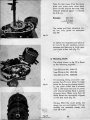
Starter Systems
To start a cold engine needs a specially enriched fuel mixture. To supply this, many
carbureHors have a separate starting system.
Start.r Air Shutter (see c;orburellor for R 50 and 11:$ SO)
On some c;orbureHor types, the starting aid consists of a pivoted shutler in the filter
chamber, operated by Bowden cable. When fhe starter knob is pulled, the shutter
substantially narrows the carburellor crass section, 50 that the mixture will become
rich enough to start a cold engine.
Stan.r Air Slid. (see carbureHofS for KS 50 Super, Sport-Combinelte and Super-Combinelte 433)
•
With these designs, the engine is storted from cold as follows, Close throttle slide
all the way, and with the pressure pin and knob, press the starter slide down. As you
start, pull out throttle about one·third to one-half of the way to a dearly perceptible
stop. Once the engine has come to life, leave the throttle in this intermediate position,
until the engine has run itself worm. Then open throttle all the woy, ond this will also
roise the storter slide to its end position where it engages. If on starting you inadvertently pull out the throttle too for so that it overrides the stop and tokes the starter
slide with it, so that the knob jumps back again, press the starter knob once more.
Startor-Jet CttrbureHors (see corburettar for KS 100)
-
On these designs, 0 cylindrical sforler-iet housing is arronged next to the main twusing, whose piston is operoted by Bowden coble. In its top position, the piston uncoven lhe port which admits starting oir from the filter socket and the storting fuel
mixture port leading to the carburettor intake socket. Fuel enters from below lhrough
the storter jet into this housing, which generally also hos a storage chamber.
When the engine is started from cold, the piston is raised, while the throttle slide
remains dosed. The fuel is fint drown from the storage chamber ond when this is
emply, through the starter jet. It is then mixed with the starting intake air to produce
at first a very ridl mixture which becomes groduolly leaner 05 it flows directly into
Ihe intake socket of the corbureltor and from there to the engine. Once the engine has
run itself worm, shut off the starter piston.
,
www.oudebromfiets.nl
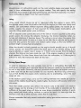
Carburettor for Engines 267, 276 (R SO, RS 50)
a) Carbureltor housing
b) Cover plote
cl Hose union with sealing ring
d) Adjuster screw with spring
e) Collared screw with spring
f) Starter shutter
g) Float
h) 'It:loal cap
i)
Pin
k) Floot needle
I} Sflde spring
m) Throttle slide
n) Needle jet
0) Main jet
p} Washer . '"
q) Jet needle with locating plate
cj
+e
Itf
,
Ok
m
qT 0 aI
p
In
I
Ii
9
h
www.oudebromfiets.nl
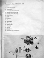
CClrbur.nClI'I for Engines 267, 27'
(KS 50 Super, Sporl-Combinetle and Super·Combinette 433)
oj Carburellor housing
bJ Slorter slide
c) Cover plate
d) Throttle slide
e) Slide spring
f) WosheI
g) Jekneedle with locating plale
h) End plug with sealing ring
i) Needle jet
k) Main jet
I) Adjuster screw with spring
m) Float with float needle
n) float
~ou5ing
cover
c
n
~.;.':::::<
~~,::-
-.. .... .',....,.
,
www.oudebromfiets.nl
~-,
-,
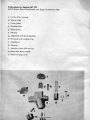
Carbure"ors for Engines 281 (KS 1(0)
oj Cover plug
b) Float housing cover
cl Corburet/or housing
d) float with float needle
e) Slide spring
f) Throttle slide
g) Jel needle
h) J(djusler $cre~ with spring
i) ·End plug with sealing ring
k) Needle ie'
l) Main jet
mJ Screw with seoling ring
nJ Starter piston
0) Spring
pI Adjuster screw with nul
q) Air control screw with spring
rJ Screw with seoling ring
5J
Idling
ie'
b
e
d
f
-{
~
•
I
'k
-I
www.oudebromfiets.nl
Ip
9
1
"It
r
5 '
JO .q
lin
Troubles, and their Causes
1. Engine will not start
7. Engine starts, bUI runs irregularly
and splu"e,. on throHling up
Couse: Fuel lop not opened, slorter aid not operated when starling
from cold. Jets dogged. Corburellor
flooded (engine drowned). Ignition
not switched on. Sporle: plug defective, spark too weak. Spark (electrode) gop on plug too lorge, spark
plug short-circuited, gop clogged by
dirt waler or oil.
•
Couse: Mixture 100 "rich (fit smaller
jets, alter needle selting of throttle
slide). Air filter dirty. Float overflows. Ignition cuts out. Spark plug
oily or coked up. Storler piston not
completely closed (high fuel can·
sumption).
8. Engine runs properly, but exhaust
2. Engine chokes bod! on slorting
backfires
Couse: Ignition timing set too early
Couse: Ignition cuts out. Mixture too
leon.
3. Engine starts badly
Couse: Mixture too leon (operate
starting aid). Idling jet clogged.
Spark plug dirty or oily; spark gop
100 large or too small (weak spark).
Waler in fuel.
9. Engine knocks or pinks
Cause: Too many early firings, fuel
is not of anti·knock grade. Excessive compression. Glowing coke depasits or ports of overheated spark
plug produce faulty ignition. Main
jet too smalt.
4. Engine storts, but stops again oft.r
short run
Couse: Corburettor empty, because
fuel top remained dosed
10. Engine don not pull or don not
give full performance
5. Engine starts, but stops on thro"ling
".
Couse: Mixture too leon or too rich.
Too few early firings. Exhaust clogged. Piston leaks. Intake or exhaust
ports clogged by coking deposits.
Air filter dirty. Brakes drag. Friction losses in transmission components.
Couse: Main jet or fuel line clogged,
engine still 100 cold, corburettor
badly adjusted.
6. Engine slarts, but carbure"or "spits
bock" on throttling up (coughs and
sneezes)
11. Float overflows
Couse: engine very cold, fuel mix_
ture too leon. Jet too small or clogged. Corburettor badly adjusted
(poor transitions). Too many late
firings. Suction infoke line leaks or
air enters at carburettor union.
Cause: Foreign body carried in fuel
10 float needle seat and obstructs
neeale operation. Float leaks. Float
needte jumped out of float spring
or was wrongly mounted.
.
www.oudebromfiets.nl
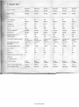
5. Technical Data
Super-Co.
Super-Co.
Super-Co.
Sport-Co_
Sport-Co.
Sport-Co.
433-002
433-<lO4
433-022
515-003
515-004
515-041
Engine Model
267-003
267-004
267-031
267·001
267-00'1.
267-032
Cubic Capacity
,.
50
49,9
,.
,.
49,9
39/41,8
39141,8
39141,8
39/41,B
39/41,8
39/41,8
Compression
8,5:1
8,5:1
8,5:1
8,5:1
8,5:1
8,5:1
Capacity, h. p.
2,6
2,6
2,'
2,'
2,6
2,6
R.P.M.
4500
4600
4830
4550
4600
4850
Mode of Operotion
2-stroke
2·stroke
2-stroke
2·stroke
2-stroke
2·stroke
Gearbox Oil
SAE 80
SAE80
SAE80
SAE 80
SAE80
SAE 80
Gearbox capacity, cc
3,.
3,.
350
350
350
350
Petroil mixture
1 :25
1:25
1:25
1:25
1:25
1:25
Oil grade for petroil mixlure
SAE40
2-stroke oil or
engine oil
SAE 40
2-slroke oil or
engine oil
2-slroke oil or
SAE 40
engine oil
2-slroke oil or
SAE40
engine oil
2-stroke oil or
SAE40
engine oil
2·stroke oil or
SAE40
engine oil
1,6 I
1,61
1,61
1,61
1,61
1,61
CarbureHor Model Code
1/16/60
1/16/60
1/16/60
1/16/60
1/16/60
1/16/60
Cross section
16
16
16
Main Jet
70
70
70
..
..
Needle Jet
2,20
2,20
2,20
2,17
2,17
2,20
3
3
3
3
3
3
Bosch
Bosch
6 V/23W
Bosch
6 V/23 W
Bosch
6 V/23W
6 V/23W
Bosch
6 V/23 W
Bosch
6 Vl23W
Ignition timing, before TOC
1,8mm
1,Bmm
1,8mm
1,8mm
1,8mm
1,8mm
Contact Breaker Gop
0,35-0,45
0,35-0,45
0,35--0,45
0,35-0,45
0,3S-0,4~
0,35-0,45
Machine Model
.,. Bore/Stroke
Rated fuel consumption
per 100 Itm
Needle setting,
~top
from lop
16
16
16
70
Idling Jet
Air Adjuster Screw
Electrical System
,
www.oudebromfiets.nl
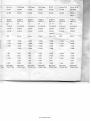
.
)rl-Co.
KS 50 Super
KS 50 Super
KS 50 Super
KS 100
Scooler R50
Scooler RS 50
-041
515-002
515-061
515-061
514-320
561-003
561-004/06
.()32
276..()Q2
276-026
276-026
281-320
267·020
276-010
276-44
,
50
49,9
49,9
98
49,9
49,9
39/41,8
39/41,8
39/41,8
50150
39/41,8
39/41,8
8,5:1
9:1
9:1
9:1
9:1
9:1
',2
',6
.~
8,2
2,6
',6
7200
6900
7500
6340
4500
7000
troke
2-stroke
2-stroke
2-slroke
2-slroke
2-stroke
2-stroke
EO>
SAE80
SAE80
SAEBO
SAE80
SAE 80
SAE80
350
350
350
'50
350
350
5
1 :25
1:25
1 :25
1:25
1 :25
1:25
Iroke oil or
2-stroke oil or
SAE40
engine oil
2-stroke oil or
SAE 40
engine oil
2-slroke oil or
SAE40
engine oil
2-slroke oil or
SAE40
engine oil
2-slroke oil or
SAE40
engine oil
2-slroke oil or
SAE40
engine oil
2,31
2,6'
2,6'
2,71
2,31
2,51
1117/61
1f17/64
1/17fl6
1/22/41
1/16163
1/17/62
17
17
17
22
16
17
82
84
82
100
68
70
2,24
2,24
2,15A
2,64
2,20
2,15A
2
3
2
3
3
2
41~
,1
•
E40
Jine oil
6I11J
)
•
1V
35
35
11h-2 IhU.
,,"/23W
Bosen
6 V/34 W
Bosch
6 V/34 W
Bosch
6 Vl34 W
mm
l,8mm
1,1 mm
1,1 mm
0,35-0,45
0,35--{),45
0,35-0,45
5-0,45
Bosch
6 Vl34 W
Bosch
6 Vl1B+5 W
Bosch
6 V129+5 W
1,8-2,0 mm
1,8mm
1,1 mm
0,35-0,45
0,35--{),45
,C/"-cq
\ 0,35--{),45
. ()/.f
www.oudebromfiets.nl
,
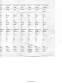
5. Technical Dato
Super-Co.
Super-Co.
Super-Co.
Sport-Co.
Sport-Co.
Sport-Co.
"l3-OO2
<J3.OO4
433-022
515.003
515-Q04
515-Q.41
Engine Model
267-003
267-004
267-031
267-001
267-002
267-032
Spark Plug
W22511
225/14u2
W22511
225fl4u2
W225T1
225/14u2
W22ST1
225/14 u 2
W225Tl
225f14u2
W22ST1
225/14 u 2
Spark Gap
0,5
0,5
0.'
0,5
0,5
0.4
6Vf15W
6V!15W
6 VlI5W
6V!15W
6V115W
6 Vf15 W
Rear light Bulb
6V13W
6V13W
6V13W
6V13W
6V13W
6V13W
Broke light Bulb
6V15W
6V/5W
6V/5W
6V/5W
6V15W
6V/5W
Bell
Bell
Bell
Bell
Bell
Bell
ht Gear
1:2,470
1 :2,470
1:2,470
1 :2,470
, 1 :2,470
1:2,470
2nd Gear
1 :1,476
1 :1,476
1:1,476
1:1,476
1 :1,476
1:1,476
3rd Gear
1:0,962
1:0,962
I-JJ,962
1:0,962
1 :0,962
1:0,962
151 Gear
1 :36,9
1:36,9
1 :36,9
1 :36,9
1:36,9
1 :36,9
2nd Gear
1:22,1
1 :22,1
1 :22,1
1,22,1
1:22,1
1:22,1
3rd Gear
1 :14,45
1:14,45
1 :14,45
1:14,45
1 :14,45
1 :14,45
Primary Reduction
1 :4,33
1:4,33
1:4,33
1 :4,33
1:4,33
1 :4,33
Clutch
Multi_plate
Oilboth Type
Multi·plote
Oil both Type
Multi.plote
Oilboth Type
Multi-plate
Oilboth Type
Multi-plate
Oilbath Type
Multi-plate
Oilbolh Type
Machine Model
'Headlight Bulb
Flashing Direction Indicators
Signal
Gear Ratios:
4th Gear
O ...el'(lll Tl'(lnmlinian Rellic
4th Gear
,
'.
_/
www.oudebromfiets.nl
:0.
Sport-Co.
KS 50 Super
KS 50 Super
KS 50 Super
K$ 100
Scooter R50
Scooter RS 50
515-041
515-002
515-061
515-061
514-320
561-003
561-004106
267-032
'll6-002
'll6.{)26
'll6-026
281-320
267.()2()
276..010
27......
f1
,2
W260Tl
W22STl
225/14 u 2
W260Tl
260114u2
W260Tl
26OIl4 u 2
W260Tl
W225Tl
W260Tl
260114 u 2
260114 u 2
225/14 u 2
26OII4u2
.p,'
0,5
0,'
0,'
0,4
0,'
0,'
oN
6VIl5W
6 V 25!25 W
6 V 25125 W
6 V 25125. W
6 V 25/25 W
6V115W
6 V 25115 W
,
6V13W
6V/3W
6V13W
6V13W
6V/5W
6V13W
6V13W
6V/5W
6V/5W
6V/5W
6V15W
6V/5W
6V/SW
6V/5W
Buzzer
,
.~IS
6 V/18W
,Iote
h Type
Bell
Bu~zer
Buzzer
Buzzer
Horn 17W
Bell
1:2,470
1:3,636
1:3,636
1:3,636
1 :3,636
1:2,466
1:1,476
1:2,058
1:2,058
1:2,058
1:2,058
1:1,476
1:2,058
1,0,962
1 :1;M3
1,1,363
1 :1,363
1 :1,363
1:0,961
1 :1,363
1:1,ClSO
1:1,080
1 :1,090
1 :1,011O
1:36,9
1:35,4
1:35,4
1 :26,00
1:26-69
1:26,8,4
1:22,1
1 :20.1
'''5"
1:20,1
1:20,1
1:14,75
1 :15,97
1:15,19
1,14,45
1:13,2
1:13,2
1:13,2
1:9,n
1:10,41
T:10,06
1:10.,5
1:10,5
1 :10,5
1:7,74
1:4,33
1 A,33
1:4,33
1 A,33
, :2,785
1 :4,33
1 :4,33
Multi-plate
Oilboth Type
Multi-plate
Oilboth Type
Multi.plate
Oilboth Type
Multi-plate
Oilboth Type
Multi-plate
Oilbath Type
Multi-plate
Oilbath Type
Multi-plate
Oil bath Type
I
,
,
www.oudebromfiets.nl
,
1,3,636
1:1,080
1:7,97