1
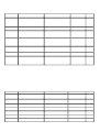
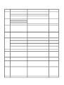
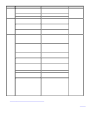
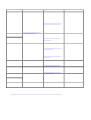
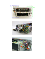
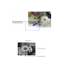
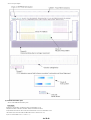
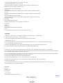
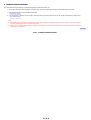
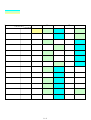
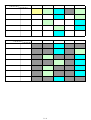
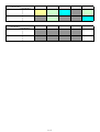
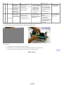
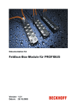
PIXMA iP8500
SERVICE
MANUAL
Canon
Copyright 2004, Canon U.S.A. This technical publication is the proprietary and confidential information of Canon U.S.A. which
shall be retained for reference purposes by Authorized Service Facilities of Canon U.S.A. Its unauthorized use is prohibited.
(3) Grease application
::w::w:
Part name
Chassis
Where to apply grease / oil
Grease / oil name
Grease / oil
amount
1
Entire surface the carriage slider contacts
FLOIL KG107A
3 drops
2
Cam contact portion (at 3 locations)
FLOIL KG107A
1 drop
3
Coil spring inner surface contact portion
MOLYKOTE HP300
1 drop
Lift gear 2
4
Coil spring contact portion
MOLYKOTE HP300
1 drop
Chassis
5
Carriage shaft left end sliding portion
FLOIL KG107A
1 drop
6
Carriage shaft cam L sliding portion
MOLYKOTE HP300
2 drops
7
Carriage shaft sliding portion on the left side of the chassis (at 2
locations)
FLOIL KG107A
1 drop
8
Carriage shaft cam L contact portion (at 2 locations)
FLOIL KG107A
2 drops
9
Carriage shaft cam R sliding portion
MOLYKOTE HP300
1 drop
10
Carriage shaft right end sliding portion
FLOIL KG107A
1 drop
11
Carriage shaft right end contact portion
FLOIL KG107A
1 drop
Carriage shaft
12
Entire surface of the carriage shaft where the carriage unit slides
EU-1
80±30mg
Carriage shaft spring L
13
Carriage shaft sliding portion (over the area more than 2/3 from the
top end of the spring)
FLOIL KG107A
1 drop
Transmission gear
14
Inner surface
MOLYKOTE HP300
1 drop
Feed roller ass'y
15
Bushing where the spring contacts
FLOIL KG107A
Half drop
Lift shaft
16
Spring sliding portion (4 locations)
FLOIL KG107A
1 drop
17
Pressure roller ass'y contact portion (4 locations)
FLOIL KG107A
1 drop
18
Entire inner surface where the oil pad fits in
EU-1
100 +/- 10mg
19
Entire inner surface where the oil pad fits in
EU-1
100 +/- 10mg
Carriage unit
Note: 1 drop = 9 to 18 mg
To the top
<Part 1: 3. REPAIR, 3-3 (1) to (3)>
::w::w::
(4) Waste ink counter setting
When the logic board ass'y is replaced, reset the waste ink counter. In addition, according to the waste ink amount, replace the waste ink absorber (the bottom
case unit or the ink absorbers). The standard amount for waste ink absorber replacement is given in the table below.
Waste ink amount*1
Bottom case unit or ink absorber replacement
Less than 7%
Not required.
7% or more
Required.
*1: Check the waste ink amount by service test print or EEPROM information print.
[See 3.3. Adjustment / Settings, (6) Service mode, for details.]
(5) User mode
Function
Procedures
Remarks
Print head manual cleaning
- Cleaning both black and color:
See "Standalone printer operation" below.
- Cleaning black or color separately, or both black and color:
Perform from the printer driver's Maintenance tab.
Print head deep cleaning
- Cleaning black or color separately, or both black and color:
Perform from the printer driver's Maintenance tab.
Paper feed roller cleaning
See "Standalone printer operation" below.
Nozzle check pattern printing
See "Standalone printer operation" below.
Also available from the printer driver's
Maintenance tab.
Print head alignment
See "Standalone printer operation" below.
In Custom Settings of the printer driver's
Maintenance tab, manual print head alignment (by
selecting the optimum values) as with the
conventional models can be performed.
Bottom plate cleaning
Perform from the printer driver's Maintenance tab.
Cleaning of the platen ribs when the back side of
paper gets smeared.
CD-R print position adjustment
Perform from the application software.
Ink tank replacement
Open the access cover. When the carriage stops at the center,
an ink tank can be replaced.
Print head replacement
The print head is replaceable at the same position as for ink
tank replacement. (Open the access cover. When the carriage
stops at the center, the print head can be replaced.)
<Standalone printer operation>
1) Turn on the printer.
2) Press and hold the Resume/Cancel button until the LED blinks the specified number of times listed in the table below, and release it. The operation starts.
LED blinking
Operation
Remarks
1 time
Print head manual cleaning
2 times
Nozzle check pattern printing
3 times
Paper feed roller cleaning
4 times
Automatic print head alignment
Set a sheet of plain paper (A4 or letter) in the ASF.
5 times
Bottom plate cleaning
Fold a sheet of plain paper (A4 or letter) in half crosswise, then unfold and set it in the
ASF with the folded ridge facing down.
6 times
Unspecified
7 times
Set the widest head-to-paper distance
Set a sheet of plain paper (A4 or letter) in the ASF or the cassette (according to the
Paper Feed switch setting).
(6) Service mode
Function
Procedures
Remarks
Service test print
- Model name
- ROM version
- Waste ink amount
- CD-R sensor correction
See "Service mode operation procedures" below.
Set a sheet of A4- , letter-, or larger-sized paper.
For print sample, see 3-4. Verification Items, (1) Service test
print, <Service test print sample>.
EEPROM initialization
See "Service mode operation procedures" below.
The following items are NOT initialized:
- USB serial number
- Destination settings
- Waste ink counter
- CD-R correction value
Waste ink counter reset
See "Service mode operation procedures" below.
If the waste ink amount is 7% or more, replace the bottom case
unit, or the ink absorbers.
Destination settings
See "Service mode operation procedures" below.
Other than Japan: iP8500
Japan: iP8600
Note: At the end of the service mode, press the Power button. To protect the media sensor from being dislocated during transportation, the paper lifting plate
of the sheet feeder unit will be raised.
::w::w::
<Service mode operation procedures>
1) With the printer power turned off, while pressing the Resume/Cancel button, press and hold the Power button. (DO NOT release the buttons. The LED lights
in green to indicate that a function is selectable.)
2) While holding the Power button, release the Resume/Cancel button. (DO NOT release the Power button.)
3) While holding the Power button, press the Resume/Cancel button 2 times, and then release both the Power and Resume/Cancel buttons. (Each time the
Resume/Cancel button is pressed, the LED lights alternately in orange and green, starting with orange.)
4) When the LED lights in green, press the Resume/Cancel button the specified number of time(s) according to the function listed in the table below. (Each time
the Resume/Cancel button is pressed, the LED lights alternately in orange and green, starting with orange.)
Time(s)
LED
0 times
Green
Power off
When the print head is not installed, the carriage returns and
locks in the home position.
1 time
Orange
Service test print
See 3-4. Verification Items, (1) Service test print.
2 times
Green
EEPROM information print
See 3-4. Verification Items, (2) EEPROM information print.
3 times
Orange
EEPROM initialization
4 times
Green
Waste ink counter resetting
5 times
Orange
Destination settings
6 times
Green
Print head deep cleaning
7 times
Green
CD-R test print
Not used in servicing.
8 times
Orange
CD-R print position correction
(horizontal)
Not used in servicing.
9 times
Green
CD-R print position correction
(vertical)
Not used in servicing.
10 times or more
Function
Remarks
Proceed to the step 5), and follow the Destination settings
procedures.
Return to the menu selection
5) After the function (menu) is selected, press the Power button. The LED lights in green, and the selected function is performed. (When the operation
completes, the printer returns to the menu selection mode automatically.)
<Destination settings procedures>
In the destination settings mode, press the Resume/Cancel button the specified number of time(s) according to the destination listed in the table below, and press
the Power button.
Time(s)
1 time
LED
Destination
Orange
Japan: iP8600
2 times
Green
Other than Japan, non-support of CD-R printing (A4): iP8500
3 times
Orange
Other than Japan, non-support of CD-R printing (LTR): iP8500 (LTR)
4 times
Green
Other than Japan, support of CD-R printing (A4): iP8500
5 times
Orange
Other than Japan, support of CD-R printing (LTR): iP8500 (LTR)
6 times or
more
Return to the menu selection
Note: After setting the destination, confirm the model name in service test print or EEPROM information print.
[See 3.4. Verification Items, (1) Service test print, or (2) EEPROM information print.]
To the top
<Part 1: 3. REPAIR, 3-3 (4) to (7)>
::w::w::
3-4. Verification Items
(1) Service test print
<Print check items>
On the service test print (sample below), confirm the following items:
- Check 1, top of form accuracy: The line shall not extend off the paper.
- Check 2, EEPROM information
- Check 3, nozzle check pattern: Ink shall be ejected from all nozzles
- Check 4, halftone: There shall be no remarkable streaks or unevenness.
- Check 5, uneven printing due to carriage movement: There shall be no remarkable streaks or unevenness.
- Check 6, vertical straight lines: The line shall not be broken.
- Check 7, CD-R detection sensor light volume correction / automatic print head alignment: The results shall be OK.
- Check 8, index pattern: The patterns shall be printed in multiple levels (stepped).
- Check 9, model name: iP8500 for non-Japan model, iP8600 for Japan model.
::w::w::
<Service test print sample>
(2) EEPROM information print
<How to read EEPROM information print>
Print sample:
iPXXXX V1.00 IF(USB1=1 USB2=0) D=004.5 ST=2004/06/27-18:30
ER(ER0=1000 ER1=5100 ER2=1300 ER3=5B00) LPT=2004/07/09-09:09
PC(M=002 R=000 T=001 D=009 C=000) CLT0=2004/06/27-18:30 CLT1=2004/06/27-18:30
CH=00002 CT(G=001 R=001 PM=002 BK=002 PC=005 C=000 M=01 Y=01)
IS(G=1 R=1 PM=0 BK=1 PC=1 C=1 M=1 Y=1)
::w::w::
IC(G=028 R=028 PM=028 BK=201 PC=028 C=182 M=169 Y=249)
P_ON(S=00009 H=005 A=000) A_REG=1 M_REG=0
UR(A(Goe)=+01 B(Roe)=-01 C(PMoe)=+01 D(Bkoe)=-01 E(PCoe)=+01 F(Coe)=+01 G(Moe)=+01
H(Bkbi)=+01 I(Cbi)=+01 J(Mbi)=+01 K(BkCLbi)=+01)
WP=0024 CDIN(LG=001 PB=000) MSD(49710)
TPAGE=1500
PAGE(All=00083 PP=00035 HR+MP=00003 PR+SP+SG =00000 GP =00000 PC=00000 ENV=00000
L=5 2L=0)
UCPAGE(All=00083 PP=00035 HR+MP=00003 PR+SP+SG =00000 GP =00000 PC=00000 ENV=00000
L=5 2L=0)
BPPAGE(All=00083 BSSP=00003 PC=00000)
CDPAGE(All=000 A4=000 L=000 2L=000 PC=000 OTR=000) EDGE(ALL=00083 PC=000 UPC=000
OTR=000 UOTR=000)
CDR=00000
CDRP=(-00005,-00029) CDRS=(000)
Head Temp =18.5 Head Temp 1=17.5 Env Temp=30.0 FF (3F 3F 3F):w
HDEEPROM
V0001
SN=a9850000
LN(00000 00000 00015 00015 00015 00015 00015)
ID=01
IL=(G=00 R=00 PM=00 BK=00 PC=00 C2=00 M2=00 Y=00 M1=00 C1=00)
Printed items:
1. Model name 2. ROM version 3. Connected I/F (USB1/USB2) 4. Waste ink amount 5. Installation date
6. Operator call/service call error record 7. Last printing time
8. Purging count (manual/deep cleaning/timer/dot count/ink tank or print head replacement)
9. Cleaning time (CLT0/CLT1)
10. Print head replacement count 11. Ink tank replacement count (dye G/R/PM/BK/PC/C/M/Y) 12. Ink status (dye G/R/PM/BK/PC/C/M/Y)
13. Total ink consumption (G/R/PM/BK/PC/C/M/Y)
14. Power-on count (soft/hard/auto) 15. Automatic print head alignment by user 15-1. Manual print head alignment by user
16. User print head alignment values (Goe/Roe/PMoe/Bkoe/PCoe/Coe/Moe/Bkbi/Cbi/Mbi/BkCLbi)
17. Wiping count 18. Camera Direct Print-supported device connection record 19. Longest period where printing stops 20. Total print pages
21. ASF feed pages (total, plain paper, High Resolution Paper & Matte Photo Paper, Photo Paper Pro & Photo Paper Plus Glossy & Photo Paper Plus Semi-gloss,
Glossy Photo Paper, postcard, envelope, L-size & 4x6, 2L-size & 5x7)
22. U-turn cassette feed pages (total, plain paper, High Resolution Paper & Matte Photo Paper, Photo Paper Pro & Photo Paper Plus Glossy & Photo Paper Plus
Semi-gloss, Glossy Photo Paper, postcard, envelope, L-size & 4x6, 2L-size & 5x7)
23. Auto duplex print pages (total, Photo Paper Plus Double Sided, postcard)
24. Camera Direct print pages (total, A4 & LTR, L-size & 4x6, 2L-size & 5x7, postcard, other)
25. Borderless print pages (total, postcard via ASF, postcard via U-turn cassette, other via ASF, other via U-turn cassette)
26. Number of CD-Rs printed
27. CD-R print position adjustment 28. CD-R sensor correction value 29. Print head temperature (chip 0 for G/R/PM/BK/PC, chip 1 for C/M/Y)
30. Inside temperature 31. Line inspection information
HDEEPROM
32. Version
33. Serial number
34. Lot number
35. Print head ID
36. Ink ejection level (BK/PM/PC/M/C/Y/G/R)
To the top
<Part 1: 3. REPAIR, 3-4>
::w::w::
4. PRINTER TRANSPORTATION
This section describes the procedures for transporting the printer for returning after repair, etc.
1) In the service mode, press the Power button to finish the mode, and confirm that the paper lifting plate of the sheet feeder unit is raised.
2) Keep the print head and ink tanks installed in the carriage.
[See Caution 1 below.]
3) Turn off the printer to securely lock the carriage in the home position. (When the printer is turned off, the carriage is automatically locked in place.)
[See Caution 2 below.]
Caution:
(1) If the print head is removed from the printer and left alone by itself, ink (especially the pigment black ink) is likely to dry. For this reason, keep the
print head installed in the printer even during transportation.
(2) Securely lock the carriage in the home position, to prevent the carriage from moving and applying stress to the carriage flexible cable, or causing ink
leakage, during transportation.
To the top
<Part 1: 4. PRINTER TRANSPORTATION>
::w::w::
Part 2
TECHNICAL REFERENCE
1. NEW TECHNOLOGIES
(1) Larger color space by 8 colors of ink (6 colors + red + green)
By adding the red and green ink, a larger color space than the 6-color printer is available.
(2) Highest in class print speed
By increasing the print head drive frequency by 20% over conventional printers, further improvement in photo print speed has been achieved.
(3) Multi-paper path functionality (ASF, front cassette, CD-R printing*, automatic duplex printing) as a standard feature
- Cassette: Except Photo Stickers and credit card size, same types and sizes of paper as the sheet feeder, including photo papers, are supported.
- Sheet feeder: Photo Stickers and credit card size are supported.
* Support of CD-R printing differs according to region.
(4) New design
A new generation printer design by complete renovation of styling has been adopted.
(5) Automatic creation of a photo album
By using Photo Paper Plus Double Sided and dedicated application software, a photo album can be created automatically.
(6) CD-R direct printing without using the CD-R tray feeder (applicable only to specific regions)
By incorporating CD-R tray feeder functionality into the printer, CD-R direct printing can be performed without using a CD-R tray feeder.
(7) Automatic duplex printing unit installed as a standard feature
For the following paper types and sizes, automatic duplex printing can be performed:
- Type: Plain paper, Super White Paper, Photo Paper Plus Double Sided
- Size: A5, B5, 5" x 7", A4, LTR
(8) Automatic print head alignment
The simple print head alignment featured in the i990 is automatically performed. At connection to a computer, or at Camera Direct Printing, the print head can
be adjusted automatically, freeing users from performing the simple print head alignment.
Manual print head alignment is available in the printer driver's Maintenance sheet's Custom Settings.
To the top
<Part 2: 1. NEW TECHNOLOGIES>
::w::w:
2. CLEANING MODE AND AMOUNT OF INK PURGED
To prevent printing problems due to bubbles, dust, or ink clogging, print head cleaning is performed before the start of printing, except in the following cases:
- Cleaning on arrival: Performed when the access cover is closed.
- Cleaning by dot count: Performed after ejection of paper (or after printing on the back side of paper when auto duplex printing is performed).
<Cleaning mode list>
Condition
Details
Amount of ink used (g)
Est. required time (sec.)
On arrival of the printer
(All at the same time)
First cleaning after shipped from the plant.
2.17
84
Dot count cleaning
When the specified number of dots are printed since the previous
cleaning. (Number of ejected ink droplets in each line of nozzles
is counted, and addd to the number of dots.)
0.79 (G/R/PM/BK/PC)
0.59 (C/M/Y)
67
Timer cleaning - 0
If 120 to 480 hours have elapsed since the previous cleaning till
the start of the next printing.
0.79 (G/R/PM/BK/PC)
0.59 (C/M/Y)
67
Timer cleaning - 1
If 480 or longer hours have elapsed since the previous cleaning till 1.87 (G/R/PM/BK/PC)
the start of the next printing.
1.37 (C/M/Y)
83
At print head replacement -1
(All at the same time)
When the same print head (same print head serial number) is
removed and installed.
1.87 (G/R/PM/BK/PC)
1.37 (C/M/Y)
83
At print head replacement -2
(All at the same time)
When the print head is removed, and a new print head is installed. 2.17 (G/R/PM/BK/PC)
1.56 (C/M/Y)
84
At ink tank replacement - 1
(All at the same time)
When more than 1 ink tanks are replaced without removing and
installing the print head.
67
At ink tank replacement - 2
(Each color)
When replacement of an ink tank is detected*1 , and when ink tank 0.94 (BK/PM)
0.94 (PC/R)
replacement is performed without removing and installing the
print head, cleaning for the detected color(s) is conducted.
0.94 (G)
0.78 (C)
0.78 (M)
0.78 (Y)
67
68
69
67
68
69
Manual cleaning -1
(All at the same time)
- Via the operation panel (All at the same time only)
- Via the printer driver
0.79 (G/R/PM/BK/PC)
0.59 (C/M/Y)
67
Manual cleaning -2
(Each color)
Via the printer driver
0.94 (G/R/PM/BK/PC)
0.78 (C/M/Y)
68
69
Via the printer driver
Deep cleaning
(All at the same time/Each color)
1.87 (G/R/PM/BK/PC)
1.37 (C/M/Y)
83
If the print head has not been
capped before power-on
(All at the same time)
1.87 (G/R/PM/BK/PC)
1.37 (C/M/Y)
83
0.79 (G/R/PM/BK/PC)
0.59 (C/M/Y)
*1: After the print head moves to the ink tank replacement position at low ink detection,
- when the raw ink amount changes from low to high, the applicable ink tank is considered to have been replaced.
- when the raw ink amount changes from high to low, or the raw ink amount stays unchanged (high or low), it is considered that ink tanks are
not replaced.
To the top
<Part 2: 2. CLEANING MODE AND AMOUNT OF INK PURGED>
::w::w:
<--
2-3
-->
<--
-->
<--
-->
2-4
<--
-->
<--
-->
2-5
4. FAQ (Problems Specific to the iP8500 and Corrective Actions)
No.
*
Function
Phenomenon
Margin (approx.
0.3mm)
1
C
Print results
Condition
Cause
- Paper feeding from the
cassette, Photo Paper Plus
Double Sided (A4),
borderless printing, printing
on the back side of paper
- In the printer driver,
increase the amount of
extension.
- Change the paper feeding
method from the cassette
to the auto sheet feeder.
- In the low temperature and
low humidity environment
- Skewed paper
feeding
2
B
Print results
- Printing on the
platen
Corrective action
- Plain paper
- In the high temperature and
high humidity environment
Possible call or
complaint
- A margin appears on
printouts.
- Paper feeds at an
angle.
- If paper is curled,
straighten it.
- Paper feeds at an
angle.
- Try printing on the other
side of paper.
- Printing is performed
on the platen.
- The back side of
paper gets smeared.
Variation in the top
of form accuracy
3
B
Print results
B
Print results - Margin
Soiling on the back
side of paper (lines
or streaks parallel to
the paper feed
direction)
5
A
- In the low temperature and
low humidity environment
- Not solved even when the
number of sheets stacked in
the auto sheet feeder or the
cassette is reduced
- Skewed paper
feeding
4
- A5 or legal size
- Photo Paper Plus Double
Sided
- 2L size (Japan only)
6
B
- Change the paper feeding
method from the cassette
to the auto sheet feeder.
- After continuous borderless
printing of small sized paper
(such as 4 x 6), when a
larger sized paper (such as
A4) is printed.
Soiling on paper in
- Automatic duplex printing
automatic duplex
(Photo Paper Plus Double
printing (lines or
Sided, postcards, plain
streaks perpendicular
paper)
to the paper feed
direction)
- Set the top margin to 4mm - Print start position
or more.
varies.
- In the printer driver,
increase the amount of
extension.
- With Photo Paper Plus
Double Sided or postcards,
the phenomenon is likely to
be noticeable and to be
complained of by users, as
printing is performed on
both sides of such paper.
Print results
Due to decrease of paper
feed capability in the low
temperature and low
humidity environment
- A margin appears on
printouts.
- Paper feeds at an
angle.
In borderless printing,
1. Perform Bottom plate
printing is performed to the
cleaning (from the
size slightly larger than the
printer driver) up to 3
paper size, and ink off the
times*1.
paper is absorbed by the
2. If soiling on the paper
platen's ink absorber.
still remains after 3
Absorbed ink may attach to
times of Bottom plate
the platen rib(s) after
cleaning, wipe the
several dozen sheets are
platen rib(s) and their
printed, causing soiling at
surroundings with a
the leading edge of paper
cotton swab.
or on the back side of
paper.
- Paper gets smeared.
On the rib(s) inside the
sheet feed unit used for
duplex printing, ink mist
may accumulate, smearing
paper.
- Paper gets smeared.
Temporary operational
solution:
- The back side of
paper gets smeared.
- The back side of
paper gets smeared.
Cancel automatic duplex
printing, and manually print - Even after Bottom
each side of paper.
plate cleaning was
performed, and the
platen ribs were
Cleaning by user:
cleaned with cotton
1. Perform Bottom plate
swab, paper gets
cleaning (from the
smeared.
printer driver) up to 3
*1
times .
2. If soiling on the paper
still remains after 3
times of Bottom plate
cleaning, wipe the
platen rib(s) and their
surroundings with a
cotton swab.
Print results
If the phenomenon persists
after conducting 1 and 2,
servicing is required.
Service:
Wipe any soiling or dirt off
from the sheet feed unit and
the bottom case unit ribs*2.
Scratches on paper
7
C
Print results
- PP-101D, PP-101, PR-101,
SG-101, etc.
- Paper feeding from the
cassette
Scratches on the PF return
lever due to paper feeding
from the cassette, and
duplex printing path.
- Multiple number of sheets
loaded
::w::w:
- Change the paper feeding
method from the cassette
to the auto sheet feeder.
- If automatic duplex
printing is performed,
cancel it, and, by setting
only a single sheet of
paper in the auto sheet
feeder, manually print
- Paper is scratched.
- Marks appear on
printed paper.
each side of paper.
8
9
C
C
Streaks or uneven
printing at the
leading edge (from
top to approx. 3mm
down) or at the
Print results
trailing edge (from
the bottom up to
approx. 18mm) on
specialty paper in
grayscale printing
Print results
Only when all the following
conditions are met:
- If paper is curled, the
- Cancel grayscale printing, - Lines or uneven
leading or trailing edge
and print in colors.
printing at the top or
contacts the ink absorber, - To print color image in
bottom of paper
- Specialty paper (PR, SP, SG,
preventing the dot
gray, change the image
MP GP, etc.)
placement accuracy,
color in gray using the
- Grayscale printing
resulting in uneven
application, then print it
printing or streaks.
in colors.
- Paper is curled.
- Uneven printing at the
- Straighten the paper.
trailing edge.
Uneven printing at
Only when both the following
the trailing edge
conditions are met:
(from the bottom end
- Photo Paper Plus Double
to approx. 20mm up)
Sided (PP-101D)
- Printing in dark flat color
Incorrect bidirectional
positioning of the print
head. (Inaccuracy in ink
droplet placement at the
trailing edge)
Perform print head
alignment.
- Perform automatic print
head alignment.
Color hue differs (or
printing is uneven) in
the bottom area.
- If the problem is not
solved by automatic print
head alignment, perform
manual print head
alignment.
*1: Change the paper in each Bottom plate cleaning. The cleaning can end when paper does not get any soiling.
*2: Locations to clean in servicing when soiling on paper in automatic duplex printing persists:
* Occurrence level:
A: The symptom is likely to occur frequently. (Caution required)
B: The symptom may occur under certain conditions, but likeliness is assumed very low in practical usage.
C: The symptom is unlikely to be recognized by the user, and no practical issues are assumed.
To the top
<Part 2: 4. FAQ>
::w::w: