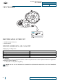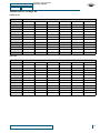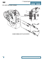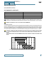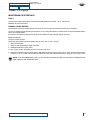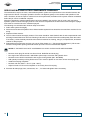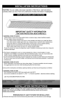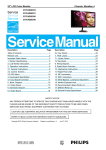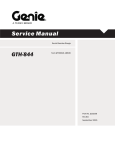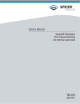
1
Service Manual Transmission T12000 3, 4, & 6-speed Intermediate Drop VDT12000 VDT 17° TSM-0022 April 2011 T12000, VDT & 17° 05042011 1 MOT12000T20 Maintenance and Repair manual and installation guide T12000, VDT & 17° 05042011 MOT12000T20 NOTICE ................................................................................................................................. 1 FOREWORD ..................................................................................................................................1 TOWING OR PUSHING .................................................................................................................1 SAFETY PRECAUTIONS ..............................................................................................................1 CLEANING AND INSPECTION ............................................................................................ 2 CLEANING .....................................................................................................................................2 BEARINGS ................................................................................................................................................ 2 HOUSINGS ................................................................................................................................................ 2 INSPECTION .................................................................................................................................2 BEARINGS ................................................................................................................................................ 2 OIL SEALS, GASKETS, ETC. ................................................................................................................... 2 GEARS AND SHAFTS ............................................................................................................................... 3 HOUSINGS, COVERS, ETC. .................................................................................................................... 3 TECHNICAL SPECIFICATION ............................................................................................. 4 T12000 - 3,4,6 speed .....................................................................................................................4 IDENTIFICATION OF THE UNIT ...................................................................................................4 WEIGHT, DIMENSIONS, OIL CAPACITY .....................................................................................4 PRESSURE AND TEMPERATURE SPECIFICATIONS ........................................................................... 5 ELECTRICAL SPECIFICATIONS .............................................................................................................. 5 HYDRAULIC COOLER AND FILTER LINE SPECIFICATIONS ................................................................ 5 VDT12000 ......................................................................................................................................6 IDENTIFICATION OF THE UNIT ...................................................................................................6 WEIGHT, DIMENSIONS, OIL CAPACITY .....................................................................................6 TRANSMISSION WITH A 3 SHAFT DROP BOX ...................................................................................... 6 TRANSMISSION WITH A 4 SHAFT DROP BOX ...................................................................................... 7 VDT 17 DEGREES .........................................................................................................................8 IDENTIFICATION OF THE UNIT ...................................................................................................8 WEIGHT, DIMENSIONS, OIL CAPACITY .....................................................................................8 TIGHTENING TORQUES ..............................................................................................................9 COIL AND CARTIDGE TORQUE .............................................................................................................. 10 MAINTENANCE .................................................................................................................... 11 OIL SPECIFICATIONS ...................................................................................................................11 RECOMMENDED LUBRICANTS .............................................................................................................. 11 VALID FOR: VDT12000 & T12000 .......................................................................................................................12 VALID FOR: T12000 .............................................................................................................................................12 T12000 - 3, 4, 6 speed ...................................................................................................................13 MAINTENANCE INTERVALS .................................................................................................................... 13 DAILY ...................................................................................................................................................................13 NORMAL DRAIN PERIOD ...................................................................................................................................13 SERVICING MACHINE AFTER COMPONENTS OVERHAUL ................................................................. 14 VDT12000 ......................................................................................................................................15 MAINTENANCE INTERVALS FOR THE 3 & 4 SHAFT DROP BOX ......................................................... 15 DAILY ...................................................................................................................................................................15 NORMAL DRAIN PERIOD ...................................................................................................................................15 MAINTENANCE INTERVALS FOR THE TRANSMISSION. ...................................................................... 15 INSTRUCTIONS FOR LINING REPLACEMENT AND ADJUSTMENT OF PARKING BRAKE ASSEMBLY .................................................................................................................................................16 ASSEMBLY DIAGRAM .............................................................................................................................. 16 DISASSEMBLY .......................................................................................................................................... 17 ASSEMBLY ................................................................................................................................................ 18 Maintenance and Repair manual and installation guide 2 T12000, VDT & 17° 05042011 MOT12000T20 TROUBLESHOOTING GUIDE ............................................................................................. 22 T12000 - 3, 4, 6 speed .................................................................................................................. 22 T12000 TRANSMISSION ........................................................................................................................... 22 TROUBLESHOOTING PROCEDURES ..................................................................................................... 22 STALL TEST ........................................................................................................................................................ 22 TRANSMISSION PRESSURE CHECKS ............................................................................................................. 22 MECHANICAL AND ELECTIRCAL CHECKS ...................................................................................................... 23 HYDRAULIC CHECKS ........................................................................................................................................ 23 TROUBLESHOOTING GUIDE ................................................................................................................... 24 LOW CLUTCH PRESSURE ................................................................................................................................. 24 LOW CHARGING PUMP OUTPUT ..................................................................................................................... 24 OVERHEATING ................................................................................................................................................... 24 NOISY CONVERTER .......................................................................................................................................... 24 LACK OF POWER ............................................................................................................................................... 24 CHECK POINTS ........................................................................................................................................ 25 ELECTRICAL WIRING ............................................................................................................................... 28 3-SPEED TRANSMISSION ................................................................................................................................. 28 STANDARD 4-SPEED TRANSMISSION (1-3-5 § 6 SPEED) .............................................................................. 29 ALTERNATIVE 4-SPEED TRANSMISSION (1-3-4-5 § 6 SPEED) ...................................................................... 30 6-SPEED TRANSMISSION ................................................................................................................................. 30 SPEED SENSOR - STATIC STANDALONE TEST ................................................................................... 31 VDT 12000 .................................................................................................................................... 32 CHECK POINTS ........................................................................................................................................ 32 TRANSMISSION WITH A 3 SHAFT DROP BOX ................................................................................................ 32 TRANSMISSION WITH A 4 SHAFT DROP BOX ................................................................................................ 35 VDT 17 DEGREES ........................................................................................................................ 38 CHECK POINTS ........................................................................................................................................ 38 SECTIONAL VIEWS AND PARTS IDENTIFICATION ......................................................... 39 T12000 .......................................................................................................................................... 39 GROUP - CONVERTER HOUSING .......................................................................................................... 39 GROUP -TRANSMISSION CASE AND PLATE ......................................................................................... 41 GROUP - TORQUE CONVERTER ............................................................................................................ 43 GROUP - PUMP DRIVE ............................................................................................................................ 44 GROUP - CHARGING PUMP .................................................................................................................... 45 GROUP - REVERSE IDLER ...................................................................................................................... 46 GROUP - FORWARD AND REVERSE SHAFT ......................................................................................... 47 GROUP - 3RD SHAFT (FOR 3-SPEED TRANSMISSION ONLY) ............................................................ 49 GROUP - HIGH (4TH) AND 3RD SHAFT .................................................................................................. 51 GROUP - 1ST AND 2ND SHAFT ............................................................................................................... 53 GROUP - OUTPUT SHAFT (REAR ONLY) ............................................................................................... 55 GROUP - OUTPUT SHAFT (FRONT ONLY) ............................................................................................. 56 GROUP - OUTPUT SHAFT (FRONT & REAR) ......................................................................................... 57 GROUP - DISK BRAKE ............................................................................................................................. 58 GROUP - CALIPER ASSEMBLY ............................................................................................................... 59 GROUP - ELECTRIC CONTROL .............................................................................................................. 61 GROUP - DRIVE PLATE ........................................................................................................................... 63 VDT 12000 .................................................................................................................................... 64 TRANSMISSION CASE & PLATE GROUP ............................................................................................... 64 3 SHAFT DROP BOX GROUP .................................................................................................................. 66 4 SHAFT DROP BOX GROUP .................................................................................................................. 67 T12000 INSTALLATION DETAILS ...................................................................................... 69 CONVERTER DRIVE COUPLING ................................................................................................ 69 TRANSMISSION TO ENGINE INSTALLATION PROCEDURE .................................................... 70 3 Maintenance and Repair manual and installation guide T12000, VDT & 17° 05042011 MOT12000T20 EXTERNAL PLUMBING .................................................................................................................71 OPTIONAL REMOTE FILTER ................................................................................................................... 72 COOLER & FILTER LINES SPECIFICATIONS ......................................................................................... 72 SPEED SENSOR INSTALLATION ................................................................................................73 OPERATION OF THE T12000 TRANSMISSION ................................................................. 75 THE TRANSMISSION ASSEMBLY ...............................................................................................75 THE CONVERTER, PUMP DRIVE SECTION AND PRESSURE REGULATING VALVE ........................ 76 THE INPUT SHAFT AND DIRECTIONAL CLUTCHES ............................................................................. 77 THE RANGE CLUTCHES .......................................................................................................................... 78 THE OUTPUT SECTION ........................................................................................................................... 78 THE TRANSMISSION CONTROLS (REFER TO HYDRAULIC DIAGRAM) ............................................. 79 ELECTRIC SOLENOID CONTROLS .............................................................................................80 3-SPEED TRANSIMISSION ...................................................................................................................... 80 3-SPEED TRANSMISSION ....................................................................................................................... 80 STANDARD 4-SPEED TRANSMISSION (1, 3, 5, 6 § 6-SPEED) .........................................................................80 ALTERNATIVE 4-SPEED TRANSMISSION, MODEL T12496 ONLY (1, 3, 4, 5 § 6-SPEED) .............................80 6-SPEED TRANSMISSION ....................................................................................................................... 81 POWERFLOWS, ACTIVATED SOLENOIDS AND HYDRAULIC CIRCUIT ...................................82 3-SPEED TRANSMISSION ....................................................................................................................... 82 NEUTRAL AND 3RD CLUTCH ENGAGED ..........................................................................................................82 FORWARD 1ST SPEED ......................................................................................................................................84 FORWARD 2ND SPEED ......................................................................................................................................86 FORWARD 3RD SPEED ......................................................................................................................................88 REVERSE 1ST SPEED ........................................................................................................................................90 4-SPEED TRANSMISSION ....................................................................................................................... 92 STANDARD 4-SPEED TRANSMISSION .............................................................................................................92 ALTERNATIVE 4-SPEED TRANSMISSION ........................................................................................................105 6-SPEED TRANSMISSION ....................................................................................................................... 117 NEUTRAL AND 3RD CLUTCH ENGAGED ..........................................................................................................117 FORWARD 1ST SPEED ......................................................................................................................................119 FORWARD 2ND SPEED ......................................................................................................................................121 FORWARD 3RD SPEED ......................................................................................................................................123 FORWARD 4TH SPEED ......................................................................................................................................125 FORWARD 5TH SPEED ......................................................................................................................................127 FORWARD 6TH SPEED ......................................................................................................................................129 REVERSE 1ST SPEED ........................................................................................................................................131 GEAR AND CLUTCH LAY-OUT (3-SPEED)...................................................................................133 GEAR AND CLUTCH LAY-OUT (4-SPEED AND 6-SPEED) .........................................................134 ASSEMBLY INSTRUCTION ................................................................................................. 135 T12000 - 3, 4, 6 speed ...................................................................................................................135 TRANSMISSION COMPLETE ................................................................................................................... 141 DISASSEMBLY ....................................................................................................................................................141 ASSEMBLY ..........................................................................................................................................................155 1ST CLUTCH ............................................................................................................................................. 172 DISASSEMBLY ....................................................................................................................................................172 ASSEMBLY ..........................................................................................................................................................176 2ND CLUTCH ............................................................................................................................................ 182 DISASSEMBLY ....................................................................................................................................................182 ASSEMBLY ..........................................................................................................................................................187 4TH CLUTCH ............................................................................................................................................. 194 DISASSEMBLY ....................................................................................................................................................194 ASSEMBLY ..........................................................................................................................................................199 3RD CLUTCH ............................................................................................................................................ 206 DISASSEMBLY ....................................................................................................................................................206 Maintenance and Repair manual and installation guide 4 T12000, VDT & 17° 05042011 MOT12000T20 ASSEMBLY .......................................................................................................................................................... 210 REVERSE CLUTCH .................................................................................................................................. 216 DISASSEMBLY .................................................................................................................................................... 216 ASSEMBLY .......................................................................................................................................................... 220 FORWARD CLUTCH ................................................................................................................................. 225 DISASSEMBLY .................................................................................................................................................... 225 ASSEMBLY .......................................................................................................................................................... 229 REGULATOR VALVE ................................................................................................................................ 234 DISASSEMBLY .................................................................................................................................................... 234 ASSEMBLY .......................................................................................................................................................... 235 DUAL MODULATED VELVE ASSEMBLY ................................................................................................. 236 DISASSEMBLY .................................................................................................................................................... 236 ASSEMBLY........................................................................................................................................................... 237 SPACER PLATE ........................................................................................................................................ 241 DISASSEMBLY .................................................................................................................................................... 241 ASSEMBLY .......................................................................................................................................................... 246 FRONT OUTPUT FLANGE ........................................................................................................................ 252 DISASSEMBLY .................................................................................................................................................... 252 ASSEMBLY .......................................................................................................................................................... 254 CONVERTER HOUSING ........................................................................................................................... 256 DISASSEMBLY .................................................................................................................................................... 256 ASSEMBLY .......................................................................................................................................................... 259 SINGLE MODULATION AND HYDRAULIC REMOVAL ............................................................................ 262 SINGLE MODULATED VALVE ASSEMBLY ............................................................................................. 265 DISASSEMBLY .................................................................................................................................................... 265 ASSEMBLY .......................................................................................................................................................... 268 HYDRAULIC INCHING REMOVAL............................................................................................................. 270 DISASSEMBLY .................................................................................................................................................... 270 ASSEMBLY .......................................................................................................................................................... 273 SINGLE MODULATION AND HYDRAULIC INCHING INSTALLATION .................................................... 276 OPTIONS ................................................................................................................................................... 279 ELECTRIC CONTROL-SINGLE MODULATION HYDRAULIC ACTUATED INCHING ....................................... 279 SECTIONAL VIEWS AND PARTS IDENTIFICATION ......................................................................................... 279 MT SECTION ............................................................................................................................................. 284 SECTIONAL VIEWS AND PARTS IDENTIFICATION ......................................................................................... 284 ASSEMBLY INSTRUCTIONS .................................................................................................................... 284 MT CROSS SECTION AND ASSEMBLY INSTRUCTIONS ...................................................................... 286 VDT 12000 .................................................................................................................................... 287 3 SHAFT DROP BOX ................................................................................................................................ 287 4 SHAFT DROP BOX ................................................................................................................................ 288 3 SHAFT .................................................................................................................................................... 289 4 SHAFT .................................................................................................................................................... 290 4° SHAFT DROP BOX ............................................................................................................................... 291 DISASSEMBLY .................................................................................................................................................... 291 ASSEMBLY .......................................................................................................................................................... 300 VDT 17 DEGREES ........................................................................................................................ 308 GENERAL BEARING INSTALLATION PROCEDURE .............................................................................. 309 TAPER BEARING ADJUSTMENT ............................................................................................................. 309 INPUT SHAFT TAPER BEARING ADJUSTMENT .................................................................................... 312 17° DROP BOX .......................................................................................................................................... 313 DISASSEMBLY .......................................................................................................................................... 313 ASSEMBLY .......................................................................................................................................................... 320 INPUT SHAFT ............................................................................................................................................ 330 DISASSEMBLY .................................................................................................................................................... 330 ASSEMBLY .......................................................................................................................................................... 331 5 Maintenance and Repair manual and installation guide T12000, VDT & 17° 05042011 NOTICE FOREWORD MOT12000T20 NOTICE All information mentioned in the and Service manual T12000 Powershift Transmission 3, 4 & 6 Speed Intermediate Drop is valid, unless otherwise specified in this 17° Drop Box and VDT. FOREWORD This manual has been prepared to provide the customer and the maintenance personnel with information and instructions on the maintenance and repair of the SPICER OFF-HIGHWAY PRODUCTS product. Extreme care has been exercised in the design, selection of materials, and manufacturing of these units. The slight outlay in personal attention and cost required to provide regular and proper lubrication, inspection at stated intervals, and such adjustments as may be indicated will be reimbursed many times in low cost operation and trouble free service. In order to become familiar with the various parts of the product, its principle of operation, troubleshooting and adjustments, it is urged that the mechanic studies the instructions in this manual carefully and uses it as a reference when performing maintenance and repair operations. Whenever repair or replacement of component parts is required, only SPICER OFF-HIGHWAY PRODUCTS approved parts as listed in the applicable parts manual should be used. Use of “will-fit” or non-approved parts may endanger proper operation and performance of the equipment. SPICER OFF-HIGHWAY PRODUCTS does not warrant repair or replacement parts, nor failures resulting from the use of parts which are not supplied by or approved by SPICER OFF-HIGHWAY PRODUCTS. TOWING OR PUSHING Before towing the vehicle, be sure to lift the rear wheels off the ground or disconnect the driveline to avoid damage to the transmission during towing. NOTE If the transmission has 4 wheel drive, disconnect both front and rear drivelines. Because of the design of the hydraulic system, the engine cannot be started by pushing or towing. ©Copyright DANA CORPORATION. All rights reserved. Limited Distribution. No part of this work may be reproduced in any form under any means without direct written permission of the DANA CORPORATION. SAFETY PRECAUTIONS To reduce the chance of personal injury and/or property damage, the following instruction must be carefully observed. Proper service and repair are important to the safety of the service technician and the safe, reliable operation of the machine. If replacement parts are required the part must be replaced by a spare part which has the same part number or with an equivalent part. Do not use a spare part of lesser quality. The service procedures recommended in this manual are effective methods for performing service and repair. Some of these procedures require the use of tools specifically designed for the purpose. Accordingly, anyone who intends to use a spare part, service procedure or tool, which is not recommended by SPICER OFF-HIGHWAY PRODUCTS, must first determine that neither his safety nor the safe operation of the machine will be jeopardized by the spare part, service procedure or tool selected. CAUTION NOTE: IT IS IMPORTANT TO NOTE THAT THIS MANUAL CONTAINS VARIOUS 'CAUTIONS' AND ‘NOTICES' THAT MUST BE CAREFULLY OBSERVED IN ORDER TO REDUCE THE RISK OF PERSONAL INJURY DURING SERVICE OR REPAIR, OR THE POSSIBILITY THAT IMPROPER SERVICE OR REPAIR MAY DAMAGE THE UNIT OR RENDER IT UNSAFE. IT IS ALSO IMPORTANT TO UNDERSTAND THAT THESE ‘CAUTIONS' AND ‘NOTICES' ARE NOT EXHAUSTIVE, BECAUSE IT IS IMPOSSIBLE TO WARN ABOUT ALL THE POSSIBLE HAZARDOUS CONSEQUENCES THAT MIGHT RESULT FROM FAILURE TO FOLLOW THESE INSTRUCTIONS. Maintenance and Repair manual and installation guide 1 CLEANING AND INSPECTION CLEANING T12000, VDT & 17° 05042011 MOT12000T20 CLEANING AND INSPECTION CLEANING Clean all parts thoroughly using solvent type cleaning fluid. It is recommended that parts be immersed in cleaning fluid and moved up and down slowly until all old lubricant and foreign material is dissolved and parts are thoroughly cleaned. CAUTION CARE SHOULD BE EXERCISED TO AVOID SKIN RASHES, FIRE HAZARDS, AND INHALATION OF VAPOURS WHEN USING SOLVENT TYPE CLEANERS. BEARINGS Remove bearings from cleaning fluid and strike flat against a block of wood to dislodge solidified particles of lubricant. Immerse again in cleaning fluid to flush out particles. Repeat above operation until bearings are thoroughly clean. Dry bearings using moisture-free compressed air. Be careful to direct air stream across bearing to avoid spinning. Do not spin bearings when drying. Bearings may be rotated slowly by hand to facilitate drying process. HOUSINGS Clean interior and exterior of housings, bearing caps, etc…, thoroughly. Cast parts may be cleaned in hot solution tanks with mild alkali solutions providing these parts do not have ground or polished surfaces. Parts should remain in solution long enough to be thoroughly cleaned and heated. This will aid the evaporation of the cleaning solution and rinse water. Parts cleaned in solution tanks must be thoroughly rinsed with clean water to remove all traces of alkali. Cast parts may also be cleaned with steam cleaner. CAUTION CARE SHOULD BE EXERCISED TO AVOID INHALATION OF VAPOURS AND SKIN RASHES WHEN USING ALKALI CLEANERS. All parts cleaned must be thoroughly dried immediately by using moisture-free compressed air or soft, lintless absorbent wiping rags free of abrasive materials such as metal fillings, contaminated oil, or lapping compound. INSPECTION The importance of careful and thorough inspection of all parts cannot be overstressed. Replacement of all parts showing indication of wear or stress will eliminate costly and avoidable failures at a later date. BEARINGS Carefully inspect all rollers: cages and cups for wear, chipping, or nicks to determine fitness of bearings for further use. Do not replace a bearing cone or cup individually without replacing the mating cup or cone at the same time. After inspection, dip bearings in Automatic Transmission Fluid and wrap in clean lintless cloth or paper to protect them until installed. OIL SEALS, GASKETS, ETC. Replacement of spring load oil seals, “O”-rings, metal sealing rings, gaskets, and snap rings is more economical when unit is disassembled than premature overhaul to replace these parts at a future time. Further loss of lubricant through a worn seal may result in failure of other more expensive parts of the assembly. Sealing members should be handled carefully, particularly when being installed. Cutting, scratching, or curling under of lip of seal seriously impairs its efficiency. When assembling new metal type sealing rings, these should be lubricated with coat of chassis grease to stabilize rings in their grooves for ease of assembly of mating members. Lubricate all “O”-rings and seals with recommended type Automatic Transmission Fluid before assembly. 2 Maintenance and Repair manual and installation guide T12000, VDT & 17° 05042011 CLEANING AND INSPECTION INSPECTION MOT12000T20 GEARS AND SHAFTS If magna-flux process is available, use process to check parts. Examine teeth on all gears carefully for wear, pitting, chipping, nicks, cracks, or scores. If gear teeth show spots where case hardening is worn through or cracked, replace with new gear. Small nicks may be removed with suitable hone. Inspect shafts and quills to make certain they are not sprung, bent, or splines twisted, and that shafts are true. HOUSINGS, COVERS, ETC. Inspect housings, covers and bearing caps to ensure that they are thoroughly clean and that mating surfaces, bearing bores, etc…, are free from nicks or burrs. Check all parts carefully for evidence of cracks or conditions which would cause subsequent oil leaks or failures. Maintenance and Repair manual and installation guide 3 TECHNICAL SPECIFICATION T12000 - 3,4,6 speed T12000, VDT & 17° 05042011 MOT12000T20 TECHNICAL SPECIFICATION T12000 - 3,4,6 speed OFF-HIGHWAY TEN BRIELE 3 B-8200 BELGIUM MODEL SERIAL IDENTIFICATION OF THE UNIT 1 Model and type of the unit. 2 Serial number. WEIGHT, DIMENSIONS, OIL CAPACITY Weight (dry): ±174.6 kg (385 lb.) DIMENSIONS T-MODEL MT-MODEL Maximum length: 623.1 mm (24.53") 623.1 mm (24.53") Maximum width: 477.0 mm (18.78") 477.0 mm (18.78") Maximum height: 701.1 mm (27.60") 701.1 mm (27.60") OIL CAPACITY ±12.9 l (3.4 US Gallon) without cooler and hydraulic lines. Consult operator's manual on applicable machine for system capacity. 4 Maintenance and Repair manual and installation guide T12000, VDT & 17° 05042011 TECHNICAL SPECIFICATION WEIGHT, DIMENSIONS, OIL CAPACITY MOT12000T20 PRESSURE AND TEMPERATURE SPECIFICATIONS • Normal operating temperature 70 - 120 °C (158 - 248 F) measured at temperature check port converter out (port 71 - **). • • • • Maximum allowed transmission temperature 120 °C (248 F). Transmission regulator pressure (*) - (neutral) - port 31 (**). – At 600 RPM min. 12.76 bar (185 PSI) minimum. – At 2000 RPM: 19.31 bar (280 PSI) maximum. Pump flow (*) – At 2000 RPM in neutral: 53 l/min. minimum (14 GPM). Clutch pressures (*) – 1st clutch: port 41 (**). – 2nd clutch: port 42 (**). – 3rd clutch: port 43 (**). – Forward High clutch: port 44 (**). • – Forward clutch: port 45 (**). – Reverse clutch: port 46 (**). At 1800 RPM : – 16.5 - 19.3 bar (240 - 280 PSI) clutch activated. – 0 - 0.2 bar (0 - 3 PSI) clutch released. • Filter bypass valve set at 2.1 - 3.5 bar (*) (30 - 50 PSI). • Lube pressure (*) (port 33) 2.9 - 4.0 bar (42 - 58 PSI) at 49 l/min. (13 GPM) pump flow (±1850 RPM). • Safety valve: cracking pressure (*) 8.27 - 10.20 bar (120 - 148 PSI), measured at port 32 with convertor out shut off. • Transmission out pressure (*) (port 32) 2.9-6.41 bar (42-93 PSI) at 49 l/min, (13 GPM) pump flow (±1850 RPM), and max. 8.27 bar (120 PSI) at no load governed speed. (*)All pressures and flows to be measured with oil temperature of 82-93 °C (180-200 F) (**)Refer to section 7 “Troubleshooting” for check port identification. ELECTRICAL SPECIFICATIONS • • • Solenoid (forward, reverse, 1st, 2nd and splitter). Coil resistance: – 12V: 9.79 ±0.5 . – 24V: 39.3 ±2 . Speed sensor: – Type: magneto resistive sensor. – Sensing distance: 0 - 1.8 mm (0” - 0.07”). – Sensor signal: generates a square current with a fixed amplitude changing between 7 and 14 mA. HYDRAULIC COOLER AND FILTER LINE SPECIFICATIONS • • Minimum 19 mm (.75”) internal diameter for lines and fittings. Suitable for operation from ambient to 120 °C (248 F) continuous operating temperature. • Must withstand 20 bar (290 PSI) continuous pressure and with 40 bar (580 PSI) intermittent surges. • Conform SAE J1019 and SAE J517, 100RI. Maintenance and Repair manual and installation guide 5 TECHNICAL SPECIFICATION VDT12000 T12000, VDT & 17° 05042011 MOT12000T20 VDT12000 IDENTIFICATION OF THE UNIT 1 Model and type of the unit. 2 Serial number. WEIGHT, DIMENSIONS, OIL CAPACITY TRANSMISSION WITH A 3 SHAFT DROP BOX Weight (dry): ± 255 kg [562 Lbs.] DIMENSIONS VDT3 SHAFT DROP BOX Max. lenght: 529.3 mm [20.84"] Max. Width: 872.0 mm [34.33"] Max. Heigth 619.2 mm [24.38"] OIL CAPACITY Transmission: ± 13.5 l [3.6 US gallon] (without cooler and hydraulic lines. Consult Operator's Manual on applicable machine for system capacity.) Drop Box: ± 0.75 l [0.2 US gallon] 6 Maintenance and Repair manual and installation guide T12000, VDT & 17° 05042011 TECHNICAL SPECIFICATION WEIGHT, DIMENSIONS, OIL CAPACITY MOT12000T20 TRANSMISSION WITH A 4 SHAFT DROP BOX Weight (dry): ± 255 kg [562 Lbs.] TRANSMISSION WITH A 4 SHAFT DROP BOX Weight (dry): ± 272 kg [600 Lbs.] DIMENSIONS 4 SHAFTS DROP BOX Max. lenght: 529.3 mm [20.84"] Max. Width: 1007.2 mm [39.66"] Max. Heigth 619.2 mm [24.38"] OIL CAPACITY Transmission: ± 13.5 l [3.6 US gallon] (without cooler and hydraulic lines. Consult Operator Drop Box: ± 1.0 l [0.26 US gallon] NOTE NOTE: THE OIL OF THE DROP BOX IS COMPLETELY SEPARATED FROM THE OIL OF THE TRANSMISSION. Maintenance and Repair manual and installation guide 7 TECHNICAL SPECIFICATION VDT 17 DEGREES T12000, VDT & 17° 05042011 MOT12000T20 VDT 17 DEGREES IDENTIFICATION OF THE UNIT 1 Model and type of the unit. 2 Serial number. WEIGHT, DIMENSIONS, OIL CAPACITY Weight (dry): ± 249 kg 9 Lbs. DIMENSIONS 17 DEGREES VERSION Max. lenght: 730.7 mm .77" Max. Width: 803.4 mm .63" Max. Heigth: 619.9 mm .40" OIL CAPACITY • Transmission: ± 13.5 l 6 US gallon (without cooler and hydraulic lines. Consult Operator's Manual on applicable machine for system capacity.) • 17° Drop Box: ± 0.25 l [0.07 US gallon] NOTE 8 NOTE: THE OIL OF THE DROP BOX IS COMPLETELY SEPARATED FROM THE OIL OF THE TRANSMISSION. Maintenance and Repair manual and installation guide T12000, VDT & 17° 05042011 TECHNICAL SPECIFICATION TIGHTENING TORQUES MOT12000T20 TIGHTENING TORQUES COARSE PITCH SIZE OF BOLT TORQUE WRENCH 8.8 8.8 + Loctite 270 10.9 10.9 + Loctite 270 12.9 12.9 + Loctite 270 M6 x 1 9,5 – 10,5 10,5 – 11,5 14,3 – 15,7 15,2 – 16,8 16,2 – 17,8 18,1 – 20 M8 x 1,25 23,8 – 26,2 25,6 – 28,4 34,2 – 37,8 36,7 – 40,5 39 – 43 43,7 – 48,3 M10 x 1,5 48 – 53 52 – 58 68 – 75 73 – 81 80 – 88 88 – 97 M12 x 1,75 82 – 91 90 – 100 116 – 128 126 – 139 139 – 153 152 – 168 M14 x 2 129 – 143 143 – 158 182 – 202 200 – 221 221 – 244 238 – 263 M16 x 2 200 – 221 219 – 242 283 – 312 309 – 341 337 – 373 371 – 410 M18 x 2,5 276 – 305 299 – 331 390 – 431 428 – 473 466 – 515 509 – 562 M20 x 2,5 390 – 431 428 – 473 553 – 611 603 – 667 660 – 730 722 – 798 M22 x 2,5 523 – 578 575 – 635 746 – 824 817 – 903 893 – 987 974 – 1076 M24 x 3 675 – 746 732 – 809 950 – 1050 1040 – 1150 1140 – 1260 1240 – 1370 M27 x 3 998 – 1103 1088 – 1202 1411 – 1559 1539 – 1701 1710 – 1890 1838 – 2032 M30 x 3,5 1378 – 1523 1473 – 1628 1914 – 2115 2085 – 2305 2280 – 2520 2494 – 2757 FINE PITCH SIZE OF BOLT TORQUE WRENCH 8.8 8.8 + Loctite 270 10.9 10.9 + Loctite 270 12.9 12.9 + Loctite 270 M8 x 1 25,7 – 28,3 27,5 – 30,5 36,2 – 39,8 40 – 44 42,8 – 47,2 47,5 – 52,5 M10 x 1,25 49,4 – 54,6 55,2 – 61 71,5 – 78,5 78 – 86 86 – 94 93 – 103 M12 x 1,25 90 – 100 98 – 109 128 – 142 139 – 154 152 – 168 166 – 184 M12 x 1,5 86 – 95 94 – 104 120 – 132 133 – 147 143 – 158 159 – 175 M14 x 1,5 143 – 158 157 – 173 200 – 222 219 – 242 238 – 263 261 – 289 M16 x 1,5 214 – 236 233 – 257 302 – 334 333 – 368 361 – 399 394 – 436 M18 x 1,5 312 – 345 342 – 378 442 – 489 485 – 536 527 – 583 580 – 641 M20 x 1,5 437 – 483 475 – 525 613 – 677 674 – 745 736 – 814 808 – 893 M22 x 1,5 581 – 642 637 – 704 822 – 908 903 – 998 998 – 1103 1078 – 1191 M24 x 2 741 – 819 808 – 893 1045 – 1155 1140 – 1260 1235 – 1365 1363 – 1507 M27 x 2 1083 – 1197 1178 – 1302 1520 – 1680 1672 – 1848 1834 – 2027 2000 – 2210 M30 x 2 1511 – 1670 1648 – 1822 2138 – 2363 2332 – 2577 2565 – 2835 2788 – 3082 Maintenance and Repair manual and installation guide 9 TECHNICAL SPECIFICATION T12000, VDT & 17° TIGHTENING TORQUES 05042011 MOT12000T20 COIL AND CARTIDGE TORQUE A B Plug used for 3-speed version A B A: tighten cartridge to 22-27 N.m (16-20 LBF-FT) B: tighten cartridge nuts to 5-7 N.m (4-5 LBF-FT) 10 Maintenance and Repair manual and installation guide T12000, VDT & 17° 05042011 MAINTENANCE OIL SPECIFICATIONS MOT12000T20 MAINTENANCE OIL SPECIFICATIONS RECOMMENDED LUBRICANTS CUSTOMER OIL TYPE CATERPILLAR TO-4. JOHN DEERE J20 C. D. MILITARY MIL-PRF-2104G. ALLISON C-4. DEXRON II Equivalent - See note below. NOTE CAUTION DEXRON* II EQUIVALENT IS ACCEPTABLE; HOWEVER IT IS NOT COMPATIBLE WITH TORQUE CONVERTERS OR TRANSMISSIONS EQUIPPED WITH GRAPHITIC FRICTION MATERIAL CLUTCH PLATES. DEXRON* III, ENGINE OIL OR GL-5 OILS ARE NOT RECOMMENDED. PREFERRED OIL VISCOSITY It is recommended that the highest viscosity monograde lubricant available be used for the anticipated ambient temperature. Typically this will be a CAT TO-4 qualified lubricant. When large swings in ambient temperature are probable, J20 C, D multigrades are recommended. Multigrade lubricants should be applied at the lower viscosity rating for the prevailing ambient temperature, i.e. a 10W20 should be used where a 10W monograde is used. If a C-4 multigrade is used in stead of J20 lubricant it is recommended that the viscosity span no more than 10 points, i.e. 10W20. CAUTION SYNTHETIC LUBRICANTS ARE APPROVED IF QUALIFIED BY ONE OF THE ABOVE SPECIFICATIONS. OIL VISCOSITY GUIDELINES APPLY, BUT SYNTHETIC MULTIGRADES MAY SPAN MORE THAN 10 POINTS. FOR FIRE RESISTANT FLUID RECOMMENDATIONS PLEASE CONTACT SPICER OFF-HIGHWAY PRODUCTS. Recommended SAE J300 Viscosity Grade Based on Prevailing Ambient Temperature SAE OW20 Dexron* II or equivalent. SAE 10W SAE 20 SAE 30 SAE 40 Celsius Fahrenheit -40 -40 -30 -22 -20 -4 -10 14 0 32 Maintenance and Repair manual and installation guide 10 50 20 68 30 88 40 104 50 122 11 MAINTENANCE OIL SPECIFICATIONS T12000, VDT & 17° 05042011 MOT12000T20 VALID FOR: VDT12000 & T12000 NORMAL OIL CHANGE INTERVAL Drain and refill system every 1000 hours for average environmental and duty cycle conditions. Severe or sustained high operating temperature or very dusty atmospheric conditions will result in accelerated deterioration or contamination. Judgement must be used to determine the required change intervals for extreme conditions. EXTENDED OIL CHANGE INTERVAL Extended oil service life may result when using synthetic fluids. Appropriate change intervals should be determined for each transmission by measuring oil oxidation and wear metals, over time, to determine a baseline. Wear metal analysis can provide useful information but a transmission should not be removed from service based solely on this analysis. VALID FOR: T12000 SUMP PREHEATERS Preheat the transmission fluid to the minimum temperature for the oil viscosity used before engine start up. FILTERS Service oil filters element every 1000 hours under normal environmental and duty cycle conditions. *Dexron is a registered trademark of GENERAL MOTORS CORPORATION. 12 Maintenance and Repair manual and installation guide T12000, VDT & 17° 05042011 MAINTENANCE T12000 - 3, 4, 6 speed MOT12000T20 T12000 - 3, 4, 6 speed MAINTENANCE INTERVALS DAILY Check oil level daily with engine running at idle (600 RPM) and oil at 82 - 93 °C (180-200 F). Maintain oil level at full mark. NORMAL DRAIN PERIOD Normal drain period and oil filter element change are for average environment and duty cycle condition. Severe or sustained high operating temperature or very dusty atmospheric conditions will cause accelerated deterioration and contamination. For extreme conditions judgement must be used to determine the required change intervals. EVERY 1000 HOURS Change oil filter element. Drain and refill system as follows (Drain with oil at 65 - 93 °C (150 - 200 F)): 1 Drain transmission. 2 Remove and discard filter. Install new filter. 3 Refill transmission to FULL mark. 4 Run engine at 500 - 600 RPM to prime convertor and lines. 5 Recheck level with engine running at 500 - 600 RPM and add oil to bring level to FULL mark. When oil temperature is hot 82.2 - 93.3 °C (180- 200 F) make final oil level check and adjust if necessary to bring oil level to FULL mark. NOTE NOTE: IT IS RECOMMENDED THAT OIL FILTER BE CHANGED AFTER 100 HOURS OF OPERATION ON NEW, REBUILT OR REPAIRED UNIT. Maintenance and Repair manual and installation guide 13 MAINTENANCE T12000 - 3, 4, 6 speed T12000, VDT & 17° 05042011 MOT12000T20 SERVICING MACHINE AFTER COMPONENTS OVERHAUL The transmission, torque converter, and its allied hydraulic system are important links in the driveline between the engine and the wheels. The proper operation of either unit depends greatly on the condition and operation of the other. Therefore, whenever repair or overhaul of one unit is performed, the balance of the system must be considered before the job can be considered complete. After the overhauled or repaired transmission has been installed in the machine, the oil cooler, and connecting hydraulic system must be thoroughly cleaned. This can be accomplished in several manners and a degree of judgement must be exercised as to the method employed. The following are considered the minimum steps to be taken: 1 Drain entire system thoroughly. 2 Disconnect and clean all hydraulic lines. Where feasible hydraulic lines should be removed from machine for cleaning. 3 Replace oil filter element. 4 The oil cooler must be thoroughly cleaned. The cooler should be “back flushed” with oil and compressed air until all foreign material has been removed. Flushing in direction of normal oil flow will not adequately clean the cooler. If necessary, cooler assembly should be removed from machine for cleaning, using oil, compressed air, and steam cleaner for that purpose. 5 Reassemble all components and use only type oil (See chapter 4.1.1 “Recommended lubricants”). Fill the tran- smission through filler opening until fluid comes up to FULL mark on transmission dipstick. NOTE NOTE: IF THE DIPSTICK IS NOT ACCESSIBLE OIL LEVEL CHECK PLUGS ARE PROVIDED. – Remove check plug, fill until oil runs from oil hole. Relift filler and level plug. – Run engine two minutes at 500 - 600 RPM to prime torque convertor and hydraulic lines. – Recheck level of fluid in transmission with engine running at idle (500 - 600 RPM). – Add quantity necessary to bring fluid level to FULL mark on dipstick or runs from oil level check plug hole. – Install oil level plug of dipstick. – Recheck with hot oil 82.2 - 93.3 °C (180 - 200 F). – Adjust oil level to FULL mark on dipstick or runs freely from oil level plug. 6 Recheck all drain plugs, lines, connections, etc.…, for leaks and tighten where necessary. 14 Maintenance and Repair manual and installation guide T12000, VDT & 17° 05042011 MAINTENANCE VDT12000 MOT12000T20 VDT12000 MAINTENANCE INTERVALS FOR THE 3 & 4 SHAFT DROP BOX DAILY Check oil level daily. Maintain oil level at full mark. (Middle of oil level glass) NORMAL DRAIN PERIOD Normal drain period is every 1000 hours for average environment and duty cycle condition. Severe or sustained high operating temperature or very dusty atmospheric conditions will cause accelerated deterioration and contamination. For extreme conditions judgement must be used to determine the required change intervals. MAINTENANCE INTERVALS FOR THE TRANSMISSION. NOTE TO DRAIN THE TRANSMISSION, BOTH DRAIN PLUGS (A & B) NEED TO BE REMOVED • 3 shaft drop box • 4 shaft drop box Maintenance and Repair manual and installation guide 15 MAINTENANCE T12000, VDT & 17° INSTRUCTIONS FOR LINING REPLACEMENT AND ADJUSTMENT OF PAR- 05042011 MOT12000T20 INSTRUCTIONS FOR LINING REPLACEMENT AND ADJUSTMENT OF PARKING BRAKE ASSEMBLY ASSEMBLY DIAGRAM 8 9 7 4 6 3 5 1 2 16 Maintenance and Repair manual and installation guide T12000, VDT & 17° 05042011 MAINTENANCE INSTRUCTIONS FOR LINING REPLACEMENT AND ADJUSTMENT OF PAR- MOT12000T20 DISASSEMBLY 1 Undo the lock nuts (9) securing the runner pins (10). Remove the runner pins (10), holding the lock nuts (9) in position. 3 2 Remove the brake calliper (8). 7 3 With a plier press and remove the spring flat. 5 4 4 Remove the pads (4). Maintenance and Repair manual and installation guide 17 MAINTENANCE INSTRUCTIONS FOR LINING REPLACEMENT AND ADJUSTMENT OF PAR- T12000, VDT & 17° 05042011 MOT12000T20 ASSEMBLY 5 4 Install the brake pads (4). 6 5 Install the spring flat (5) and fit it in the pads holes. 7 Insert the fixing screws (9) trough the sleeves (3) in the brake caliper (7). 9 8 Loctite 243 쐃 Screw the lock nuts (8) on the fixing screws (9) and leave a gap of 2 mm between the lock nuts (8) and the sleeves (3). 쐇 Spread the threaded portion of the screws (9) with LOCTITE 243. 8 18 Maintenance and Repair manual and installation guide MAINTENANCE T12000, VDT & 17° 05042011 INSTRUCTIONS FOR LINING REPLACEMENT AND ADJUSTMENT OF PAR- MOT12000T20 9 Move towards the external part of the brake caliper (7) the screws (9) complete with sleeves (3) and lock nuts (8) to facilitate the brake caliper (7) installation. 10 Insert the brake caliper (7) in the braking disc and install it in its seat, fasten the fixing screws (9). 11 Remove the backlash between screws (9) and sleeves (3) working on the lock nuts (8). Send the screws (9) to end stroke, complete with sleeves (3) and lock nuts (8). 8 12 8 BRAKE CALIPER BACKLASH REGULATION Repeat the operation on both screws. Holding the lock lock nut in position, unloose the screw of about 1 turn. 9 Maintenance and Repair manual and installation guide 19 MAINTENANCE INSTRUCTIONS FOR LINING REPLACEMENT AND ADJUSTMENT OF PAR- T12000, VDT & 17° 05042011 MOT12000T20 13 Repeat the operation on both screws. Using a screwdriver adjust the sleeve (3) as shown in picture. 14 8 Repeat the operation on both screws. Insert a 0,7 mm shim between the sleeve (3) and the lock nut (8) to check the brake caliper (7) backlash. NOTE: Check that the lock nut (8) is at end of stroke. 15 Repeat the operation on both screws. Keeping the shim in position, insert the screw (9) to regulate the backlash between sleeve (3) and lock nut (8). 8 9 108 - 119 Nm 16 Repeat the operation on both screws. Keeping the screws (9) in position, torque the lock nuts (8) to a tightening torque of 108 - 119 Nm. 8 20 Maintenance and Repair manual and installation guide MAINTENANCE T12000, VDT & 17° 05042011 INSTRUCTIONS FOR LINING REPLACEMENT AND ADJUSTMENT OF PAR- MOT12000T20 17 BRAKE PADS BACKLASH ADJUSTMENT Loosen and remove the brake pads (4) outer adjustment nut (1). 1 18 Tighten the inner adjustment nut (2) until firm contact is made with the disc by the pads (4). Using a dynamometric wrench tighten the nut to a tightening torque of 11 Nm. 11 Nm 19 Loosen the inner adjustment nut (2) by 4-5 surfaces. Check the correct working of the brake caliper (7). 2 1 2 5 3 4 from 4 to 5 flats screw back 20 Screw the outer nut (1) on the adjustment bolt (6). Keeping the inner nut (2) in position, torque the outer nut (1) to a tightening torque of 60 - 75 Nm. 60 - 75 Nm Maintenance and Repair manual and installation guide 21 TROUBLESHOOTING GUIDE T12000 - 3, 4, 6 speed T12000, VDT & 17° 05042011 MOT12000T20 TROUBLESHOOTING GUIDE T12000 - 3, 4, 6 speed The following information is presented as an aid to isolating and determining the specific problem area in a transmission that is not functioning correctly. When troubleshooting a “transmission” problem, it should be kept in mind that the transmission is only the central unit of a group of related powertrain components. Proper operation of the transmission depends on the condition and correct functioning of the other components of the group. Therefore, to properly diagnose a suspected problem in the transmission, it is necessary to consider the transmission fluid, charging pump, torque converter, transmission assembly, oil cooler, filter, connecting lines, and controls, including the engine, as a complete system. By analysing the principles of operation together with the information in this section, it should be possible to identify and correct any malfunction which may occur in the system. T12000 TRANSMISSION T12000 (power shift with torque converter transmission) troubles fall into three general categories: 1 Mechanical problems. 2 Hydraulic problems. 3 Electrical problems. In addition to the mechanical and electrical components, all of which must be in the proper condition and functioning correctly, the correct functioning of the hydraulic circuit is most important. Transmission fluid is the “life blood” of the transmission. It must be supplied in an adequate quantity and delivered to the system at the correct pressures to ensure converter operation, to engage and hold the clutches from slipping, and to cool and lubricate the working components. TROUBLESHOOTING PROCEDURES STALL TEST A stall test to identifies transmission, converter, or engine problems. Use following procedure: 1 Put the vehicle against a solid barrier, such as a wall, and/or apply the parking brake and block the wheels. 2 Put the directional control lever in FORWARD (or REVERSE, as applicable). 3 Select the highest speed. With the engine running, slowly increase engine speed to approximately one-half throttle and hold until transmission (converter outlet) oil temperature reaches the operating range. CAUTION DO NOT OPERATE THE CONVERTER AT STALL CONDITION LONGER THAN 30 SECONDS AT ONE TIME, SHIFT TO NEUTRAL FOR 15 SECONDS AND REPEAT THE PROCEDURE UNTIL DESIRED TEMPERATURE IS REACHED. EXCESSIVE TEMPERATURE 120 °C (250 F) MAXIMUM WILL CAUSE DAMAGE TO TRANSMISSION CLUTCHES, FLUID, CONVERTER, AND SEALS. TRANSMISSION PRESSURE CHECKS Transmission problems can be isolated by the use of pressure tests. When the stall test indicates slipping clutches, then measure clutch pack pressure to determine if the slippage is due to low pressure or clutch plate friction material failure. In addition, converter charging pressure and transmission lubrication pressure can also be measured. 22 Maintenance and Repair manual and installation guide T12000, VDT & 17° 05042011 TROUBLESHOOTING GUIDE T12000 - 3, 4, 6 speed MOT12000T20 MECHANICAL AND ELECTIRCAL CHECKS Prior to checking any part of the system for hydraulic function (pressure testing), the following mechanical and electrical checks should be made: • • • Check the parking brake and inching pedal for correct adjustment. Be sure all lever linkage is properly connected and adjusted in each segment and at all connecting points. The controls are actuated electrically. Check the wiring and electrical components. • Be sure that all components of the cooling system are in good condition and operating correctly. The radiator must be clean to maintain the proper cooling and operating temperatures for the engine and transmission. Air clean the radiator, if necessary. • The engine must be operating correctly. Be sure that it is correctly tuned and adjusted to the correct idle and maximum no-load governed speed specifications. HYDRAULIC CHECKS Also, before checking the transmission clutches, torque converter, charging pump, and hydraulic circuit for pressure and rate of oil flow, it is important to make the following transmission fluid check: Check oil level in the transmission. The transmission fluid must be at the correct (full level). All clutches and the converter and its fluid circuit lines must be fully charged (filled) at all times. NOTE THE TRANSMISSION FLUID MUST BE AT OPERATING TEMPERATURE OF 82 - 93 °C (180 - 200 F) TO OBTAIN CORRECT FLUID LEVEL AND PRESSURE READINGS. DO NOT ATTEMPT TO MAKE THESE CHECKS WITH COLD OIL. To raise the oil temperature to this specification it is necessary to either operate (work) the vehicle or run the engine with converter at “stall” (Refer to 7.2.1 “Stall test”). CAUTION BE CAREFUL THAT THE VEHICLE DOES NOT MOVE UNEXPECTEDLY WHEN OPERATING THE ENGINE AND CONVERTER AT STALL RPM. Maintenance and Repair manual and installation guide 23