1
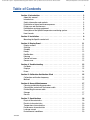
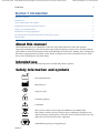
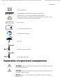
Check the 3M TM SpotOnTM Temperature Monitoring System website to ensure you have the most recent version of this document.
www.spotontemperature.com reorder #202305A
3
SpotOn™ Temperature Monitoring System
Model 370
Installation and Service Manual
Please forward to the
Biomedical Engineering
Department
3M SpotOn
™
™
Temperature Monitoring System
Check the 3M TM SpotOnTM Temperature Monitoring System website to ensure you have the most recent version of this document.
www.spotontemperature.com reorder #202305A
Revision History
Revision
Reason for Change
Pages Affected
Date
A
New Revision - First Release
All
March
2013
Check the 3M TM SpotOnTM Temperature Monitoring System website to ensure you have the most recent version of this document.
www.spotontemperature.com reorder #202305A
1
Table of Contents
Section 1: Introduction � � � � � � � � � � � � � � � � � � � � � �
About this manual � � � � � � � � � � � � � � � � � � � � � � �
Intended use � � � � � � � � � � � � � � � � � � � � � � � � � �
Safety information and symbols � � � � � � � � � � � � � � �
Explanation of signal word consequences � � � � � � � � � �
Proper use and maintenance � � � � � � � � � � � � � � � � �
Read before servicing equipment � � � � � � � � � � � � � � �
Description of the SpotOn temperature monitoring system
How it works � � � � � � � � � � � � � � � � � � � � � � � � � �
�
�
�
�
�
�
�
�
�
�
�
�
�
�
�
�
�
�
�
�
�
�
�
�
�
�
�
�
�
�
�
�
�
�
�
�
�
�
�
�
�
�
�
�
�
�
�
�
�
�
�
�
�
�
�
�
�
�
�
�
�
�
�
�
�
�
�
�
�
�
�
�
�
�
�
�
�
�
�
�
�
�
�
�
�
�
�
�
�
�
�
�
�
�
�
�
�
�
�
3
3
3
3
3
6
6
7
8
Section 2: Installation � � � � � � � � � � � � � � � � � � � � � � � � � � � � � � � � � 9
Mounting the SpotOn control unit� � � � � � � � � � � � � � � � � � � � � � � � � � 9
Section 3: Display Panel �
Display screens � � �
Start-up � � � � � � � � �
Standby � � � � � � � � �
Ready � � � � � � � � � �
Equilibration � � � � � � �
Running � � � � � � � � �
Control unit error � � � �
Sensor error � � � � � � �
�
�
�
�
�
�
�
�
�
�
�
�
�
�
�
�
�
�
�
�
�
�
�
�
�
�
�
�
�
�
�
�
�
�
�
�
�
�
�
�
�
�
�
�
�
�
�
�
�
�
�
�
�
�
�
�
�
�
�
�
�
�
�
�
�
�
�
�
�
�
�
�
�
�
�
�
�
�
�
�
�
�
�
�
�
�
�
�
�
�
�
�
�
�
�
�
�
�
�
�
�
�
�
�
�
�
�
�
�
�
�
�
�
�
�
�
�
�
�
�
�
�
�
�
�
�
�
�
�
�
�
�
�
�
�
�
�
�
�
�
�
�
�
�
�
�
�
�
�
�
�
�
�
�
�
�
�
�
�
�
�
�
�
�
�
�
�
�
�
�
�
�
�
�
�
�
�
�
�
�
�
�
�
�
�
�
�
�
�
�
�
�
�
�
�
�
�
�
�
�
�
�
�
�
�
�
�
�
�
�
�
�
�
�
�
�
�
�
�
�
�
�
�
�
�
�
�
�
�
�
�
�
�
�
�
�
�
�
�
�
�
�
�
�
�
�
�
�
�
�
�
�
�
�
�
�
�
�
�
�
�
�
�
�
�
�
�
�
�
11
� 11
� 11
� 11
� 12
� 12
� 12
� 12
� 12
Section 4: Troubleshooting �
On Mode � � � � � � � � � � �
Displays � � � � � � � � � � �
Errors � � � � � � � � � � � �
�
�
�
�
�
�
�
�
�
�
�
�
�
�
�
�
�
�
�
�
�
�
�
�
�
�
�
�
�
�
�
�
�
�
�
�
�
�
�
�
�
�
�
�
�
�
�
�
�
�
�
�
�
�
�
�
�
�
�
�
�
�
�
�
�
�
�
�
�
�
�
�
�
�
�
�
�
�
�
�
�
�
�
�
�
�
�
�
�
�
�
�
�
�
�
�
�
�
�
�
�
�
�
�
�
�
�
�
13
� � 13
� � 13
� � 14
Section 5: Calibration Verification Stick � � � � � � � � � � � � � � � � � � � � 15
Calibration verification frequency
� � � � � � � � � � � � � � � � � � � � � � 15
Method� � � � � � � � � � � � � � � � � � � � � � � � � � � � � � � � � � � � � � � � � 15
202305A
Section 6: General Maintenance � � � � � � �
Cleaning and disinfecting procedure � � � �
Cleaning the control unit and sensor cable
Disinfecting the sensor cable � � � � � � � �
Storage � � � � � � � � � � � � � � � � � � � �
Service� � � � � � � � � � � � � � � � � � � � �
�
�
�
�
�
�
�
�
�
�
�
�
�
�
�
�
�
�
�
�
�
�
�
�
�
�
�
�
�
�
�
�
�
�
�
�
�
�
�
�
�
�
�
�
�
�
�
�
�
�
�
�
�
�
�
�
�
�
�
�
�
�
�
�
�
�
�
�
�
�
�
�
�
�
�
�
�
�
�
�
�
�
�
�
�
�
�
�
�
�
�
�
�
�
�
�
�
�
�
�
�
�
�
�
�
�
�
�
�
�
�
�
�
�
�
�
�
�
�
�
17
17
17
17
17
17
Section 7: Specifications � � �
Physical characteristics � � �
Electrical characteristics� � �
Temperature characteristics�
Performance characteristics
Leakage current � � � � � � �
Environmental conditions � �
�
�
�
�
�
�
�
�
�
�
�
�
�
�
�
�
�
�
�
�
�
�
�
�
�
�
�
�
�
�
�
�
�
�
�
�
�
�
�
�
�
�
�
�
�
�
�
�
�
�
�
�
�
�
�
�
�
�
�
�
�
�
�
�
�
�
�
�
�
�
�
�
�
�
�
�
�
�
�
�
�
�
�
�
�
�
�
�
�
�
�
�
�
�
�
�
�
�
�
�
�
�
�
�
�
�
�
�
�
�
�
�
�
�
�
�
�
�
�
�
�
�
�
�
�
�
�
�
�
�
�
�
�
�
�
�
�
�
�
�
19
19
20
20
20
20
20
�
�
�
�
�
�
�
�
�
�
�
�
�
�
�
�
�
�
�
�
�
�
�
�
�
�
�
�
�
�
�
�
�
�
�
�
�
�
�
�
�
�
�
�
�
�
�
�
�
�
�
�
�
�
�
�
Check the 3M TM SpotOnTM Temperature Monitoring System website to ensure you have the most recent version of this document.
2
www.spotontemperature.com reorder #202305A
Check the 3M TM SpotOnTM Temperature Monitoring System website to ensure you have the most recent version of this document.
www.spotontemperature.com reorder #202305A
Introduction3
Section 1: Introduction
About this manual. . . . . . . . . . . . . . . . . . . . . . . . . . . . . . . . . . . . . . . . . . . . . . . . . . . . . . . . . . . . . . . . . . . . . . . . . . . . . . . . 3
Intended use. . . . . . . . . . . . . . . . . . . . . . . . . . . . . . . . . . . . . . . . . . . . . . . . . . . . . . . . . . . . . . . . . . . . . . . . . . . . . . . . . . . . . 3
Safety information and symbols.. . . . . . . . . . . . . . . . . . . . . . . . . . . . . . . . . . . . . . . . . . . . . . . . . . . . . . . . . . . . . . . . . . . 3
Explanation of signal word consequences. . . . . . . . . . . . . . . . . . . . . . . . . . . . . . . . . . . . . . . . . . . . . . . . . . . . . . . . . . . 4
Proper use and maintenance. . . . . . . . . . . . . . . . . . . . . . . . . . . . . . . . . . . . . . . . . . . . . . . . . . . . . . . . . . . . . . . . . . . . . . . 6
Read before servicing equipment. . . . . . . . . . . . . . . . . . . . . . . . . . . . . . . . . . . . . . . . . . . . . . . . . . . . . . . . . . . . . . . . . . . 6
Description of the SpotOn temperature monitoring system.. . . . . . . . . . . . . . . . . . . . . . . . . . . . . . . . . . . . . . . . . . 7
How it works. . . . . . . . . . . . . . . . . . . . . . . . . . . . . . . . . . . . . . . . . . . . . . . . . . . . . . . . . . . . . . . . . . . . . . . . . . . . . . . . . . . . . 8
About this manual
This Installation and Service Manual describes the setup and maintenance of the 3M™ SpotOn™
temperature monitoring system. The SpotOn temperature monitoring system is to be used by healthcare
professionals in clinical environments only. Read and follow all instructions, labeling and accompanying
documents supplied with the SpotOn system. Failure to follow instructions could lead to misuse of the
device, device malfunction, or patient injury.
Intended use
Measure, monitor, and trend body temperature of adult and pediatric patients.
Safety information and symbols
Date of manufacture
Manufacturer
Single use only
Container quantity
CAUTION
This system is subject to the European WEEE Directive 2002/96/EC.
This product contains electrical and electronic components and must not be
disposed of using standard refuse collection. Please consult local directives for
disposal of electrical and electronic equipment.
202305A
Defibrillation-proof type CF applied part
Check the 3M TM SpotOnTM Temperature Monitoring System website to ensure you have the most recent version of this document.
www.spotontemperature.com reorder #202305A
4Introduction
Class II equipment
Authorized Representative in the European Community
CAUTION: Recycle to avoid environmental contamination
This product contains recyclable parts. For information on recycling - please
contact your nearest 3M Service Center for advice.
See accompanying documents
Consult operator’s manual
Direct current
Keep dry
Hardware temperature limits
Sensor temperature limits
Explanation of signal word consequences
ARNING: Indicates a hazardous situation which, if not avoided, could result
W
in death or serious injury.
AUTION: Indicates a hazardous situation which, if not avoided, could result
C
in minor or moderate injury.
NOTICE: Indicates a situation which, if not avoided, could result in property
damage only.
Check the 3M TM SpotOnTM Temperature Monitoring System website to ensure you have the most recent version of this document.
www.spotontemperature.com reorder #202305A
Introduction5
WARNINGS
1. To reduce the risks associated with access to critical patient information or equipment:
• The SpotOn control unit is to be attached to other equipment by authorized service
personnel only.
• Do not re-install or re-locate the SpotOn control unit.
2. To reduce the risks associated with hazardous voltage, fire, and thermal energy hazards:
• Use ONLY with 3M SpotOn system components (sensors, cables, and power supply). Do
not substitute other devices for the SpotOn control unit, sensor, cables, or power supply.
• Do not use the SpotOn temperature monitoring system (sensor, control unit, cables, or
cords) in an MRI environment.
3. To reduce the risks associated with hazardous voltage and fire:
• Keep power supply visible and accessible at all times. The plug on the power supply serves
as the disconnect device. The power outlet shall be as close as practical and shall be easily
accessible.
• Use only the power supply specified for this product and certified for the country of use.
• Use only a properly grounded power outlet; do not use extension cords or multiple
portable socket outlets.
• Do not allow the power supply to get wet.
• Do not use the SpotOn control unit when it appears the unit or system components are
damaged. Contact 3M Patient Warming technical support at 1-800-733-7775 or 952-9471200.
• Do not service or modify the power supply, control unit, cables, sensor, or any part of the
3M SpotOn system. There are no user serviceable parts.
4. To reduce the risks associated with fire:
• This system is not suitable for use in the presence of a flammable anesthetic mixture with
air nitrous oxide.
5. To reduce the risks associate with pressure, and crushed or entangled cords and connectors:
• Do not allow the patient to lie on any SpotOn sensor cable or connector.
• Always position cables and cords away from the patient’s body.
• Do not use a headband or other device to secure the SpotOn sensor to the patient.
6. To reduce the risks associated with incorrect system or sensor use:
• Limit use of the SpotOn temperature sensor to 24 hours. Extended use may compromise
skin, cause degradation of material or performance.
• Avoid exposing the SpotOn temperature sensor, sensor cable, power supply, and control
unit to surgical skin surface preparation solutions or other fluids.
• Use an additional independent thermometer to measure body temperature during
intentional hyperthermia or hypothermia therapy.
• Confirm unanticipated temperature reading with an independent thermometer, if needed.
• Do not reposition the SpotOn temperature sensor; repositioning may weaken the sensor
adhesive, damage the sensor, or compromise the device performance.
• Avoid placing the sensor in the center of the forehead as this may affect sensor accuracy.
7. To reduce the risks associated with exposure to biohazards:
• Follow facilities policies and procedures for disposal of contaminated materials.
• Always perform the decontamination procedure prior to returning the SpotOn
temperature monitoring system for service and prior to disposal.
8. To reduce the risks associated with entanglement:
• Do not leave pediatric patients unattended while using the SpotOn temperature
monitoring system.
202305A
Check the 3M TM SpotOnTM Temperature Monitoring System website to ensure you have the most recent version of this document.
www.spotontemperature.com reorder #202305A
6Introduction
CAUTIONS
1.
To reduce the risks associated with skin maceration:
2.
• Do not use the sensor on damaged or compromised skin.
To reduce the risks associated with cross-contamination:
3.
• Clean the sensor cable before connecting to a new sensor.
To reduce the risks associated with impact and facility medical device damage:
4.
• Do not use the SpotOn control unit as a handle to transport or to move the device to
which it is attached.
• Do not initiate temperature monitoring unless the SpotOn control unit is safely placed
on a hard, flat surface or is securely mounted.
To reduce the risks associated with environmental contamination:
• Follow applicable regulations when disposing of this device or any of its electronic
components.
NOTICES
1. The SpotOn temperature monitoring system meets medical electronic interference
requirements. If radio frequency interference with other equipment should occur, connect the
unit to a different power source.
2. Federal law (USA) restricts this device to sale by or on the order of a licensed healthcare
professional.
3. To avoid SpotOn temperature monitoring system damage that may impact performance:
• Do not store the SpotOn control unit and system components in a wet or damp place.
• Do not spray cleaning solutions onto the control unit or into the sensor cable connector.
• Do not immerse the SpotOn temperature monitoring control unit or system components
in any liquid or subject them to any sterilization process.
• Do not use solvents such as acetone or thinner to clean the control unit; avoid abrasive
cleaners.
• Clean control unit exterior with a damp soft cloth and 70% mixture of isopropyl alcohol
and water. For full cleaning procedures see “Section 5: General Maintenance” on page 21.
• Do not immerse any of the devices or use a dripping wet cloth for cleaning.
4. The SpotOn temperature monitoring sensor is not made with natural latex material.
5. To the full extent permitted by law, the manufacturer and/or importer declines all
responsibility for injury resulting from the unit being used in conjunction with unapproved
system components.
Proper use and maintenance
Arizant Healthcare Inc., a 3M company assumes no responsibility for the reliability, performance, or
safety of the temperature monitoring system if the following events occur:
• Modifications or repairs are performed by unqualified personnel.
• The unit is used in a manner other than that described in the Operator’s Manual.
• The unit is installed in an environment that does not meet the appropriate electrical requirements.
Read before servicing equipment
• All repair, calibration, and servicing of this equipment must be performed by 3M Patient
Warming.
• There are no user serviceable parts inside the equipment or power supply.
Check the 3M TM SpotOnTM Temperature Monitoring System website to ensure you have the most recent version of this document.
www.spotontemperature.com reorder #202305A
Introduction7
Description of the SpotOn temperature
monitoring system
The SpotOn temperature monitoring system measures the core temperature of the patient. The system
is comprised of the SpotOn temperature sensor, which connects to the SpotOn control unit through the
sensor cable, a power supply, and an optional monitor cable. For additional sensors, sensor cable, power
supply, control unit stand, monitor cable, hook-and-loop, or foam adhesive, contact 3M Patient Warming.
Monitor Cable
Power Supply
Sensor Cable
PAT I
OR
3M™ SpotOn™
Control Unit
N
ENT SE
S
Temperature Sensor
Sensor Connector
Figure 1-1: SpotOn Temperature Monitoring System
202305A
Check the 3M TM SpotOnTM Temperature Monitoring System website to ensure you have the most recent version of this document.
www.spotontemperature.com reorder #202305A
8Introduction
How it works
The SpotOn temperature monitoring system uses zero-heat-flux thermometry to accurately measure a person’s
core temperature as characterized in Figure 1-2 below. 1) The SpotOn temperature monitoring system gently
warms the sensor creating an isothermal pathway under the sensor. 2) Once equilibrated to the core temperature,
skin-surface heat loss to the environment is prevented and a zero-heat-flux condition is established. 3) When the
temperature sensor reaches equilibrium with the patient’s core temperature, the SpotOn control unit displays an
accurate, noninvasive measurement of the patient’s core temperature.
Temperature
Sensor
Skin
Surface
Deep Tissue
1) Placement and connection
2) Equilibration - isothermal pathway development
3) Equilibrated - isothermal pathway established
Figure 1-2: Isothermal pathway formation with zero-heat-flux technology
SpotOn control unit
The SpotOn control unit displays non-invasive core temperature measurements obtained from the SpotOn
temperature sensor. The current temperature is displayed numerically, and previous temperature data is displayed
graphically as a temperature trend graph. When the sensor is plugged into the sensor cable and equilibration is
complete, the control unit reads up to the last two hours of stored temperature data and displays the temperature
trend graph. Disconnections of the sensor from the sensor cable are indicated by gaps in the temperature trend
graph. The current temperature measurement can be continuously transmitted to a patient vital signs monitor
through the optional SpotOn monitor cable using a standard YSI-400 type input.
SpotOn temperature sensor
The SpotOn sensor is constructed of two layers of medical grade foam and a flexible circuit which contains a
resistive warming circuit, two calibrated thermistors, and nonvolatile memory. The information that generates
the temperature trend graph is stored on the SpotOn sensor. When the patient is transferred from one location
to another, the SpotOn sensor is disconnected from the SpotOn sensor cable so the sensor is left in place on the
patient. The SpotOn sensor may be reconnected to a different SpotOn sensor cable and control unit when the
patient arrives at the next point of care. Once the SpotOn sensor is reconnected to the SpotOn sensor cable, the
system will begin to reequilibrate and will regenerate the stored temperature trend graph and display the patient’s
current temperature. The act of disconnecting and reconnecting the SpotOn sensor from the sensor cable is
indicated by a gap in the temperature trend graph.
Check the 3M TM SpotOnTM Temperature Monitoring System website to ensure you have the most recent version of this document.
www.spotontemperature.com reorder #202305A
Installation9
Section 2: Installation
WARNING:
1. To reduce the risks associated with access to critical patient information or equipment do not
mount the control unit:
•
•
•
•
To a surface that is not flat or clean.
Over air vents of other equipment.
Over controls, displays, or buttons of other equipment.
Over speakers or alarms of other equipment.
Mounting the SpotOn control unit
CAUTION:
To prevent injury, mount the SpotOn temperature monitoring system at a height no higher than 84”
(213 cm).
1. Use the provided hook-and-loop or foam adhesive to secure the control unit stand to any hard,
flat surface (use only the 3M provided/specified control unit mounting materials).
Note:
Confirm the hook-and-loop is securely fastened together before mounting the control unit to a surface.
Recommend: Clean surface with a 70% mixture of isopropyl alcohol and water prior to applying the
provided hook-and-loop or foam adhesive.
2. The SpotOn control unit’s height and orientation can be adjusted by loosening/tightening the
control unit stand knob on the back of the unit.
Figure 2-1: Control Unit Mounting Configuration
202305A
Check the 3M TM SpotOnTM Temperature Monitoring System website to ensure you have the most recent version of this document.
10
www.spotontemperature.com reorder #202305A
Check the 3M TM SpotOnTM Temperature Monitoring System website to ensure you have the most recent version of this document.
www.spotontemperature.com reorder #202305A
Display Panel
11
Section 3: Display Panel
Display screens
Start-up
The start-up screen displays for approximately five
seconds when the control unit is initially powered ON.
The revision number of the control unit software is
also displayed.
FW-x.x.xxx
Standby
The SpotOn system graphic is displayed when the unit
is not in use.
3M SpotOn
™
™
Temperature Monitoring System
202305A
Check the 3M TM SpotOnTM Temperature Monitoring System website to ensure you have the most recent version of this document.
www.spotontemperature.com reorder #202305A
12
Display Panel
Ready
The ready screen displays the serial number of the
SpotOn sensor and indicates the SpotOn sensor
cable and sensor are properly attached to the SpotOn
control unit. The SpotOn sensor is now ready to be
attached to the patient.
SN - 000000000
Equilibration
A flashing yellow temperature display indicates the
sensor has been connected to the patient and to the
control unit and is in the process of equilibration.
The graph below the temperature output indicates
the progress of equilibration. This process will take
approximately three minutes.
If you see a temperature in the upper left hand corner
of the screen, that is the last recorded temperature that
has been captured by the sensor. The sensor captures
and records a temperature every five minutes.
36 9
39
37
35
C
36 0
After the equilibration is complete, the core
temperature of the patient is displayed on the SpotOn
control unit in bold white numbers and can be
automatically transmitted to the patient monitor via
the monitor cable.
Running
The running screen displays the core temperature of
the patient in white. The trend graph at the bottom
of the screen displays up to the last two hours of the
patient’s temperature in five minute increments. The
bars on the graph will begin filling from the right with
the 36°C always visible. The blue bars indicate that the
temperature dropped below 36°C (white indicates the
temperature is above 36°C).
Control unit error
The SpotOn control unit error screen displays when
there is a system error. Discontinue use of unit.
Contact a biomedical technician.
E-xx
Sensor error
The sensor error screen displays when there is a
temperature sensor or cable error. See “Section 4:
Troubleshooting” on page 13 for details.
E-xx
C
Check the 3M TM SpotOnTM Temperature Monitoring System website to ensure you have the most recent version of this document.
www.spotontemperature.com reorder #202305A
Troubleshooting13
Section 4: Troubleshooting
The following conditions are listed in the order of which troubleshooting actions should be performed.
On Mode
Condition
Cause
Unit does not power up.
Unit is not plugged in, or power supply Make sure the power supply is plugged
is not plugged into an appropriate
into the control unit. Make sure
outlet.
the control unit is plugged into an
appropriate power outlet.
Action
Unit failure.
Contact 3M Patient Warming
technical service.
Cause
Action
Displays
Condition
“Ready” screen continues to display
Sensor not properly adhered to the
while sensor is adhered to the patient. patient.
SN - 000000000
Make sure the sensor is connected to
the patient.
Low patient temperature
(below 29°C).
Press and hold the °C/°F button on
the back of the control unit for five
seconds to force the control unit into
equilibration mode. The patient’s
temperature will then display.
Control unit failure.
Discontinue use of unit. Contact 3M
Patient Warming technical service.
“Running” screen does not appear on Control unit may still be equilibrating. Wait until the SpotOn control unit has
the control unit.
finished equilibration. Continue use.
Control unit failure.
Contact 3M Patient Warming
technical service.
Patient temperature does not appear
on the patient monitor.
Control unit may still be equilibrating. Wait until the SpotOn control unit has
finished equilibration. Continue use.
36 9
Monitor cable is not plugged in.
Make sure the monitor cable is
plugged into the control unit and
patient monitor.
Cable failure.
• Replace monitor cable.
• Contact 3M Patient Warming
technical service.
Control unit failure.
Contact 3M Patient Warming
technical service after use.
Cable failure.
• Confirm SpotOn monitor cable is
being used.
• Replace monitor cable.
• Check resistance of cable.
• Contact 3M Patient Warming
technical service.
C
39
37
35
36 0
C
The patient’s temperature output on
the control unit and patient monitor
does not read the same value.
202305A
Check the 3M TM SpotOnTM Temperature Monitoring System website to ensure you have the most recent version of this document.
www.spotontemperature.com reorder #202305A
14Troubleshooting
Errors
Error Screen
Condition
Cause
Action
E-1 through E-99
Sensor not properly
connected to the sensor
cable.
Make sure the sensor is connected to
the sensor cable, by disconnecting and
reconnecting the sensor.
Sensor failure.
Replace sensor.
Cable failure.
• Replace sensor cable.
• Contact 3M Patient Warming
technical service.
Control unit failure.
• Disconnect the unit from power
source.
• Allow 30-60 seconds for the unit
to reset.
• Reconnect the unit to the power
source to determine if the unit reset
or if it is a permanent error.
E-xx
E-100 and up
E-xx
Discontinue use of the unit. Contact a
biomedical technician.
Check the 3M TM SpotOnTM Temperature Monitoring System website to ensure you have the most recent version of this document.
www.spotontemperature.com reorder #202305A
Calibration Verification Stick
15
Section 5: Calibration Verification Stick
Calibration verification frequency
Every 12 months or according to institutional protocol.
Tools and equipment
• Calibrated digital multi-meter
• Model 90111 Calibration verification stick
Method
1. Connect the power supply to the back of the SpotOn control unit (see Figure 5-1: Back of
Control Unit).
Plug the power supply into an appropriate outlet. The standby screen will illuminate.
2. Connect the SpotOn sensor cable to the front of the control unit (see Figure 5-2: Front of
Control Unit).
Stand Knob
Digital Port
(used by 3M personnel only)
°C/°F Temperature
Display Button
Monitor Cable Port
Power Input Port
Figure 5-1: Back of Control Unit
Figure 5-2: Front of Control Unit
202305A
Check the 3M TM SpotOnTM Temperature Monitoring System website to ensure you have the most recent version of this document.
16
www.spotontemperature.com reorder #202305A
Calibration Verification Stick
3. Connect the SpotOn calibration verification stick to the sensor cable. Ensure the verification stick is
fully inserted into the sensor cable.
4. The screen shows the actual calibrated thermistor readings for the skin and heater thermistors.
The calibration verification stick contains a precision resistor for each calibrated thermistor with
a known reference value corresponding to a reference temperature. Verify that the reference
temperature for each calibrated thermistor matches the displayed value (36.0 ± 0.1°C, 96 .8± 0.2°F)
5. If the reference temperatures are within acceptable limits, continue with steps below.
If the reference temperatures are outside of the acceptable limits, discontinue use of the SpotOn
temperature monitoring system. Contact 3M patient warming technical service at 1-800-733-7775.
Figure 5-3: Calibration screens (Celsius and Fahrenheit)
6. Plug the monitor cable to the monitor port on the back of the control unit.
7. Wait for the control unit to calibrate and start emulating data. The internal relay will “click” and the
display will refresh when the emulation is active.
8. Set the multi-meter to the 2000 ohm range.
Note: Zero the multi-meter as necessary for all resistance measurements.
9. Hold the digital multi-meter leads to the tip and the ring on the end of the monitor cable.
10. Confirm the reading on the multi-meter is 1412 ohms +/—15 ohms.
11. If the reading on the multi-meter is within acceptable limits, return the SpotOn temperature
monitoring system to use.
If the reference reading on the multi-meter is outside of the acceptable limits, discontinue use of the SpotOn temperature monitoring system. Contact 3M patient warming technical service at 1-800-
733-7775.
Check the 3M TM SpotOnTM Temperature Monitoring System website to ensure you have the most recent version of this document.
www.spotontemperature.com reorder #202305A
General Maintenance
17
Section 6: General Maintenance
Cleaning and disinfecting procedure
CAUTION:
• Do not immerse any of the devices or use a dripping wet cloth for cleaning. Moisture
may seep inside the device and damage the electrical components and lead to incorrect
temperature reporting.
• Do not spray cleaning solutions onto the control unit or into the sensor cable connector.
Damage to the control unit or sensor cable connector may occur.
Cleaning the control unit and sensor cable
Clean the SpotOn control unit on an as-needed basis or per facility policies and procedures for
cleaning electronic equipment. Clean the sensor cable between each use.
1. Disconnect power supply from power outlet.
2. Use a slightly damp soft cloth moistened with a mild, nonabrasive cleaning solution to clean the
device surfaces, cords, and cables. Avoid getting liquid into electronic ports.
3. Dry with a separate soft cloth.
Disinfecting the sensor cable
1. Clean the devices as described above.
2. Wipe down the control unit and cable using a damp soft cloth and 70% isopropyl alcohol
solution. Avoid getting liquid into electronic ports.
3. Dry with a separate soft cloth.
Storage
Notice: Do not store the SpotOn control unit and system components in a wet or damp place. Damage
to the electrical components may occur.
Store all SpotOn components at room temperature and in a dry place when not in use.
Service
All service must be performed by 3M Patient Warming or an authorized service technician. Call 3M
Patient Warming Customer Service at 1-800-733-7775 for service information..
202305A
Check the 3M TM SpotOnTM Temperature Monitoring System website to ensure you have the most recent version of this document.
18
www.spotontemperature.com reorder #202305A
Check the 3M TM SpotOnTM Temperature Monitoring System website to ensure you have the most recent version of this document.
www.spotontemperature.com reorder #202305A
Specifications19
Section 7: Specifications
Physical characteristics
Dimensions of Control Unit
9.3 cm (3.7 in) high, extendable to 11.4 cm (4.5 in) high
7.1 cm (2.8 in) wide, 4.3 cm (1.7 in) deep
Weight of Control Unit
128 g (4.5 oz)
Dimensions of Sensor
4.1 cm (1.6 in) diameter, 0.5 cm (0.2 in) thick
Length of the Sensor Cable
400 cm (158 in)
Classification
MEDICAL - GENERAL MEDICAL EQUIPMENT AS TO ELECTRICAL SHOCK, FIRE
AND MECHANICAL HAZARDS ONLY IN ACCORDANCE WITH UL 60601-1; CAN/
CSA-C22.2, No. 60601-1; ANSI/AAMI ES60601-1:2005 CSA-C22.2 No. 601-1:08; Control
No. 4HZ8. No.4HZ8
Classified under IEC 60601-1 Guidelines (and other national versions of the Guidelines) as Class II,
Type CF, Defibrillation-Proof, Ordinary Equipment. Conforms to EN12470. Not suitable for use in the
presence of flammable anesthetic mixtures with air or nitrous oxide.
Classified by Underwriters Laboratories Inc. with respect to electric shock, fire, and mechanical hazards
only, in accordance with UL 60601-1, IEC 60601-1, and Canadian/CSA C22.2 No. 601.1. ANSI/AAMI ES
60601-1; 2005.Classified under the Medical Device Directive as a Class IIb device.
Accuracy
25°C to 43°C ± 0.2°C
Sensor Material
Medical grade foam and adhesive
PET flexible circuit
Recommended Calibration Check
Every 12 months or according to institutional protocol.
Sensor Shelf Life
36 months
Digital Port (used by 3M personnel only)
Serial output 0 [-12 to + 12]
Monitor Cable Port
Provides a resistance that corresponds to a YSI-400 thermistor at the displayed temperature. It is
electrically isolated from the SpotOn control unit.
202305A
Check the 3M TM SpotOnTM Temperature Monitoring System website to ensure you have the most recent version of this document.
www.spotontemperature.com reorder #202305A
20Specifications
Electrical
characteristics
Environmental
conditions
External power supply
Ambient temperature range
100-240 VAC, 50-60 Hz
Output; 5 VDC
Class II, double insulated medical grade
Maximum heating power
2W
Temperature
characteristics
Over-temperature cutoff
43°C - Skin thermistor reading
44.5°C - Heater thermistor reading
Performance
characteristics
Equilibration time
Approximately three minutes
Time response
Approximately three minutes
Measurement locations
Patient’s lateral forehead above the orbital
ridge
Measurement range
25°C - 43°C
Measurement readout
Celsius or Fahrenheit
Leakage current
CF classification. Meets leakage current
requirements in accordance with UL 60601-1
and IEC 60601-1.
10°C to 40°C (50°F to 104°F)
Storage and transport temperature
range
-20°C to 60°C (-4°F to 140°F)
Store all components at room temperature
and in a dry place when not in use.
Operating humidity
10 to 75% RH, noncondensing
Atmospheric pressure range
80 kPa to 106 kPa (12 PSI to 15 PSI)
Oxygen environment
The sensor only is suitable for use in the
presence of an oxygen enriched environment.
Check the 3M TM SpotOnTM Temperature Monitoring System website to ensure you have the most recent version of this document.
Calibration Verification Log
Date
Action Performed
Calibration check reference temperatures
Cable monitor resistance
Calibration check reference temperatures
Cable monitor resistance
Calibration check reference temperatures
Cable monitor resistance
Calibration check reference temperatures
Cable monitor resistance
Calibration check reference temperatures
Cable monitor resistance
Calibration check reference temperatures
Cable monitor resistance
Calibration check reference temperatures
Cable monitor resistance
Calibration check reference temperatures
Cable monitor resistance
www.spotontemperature.com reorder #202305A
Made in the USA by 3M Health Care.
3M is a trademark of 3M Company, used under license in Canada. SPOTON is a trademark of Arizant Healthcare Inc., used under
license in Canada. ©2013 Arizant Healthcare Inc. All rights reserved.
3M Deutschland GmbH, Health Care Business
Carl-Schurz-Str. 1, 41453 Neuss, Germany
3M Health Care, 2510 Conway Ave., St. Paul, MN 55144 USA
TEL 800-228-3957 | www.spotontemperature.com
202305A 05/13