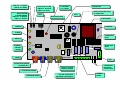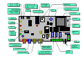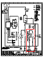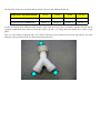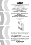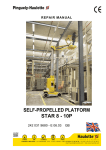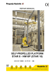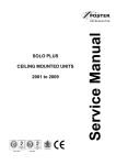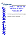
1
SCOTSMAN EUROPE SERVICE DEPARTMENT
SP-08.01 – FEBR. ‘08
MC 1210 AT 230/60/3
NEW COPELAND
COMPRESSOR
Starting from MC 1210 s.n. 3666 the previous Tecumseh Europe compressor operating
at 230V 50-60Hz 3Ph has been replaced with a new Copeland one that operate ONLY
at 230V 60Hz 3Ph.
The Part Nbr of this new compressor is 18008749 24 and it's exchangeable with the
former one making some modification on the refrigerant tubes.
SCOTSMAN EUROPE SERVICE DEPARTMENT
SP-08.02 – FEBR. ‘08
MV SERIES
CHANGES IN PC BOARD
SOFTWARE
Starting from end of 2007, the Software of the PC Board used in all MV units has been
modified on the operation of the AUTORESET Jumper/Contacts.
Rather then move automatically the machine in Auto-Reset Mode, when the
AUTORESET contacts are open (see photo below)
the new software is keeping a constant level of the water into the water reservoir during
the entire freezing cycle by energizing the water inlet solenoid valve once the water
level drops down from the two metal plates of the water level sensor.
This modification has been required for the machines installed on board of the vessels in
order to assure water all the time into the water reservoir (at lower level compare with
the standard machines) during the freezing cycle.
In case the MV PC Board Part Nbr CM 33580150 is installed in a standard machine
W/OUT the Jumper on the Auto-Reset contacts, the machine is constantly asking for
water during the freezing cycle.
If so, to solve the problem, just Jump IN the two contacts in Manual-Reset mode to
have the water level sensor energizing the water inlet solenoid valve just at the
beginning of the freezing cycle.
SCOTSMAN EUROPE SERVICE DEPARTMENT
SP-08.03 – FEBR. ‘08
AC 46 - AC 56 - AC 86 -AC 106
N EW MA S TER A N D
ALARM/RE-SET SWITCHES
Starting from the following serial nbrs:
AC 46 S.N.
AC 56
AC 86
AC 106
4743
1860
1968
1552
the Green Master Lighted Switch as well as the Red Alarm/Re-Set Switch have been
changed again going back to the original solution/application used on the AC..6 series
manufactured till mid 2007.
The new Switches are available under the same part nbrs of the first ones i.e.:
Green Master Lighted Switch
Red Alarm/Re-Set Switch
P/N
620487 00
620487 01
These new Switches are a little bit different in size (19,6 mm wide, at plastic clips
location, rather then 19,4 mm) of the former one as well as in their contacts/spade
connectors identification numbers.
Attached the wiring diagram showing the electrical connections of the two Lighted
Switches with the references of the electrical contacts of the old ones (inside the
brackets) and new/current ones (with no brackets).
Anyway, as in the new switches the contact numbers are not very easily readable we
suggest you to look all the time to the small pin (see on the circle of the bottom photo)
anytime it's needed to replace it.
The same are also shown on the drawings attached.
The Switches used on AC..6 Series manufactured from mid 2007 up to now, will be kept available as spare parts under
the following part nbrs:
Green Master Lighted Switch
Re-Set Switch
Red Warning Light
P/N
620487 02
620487 03
620504 00
OLD VERSION
BROWN
BROWN
BLACK
1
2
4
5
BLUE
1
2
4
5
BLUE
RED
WHITE
NEW VERSION
BROWN
BROWN
RED
C1
2A
4B
1A
2A
3B
BLUE
4B
BLUE
WHITE
C1
1A
3B
BLACK
SCOTSMAN EUROPE SERVICE DEPARTMENT
SP-08.04 – MARCH ‘08
TC 180
NEW WATER TRAY DRAIN
FILTER
Starting from last month we have changed the drain filter of the water drip tray moving
from the standard one used in all storage bin to a version with a central hole for easy
cleaning of the inside of the water drain/waste hoses as shown on the here below photo.
This drain filter with central hole is available under Part Nbr 660211 03 and can be used
in place of the old one.
SCOTSMAN EUROPE SERVICE DEPARTMENT
SP-08.05 – MARCH ‘08
ACC COMPRESSORS
N E W T E R M I N A L B OA R D
Recently we have received from our compressor supplier ACC (former name Cubigel)
compressors equipped with a new electrical control box.
To help you in its electrical connections, mainly when new compressor is used in place
of a old version one, we are sending here below a photo showing the power connectionS
so to avoid any possible confusion at time of installation.
LINE
EARTH
GROUND
NEUTRAL
SCOTSMAN EUROPE SERVICE DEPARTMENT
SP-08.06 – MARCH ‘08
AF/MF SERIES
COUPLING LUBRICATION
We would like to remind you that it's very important to provide correct/proper
lubrication of the inside bore of the upper semi-coupling as well as to the external
surfaces of the teeth as shown on the here below photo.
The correct lubrication allows the upper semi-coupling to move it down, by the load of
the upper spring, in case of any rising up during its rotation.
GREASE
SCOTSMAN EUROPE SERVICE DEPARTMENT
SP-08.07 – MARCH ‘08
MC 8 AS/WS
N E W M OD E L
A new Modular Cuber is now available for the market.
It's mainly based on the same refrigerant, water and electrical system of the model AC
206 but w/out the storage bin.
About PC Board, this new model is equipped with a new generation of PC Board,
already tested in the field on more then one hundred machines.
This new PC Board, available under Part Nbr 620462 06 consists of the standard PC
Board used till new with the integration of the Cleaning Reminder Board.
Moreover the compressor relay installed in this PC Board can load up to 16 amps
current enabling the direct connection of the compressor to the PC Board.
Attached you can find the schematic diagram of this new PC Board of both our two PC
Board suppliers (Syen & Pro.El.Ind.) where it's also possible to connect directly the
water reservoir level sensor (Red Sensor Socket) of the machines equipped with water
pump discharge system (EC Series).
Setting of the Dip Switches for Medium Size Cube is:
MCM 8 A
MCM 8 W
1
ON
ON
2
OFF
OFF
3
ON
ON
4
ON
ON
5
ON
ON
6
OFF
OFF
7
ON
ON
8
ON
ON
9
ON
ON
10
ON
OFF
This new PC Board is no longer equipped with the I/R Trimmer as the calibration of the
Optical Ice Level Control can be done directly with the PC Board as per here below
procedure:
•
•
•
•
•
•
•
Be sure that both Transmitter & Receiver of the Ice Level Control are properly
clean and scale free
Switch OFF the machine at Green Master Push Button Switch
Push and Hold the PC Board Push Button
Switch ON the machine at Green Master Push Button Switch
Wait few seconds till the PC Board Leds flash once
Release the PC Board Push Button
Calibration is done
This operation can be done anytime is needed and MUST be done when a new PC Board or a new Optical Ice Level
Control is installed/replaced in the machine.
This new PC Board is also set up to Switch OFF the machine at Bin Full ONLY at the end of the Harvest/Defrost
cycle enabling the machine to discharge ONLY full size cubes and have the water system already filled up with water
for new freezing cycle.
Attached please find the instruction for the removal of the Optical Ice Level Control (in case it's needed) from its
inside transport location.
The MC 8 Service Manual will be available shortly in internet at our web site www.scotsman-ice.it
JUMP OUT - EC SERIES
JUMP OUT - EC SERIES
JUMP IN - AC SERIES
JUMP IN - AC SERIES
WATER SYSTEM
WATER SYSTEM
CLEANING REMIND
CLEANING REMIND
JUMP OUT - 12 MONTHS
JUMP OUT - 12 MONTHS
JUMP IN - 6 MONTHS
JUMP IN - 6 MONTHS
START UPDELAY TIME
START UPDELAY TIME
JUMP OUT - NO DELAY
JUMP OUT - NO DELAY
JUMP IN - 60’ DELAY
JUMP IN - 60’ DELAY
TEST
TEST
0°C-BLINKING
0°C-BLINKING
-13°C-STEADY
-13°C-STEADY
MICROPROCESSOR
MICROPROCESSOR
PUSH BUTTON
PUSH BUTTON
TRIAC
TRIAC
WATER DRAIN PUMP RELAY
WATER DRAIN PUMP RELAY
EC SERIES ONLY
EC SERIES ONLY
TRANSFORMER
TRANSFORMER
FREEZING
FREEZING
VARISTOR
VARISTOR
ALARM
ALARM
COMPRESSOR
COMPRESSOR
RELAY
RELAY
BIN FULL
BIN FULL
WATER PUMP
WATER PUMP
RELAY
RELAY
EXTERNAL
EXTERNAL
SWICHES
SWICHES
SOCKET
SOCKET
POWER
POWER
SYEN
FUSE
FUSE
WATER LEVEL SENSOR
WATER LEVEL SENSOR
EC SERIES ONLY
EC SERIES ONLY
EVAPORATOR SENSOR
EVAPORATOR SENSOR
CONDENSER SENSOR
CONDENSER SENSOR
OPTICAL ICE LEVEL
OPTICAL ICE LEVEL
CONTROL SENSOR
CONTROL SENSOR
HOT GAS, WATER INLET
HOT GAS, WATER INLET
AND PURGE VALVES RELAY
AND PURGE VALVES RELAY
COMPRESSOR
COMPRESSOR
ELECTRICAL
ELECTRICAL
CONNECTIONS
CONNECTIONS
TERMINAL
TERMINAL
BOARD
BOARD
JUMP OUT - EC SERIES
JUMP OUT - EC SERIES
JUMP IN - AC SERIES
JUMP IN - AC SERIES
WATER SYSTEM
WATER SYSTEM
CLEANING REMIND
CLEANING REMIND
JUMP OUT - 12 MONTHS
JUMP OUT - 12 MONTHS
JUMP IN - 6 MONTHS
JUMP IN - 6 MONTHS
START UPDELAY TIME
START UPDELAY TIME
JUMP OUT - NO DELAY
JUMP OUT - NO DELAY
JUMP IN - 60’ DELAY
JUMP IN - 60’ DELAY
TEST
TEST
0°C-BLINKING
0°C-BLINKING
-13°C-STEADY
-13°C-STEADY
PUSH BUTTON
PUSH BUTTON
TRIAC
TRIAC
MICROPROCESSOR
MICROPROCESSOR
WATER DRAIN PUMP RELAY
WATER DRAIN PUMP RELAY
EC SERIES ONLY
EC SERIES ONLY
TRANSFORMER
TRANSFORMER
FREEZING
FREEZING
VARISTOR
VARISTOR
ALARM
ALARM
COMPRESSOR
COMPRESSOR
RELAY
RELAY
BIN FULL
BIN FULL
WATER PUMP
WATER PUMP
RELAY
RELAY
EXTERNAL
EXTERNAL
SWICHES
SWICHES
SOCKET
SOCKET
POWER
POWER
PRO.EL.IND.
FUSE
FUSE
WATER LEVEL SENSOR
WATER LEVEL SENSOR
EC SERIES ONLY
EC SERIES ONLY
EVAPORATOR SENSOR
EVAPORATOR SENSOR
CONDENSER SENSOR
CONDENSER SENSOR
OPTICAL ICE LEVEL
OPTICAL ICE LEVEL
CONTROL SENSOR
CONTROL SENSOR
HOT GAS, WATER INLET
HOT GAS, WATER INLET
AND PURGE VALVES RELAY
AND PURGE VALVES RELAY
COMPRESSOR
COMPRESSOR
ELECTRICAL
ELECTRICAL
CONNECTIONS
CONNECTIONS
TERMINAL
TERMINAL
BOARD
BOARD
MC 8 AS/WS
ICE LEVEL OPTICAL CONTROL INSTALLATION
1. Remove screw and ice chute frame.
3. Cut plastic strap and release ice level
control. from its holding bracket.
2. Take ice chute frame out from side
panel opening area.
4. Install the cable protection grommet
6. Check for proper installation (not too
bend or pinched)
5. Fit in cable with its protection grommet
in suitable hole …..
7. Install again ice chute frame ….
…..available on the ice chute opening
perimeter area
….and secure it with former removed
screws
SCOTSMAN EUROPE SERVICE DEPARTMENT
SP-08.08 – MARCH ‘08
AC 176 & AC 226 AS/WS
NEW PC BAORD
On the following serial numbers of models AC 176 & AC 226:
AC 176
AC 226
From s.n. 02686 to 02716
From s.n. 53790 to 53819
has been installed a new type of PC Board exactly the same one of the model MC 8 (see
Service Bulletin SP-08.07).
As detailed in the Service Bulletin SP-08.07, this new PC Board, available under part
nbr 620462 06, has integrated in its hardware the Cleaning/Reminder Board as well as a
16 amps relay so to enable the direct connection of the compressor to the PC Board.
The setting of the Dip Switches are exactly the same of the former PC Board used in the
same models.
As detailed in the Service Bulletin SP-08.07, the calibration of the Optical Ice Level
Control must be done as per follow procedure:
•
•
•
•
•
•
•
Be sure that both Transmitter & Receiver of the Ice Level Control are properly
clean and scale free
Switch OFF the machine at Green Master Push Button Switch
Push and Hold the PC Board Push Button
Switch ON the machine at Green Master Push Button Switch
Wait few seconds till the PC Board Leds flash once
Release the PC Board Push Button
Calibration is done
and the machine trips OFF at Bin Full only at the end of the Harvest/Defrost cycle.
Due to the different electrical connections, this new PC Board is NOT exchangeable
with the former one used on the same models.
Attached you can find the schematic diagram of the PC Board as well as the wiring
diagram of the machine.
JUMP OUT - EC SERIES
JUMP OUT - EC SERIES
JUMP IN - AC SERIES
JUMP IN - AC SERIES
WATER SYSTEM
WATER SYSTEM
CLEANING REMIND
CLEANING REMIND
JUMP OUT - 12 MONTHS
JUMP OUT - 12 MONTHS
JUMP IN - 6 MONTHS
JUMP IN - 6 MONTHS
START UPDELAY TIME
START UPDELAY TIME
JUMP OUT - NO DELAY
JUMP OUT - NO DELAY
JUMP IN - 60’ DELAY
JUMP IN - 60’ DELAY
TEST
TEST
0°C-BLINKING
0°C-BLINKING
-13°C-STEADY
-13°C-STEADY
MICROPROCESSOR
MICROPROCESSOR
PUSH BUTTON
PUSH BUTTON
TRIAC
TRIAC
WATER DRAIN PUMP RELAY
WATER DRAIN PUMP RELAY
EC SERIES ONLY
EC SERIES ONLY
TRANSFORMER
TRANSFORMER
FREEZING
FREEZING
VARISTOR
VARISTOR
ALARM
ALARM
COMPRESSOR
COMPRESSOR
RELAY
RELAY
BIN FULL
BIN FULL
WATER PUMP
WATER PUMP
RELAY
RELAY
EXTERNAL
EXTERNAL
SWICHES
SWICHES
SOCKET
SOCKET
POWER
POWER
SYEN
FUSE
FUSE
WATER LEVEL SENSOR
WATER LEVEL SENSOR
EC SERIES ONLY
EC SERIES ONLY
EVAPORATOR SENSOR
EVAPORATOR SENSOR
CONDENSER SENSOR
CONDENSER SENSOR
OPTICAL ICE LEVEL
OPTICAL ICE LEVEL
CONTROL SENSOR
CONTROL SENSOR
HOT GAS, WATER INLET
HOT GAS, WATER INLET
AND PURGE VALVES RELAY
AND PURGE VALVES RELAY
COMPRESSOR
COMPRESSOR
ELECTRICAL
ELECTRICAL
CONNECTIONS
CONNECTIONS
TERMINAL
TERMINAL
BOARD
BOARD
JUMP OUT - EC SERIES
JUMP OUT - EC SERIES
JUMP IN - AC SERIES
JUMP IN - AC SERIES
WATER SYSTEM
WATER SYSTEM
CLEANING REMIND
CLEANING REMIND
JUMP OUT - 12 MONTHS
JUMP OUT - 12 MONTHS
JUMP IN - 6 MONTHS
JUMP IN - 6 MONTHS
START UPDELAY TIME
START UPDELAY TIME
JUMP OUT - NO DELAY
JUMP OUT - NO DELAY
JUMP IN - 60’ DELAY
JUMP IN - 60’ DELAY
TEST
TEST
0°C-BLINKING
0°C-BLINKING
-13°C-STEADY
-13°C-STEADY
PUSH BUTTON
PUSH BUTTON
TRIAC
TRIAC
MICROPROCESSOR
MICROPROCESSOR
WATER DRAIN PUMP RELAY
WATER DRAIN PUMP RELAY
EC SERIES ONLY
EC SERIES ONLY
TRANSFORMER
TRANSFORMER
FREEZING
FREEZING
VARISTOR
VARISTOR
ALARM
ALARM
COMPRESSOR
COMPRESSOR
RELAY
RELAY
BIN FULL
BIN FULL
WATER PUMP
WATER PUMP
RELAY
RELAY
EXTERNAL
EXTERNAL
SWICHES
SWICHES
SOCKET
SOCKET
POWER
POWER
PRO.EL.IND.
FUSE
FUSE
WATER LEVEL SENSOR
WATER LEVEL SENSOR
EC SERIES ONLY
EC SERIES ONLY
EVAPORATOR SENSOR
EVAPORATOR SENSOR
CONDENSER SENSOR
CONDENSER SENSOR
OPTICAL ICE LEVEL
OPTICAL ICE LEVEL
CONTROL SENSOR
CONTROL SENSOR
HOT GAS, WATER INLET
HOT GAS, WATER INLET
AND PURGE VALVES RELAY
AND PURGE VALVES RELAY
COMPRESSOR
COMPRESSOR
ELECTRICAL
ELECTRICAL
CONNECTIONS
CONNECTIONS
TERMINAL
TERMINAL
BOARD
BOARD
EASY FIT MODEL
MODELLO EASY FIT
AIR COOLED MODEL
MODELLO CONDENSATO ARIA
RESET
INTER. GENERALE
POWER SWITCH
SCK1
WATER LEVEL
SENSOR
EVAP. TEMP.
SENSOR
COND. TEMP.
SENSOR
BIN FULL
SENSOR
PUMP WATER
DISCHARGE
SENSORE
LIVELLO H2O
SENSORE
TEMP. EVAP.
SENSORE
TEMP. COND.
SENSORE
CONT. PIENO
POMPA SCARICO
ACQUA
HOT GAS
VALVE
WATER INLET
VALVE
WATER DISCHARGE
VALVE
ELETTROVALVOLA ELETTROVALVOLA ELETTROVALVOLA
GAS CALDO
INGRESSO ACQUA SCARICO ACQUA
FAN
MOTOR
WATER
PUMP
VENTILATORE
POMPA
ACQUA
COMPRESSOR
COMPRESSORE
EV1
M1
M2
M3
OP1
SA1
SB1
SCK1
TC2
TC3
WS1
Fan motor
Ventilatore
Compressor
Compressore
Water pump
Pompa acqua
Pump water discharge
Pompa scarico acqua
Bin full sensor
Sensore contenitore pieno
Power switch
Interruttore generale
Reset push button
Pulsante di reset
Printed circuit main board
Circuito stampato di comando
Evaporator temperature sensor
Sensore temperatura evaporatore
Condenser temperature sensor
Sensore temperatura condensatore
Water level sensor
Sensore livello acqua
YV2
YV1a
YV1b
Hot gas valve
Elettrovalvola gas caldo
Water inlet valve
Elettrovalvola ingresso acqua
Water discharge valve
Elettrovalvola scarico acqua
SCOTSMAN EUROPE SERVICE DEPARTMENT
SP-08.09 – MARCH ‘08
MAR SERIES
O RINGS & GASKETS KIT
Field reports show us that in many cases, at time of replacement of the Seal Mechanism
Kit due to a refrigerant leak, the Seal Mechanism (S.S and graphite rings) is still in very
good conditions and can be re-fitted in the machine.
In order to reduce the repairing costs on MAR machines we made available since now a
new O Rings & Gaskets repair kit available under Part Nbr 060670 00, in alternative to
the Seal Mechanism Kits P/N 001028 05, consisting of the following parts:
2
1
1
1
1
1
1
O Ring
P/N
O ring
O ring for graphite ring
O ring for S.S. Seal Mechanism ring
Gasket
Ring Gasket with Spring
Gasket
640041 10
640041 13
No nbr
No nbr
640076 09
640096 00
640101 00
SCOTSMAN EUROPE SERVICE DEPARTMENT
SP-08.10 – APRIL ‘08
MF 58 - MF 68
ORIFICES/NOZZLES TXV
Starting from the following serial nbrs:
MF 58
MF 68
S.N.
01559
01542
the above models will be supplied with two different orifices/nozzles for the TXV's i.e.
one of 1 mm ID and a second one of 2 mm ID.
The orifice/nozzle of 1 mm ID (Part Nbr 620427 09) MUST be used when the MF
58/68 is connected to a R404A centralized refrigerant system that supplies refrigerant in
sub-cooled liquid state to the machine.
At contrary the 2 mm ID (Part Nbr 620427 08) MUST be used when the same models
are connected to a system supplying refrigerant in liquid state at normal/standard
temperature (35-40°C).
We would like to alert you that the use of the 2 mm ID orifice/nozzle in conjunction
with refrigerant in sub-cooled liquid state supplied to the machine, can produce a very
hard ice with the increasing of the mechanical load to drive the auger with the
consequence of shorting a lot the life of the mechanical parts.
To avoid this type of problem all MF 58/68 will be supplied with the 1 mm ID
orifice/nozzle installed inside the TXV with the 2 mm orifice/nozzle and the attached
Warning Sheet packed together into a plastic bag.
La Valvola d'Espansione Termostatica o le Valvole Termostatiche di serie sono
equipaggiate con un orifizio da 1 mm di diametro da utilizzare SOLO ed UNICAMENTE
quando la macchine è collegata ad una centrale frigorifera a liquido
SOTTORAFFREDDATO.
Qualora la macchine venisse collegata ad una centrale Standard oppure ad un gruppo
condensante dedicato, è IMPERATIVO sostituire l'ugello da 1 mm della Valvola
d'Espansione Termostatica con quello fornito in dotazione da 2 mm.
The TXV's is/are equipped with an orifice/nozzle of 1 mm diameter to be used ONLY when
the machine is connected to a rack cooling system providing refrigerant in SUB-COOLED
Liquid state.
In case of its connection to a Standard rack system or to a dedicated Condensing Unit, the
original 1 mm orifice/nozzle of the TXV MUST be replaced with the 2 mm ones supplied in
the machine.
Le Détendeur est equippé d'une buse de 1 mm a utiliser SEULEMENT lorsque la machine
est branchée sur une centrale frigorifique a Liquide SOUS-REFROIDI'.
Quand la machine est branchée sur une centrale frigorifique Standard ou sur une groupe
de condensation a distance, il est IMPERATIF de changer la buse de 1 mm du Détendeur
par la buse de 2 mm fournì avec la machine.
La Válvula de Expansión Termostatica o válvula Termostatica de serie vienen equipada
con un orificio de 1m/m de diámetro para utilizar solo y únicamente cuando la maquina
es conectada a una central frigorífica con líquido subenfriado (Tewis)
En el caso de que la maquina fuese conectada a una central estándar o a una unidad
condensadora independiente, es Necesario sustituir el cartucho de 1m/m por el de 2m/m
que viene como dotación en la maquina.
SCOTSMAN EUROPE SERVICE DEPARTMENT
SP-08.11 – APRIL ‘08
AC/EC 86 WS
MODIFICATION IN HI
PRESSURE SWITCH WIRING
CONNECTION
Starting from the AC 86 WS Serial Nbr 2247, the hi pressure switch used to energizing
the coil of the water solenoid valve providing water to the water cooled condenser, it's
now electrically connected in parallel to the compressor so to energize the water inlet
valve coil during both freezing and harvest cycles.
Attached the new Wiring Diagram with the new electrical connection in the red square.
SCOTSMAN EUROPE SERVICE DEPARTMENT
SP-08.12 – APRIL ‘08
MAR - MF SPLIT SERIES
SCOTSMAN-COS
CONDENSING UNITS
SPARE PARTS LIST
Attached please find the up to dated chart showing the Part Numbers of the major
components used on the following Scotsman-COS condensing units:
CONDENSING UNIT
SPLIT UNIT
SCOTSMAN MODEL NBR
COS MODEL NBR
UCM 52
SL 1366 C8
MF 52 - MF 58
UC 071
SL 1406 C25
MAR 71
UCM 62
SM 1456 C70
MF 62 - MF 68
UC 101
SL 1456 C45
MAR 101
UC 121
SM 2456 C130
MAR 121
UC 122
SL 2406 C55
MAR 121
UC 201
SM 2456 C150
MAR 201
UC 202
SL 2406 C65
MAR 201
UCMF083
SL 2456 C85
MF 88
UC 301
UL V15HC125
MAR 301
CONDENSING UNIT
COMPONENT
UCM 52
SL1366 C8
UC 051
SL 1366 C10
UC 071
UCM 62
SL 1406 C25 SM 1456 C70
UC 101
UC 121
UC 122
UC 201
SL 1456 C45 SM 2456 C130 SL 2406 C55 SM 2456 C150
UC 202
SL2406C65
UCMF083
SL2456C85
UC 301
UL V15HC125
FAN SPEED CONTROL
COS 3338002
COS 3338002
COS 3338002
COS 3338002
COS 3338002
COS 3338002
COS 3338002
COS 3338002
COS 3338002
COS 3338003
COS 3338002
FAN MOTOR
COS 3021504
COS 3021504
COS 9321570
COS 9321575
COS 9321575
COS 9321575
COS 9321570
COS 9321575
COS 9321570
COS 9321575
COS 9321558
FILTER
COS 3326195
COS 3326195
COS 3326196
COS 3326196
COS 3326196
COS 3326205
COS 3326205
COS 3326220
COS 3326220
COS 3326220
COS 3326222
SOLENOID VALVE BODY
COS 1530415
COS 1530415
COS 1530446
COS 1530446
COS 1530446
COS 1530446
COS 1530446
COS 1530460
COS 1530455
COS 1530455
COS 1530460
SOLENOID VALVE COIL
COS 1530560
COS 1530560
COS 1530560
COS 1530560
COS 1530560
COS 1530560
COS 1530560
COS 1530560
COS 1530560
COS 1530560
COS 1530560
CONDENSER COIL
COS 7840110
COS 7840110
COS 7840101
COS 7840101
COS 7840101
COS 7840101
COS 7840101 COS 7840107RI COS 7840101
COS 7840101
COS 7840055
DOUBLE PRESSURE SWITCH
COS 3332025
COS 3332025
COS 3332025
COS 3332025
COS 3332025
COS 3332025
COS 3332025
COS 3332025
COS 3332025
COS 3332025
COS 3332025
CURRENT RELAY
*****
*****
COS 2619416
*****
COS 2619416
*****
COS 2619416
*****
*****
*****
*****
INJECTION SOLENOID VALVE
*****
*****
COS 99933796
*****
COS 99933796
*****
COS 99933796
*****
DIFF. OIL PRESSURE SWITCH
*****
*****
*****
*****
*****
*****
*****
*****
COS 99933796 COS 99933796
*****
*****
*****
COS 1732075
SAFETY RELIEF VALVE
COS 99943008 COS 99943008 COS 99943008 COS 99943008 COS 99943008 COS 99943008 COS 99943008 COS 99943008 COS 99943008 COS 99943008 COS 99943008
CRANCASE HEATER
COS 2619501
COS 2619501
COS 2619501
COS 2619501
COS 2619501
COS 2619501
COS 2619501
COS 2619502
COS 2619502
COS 2619502
COS 2619496
DISCHARGE LINE TSTAT
*****
*****
COS 2619154
COS 2619154
COS 2619154
COS 2619154
COS 2619154
*****
*****
*****
*****
KRIWAN
*****
*****
*****
*****
*****
*****
*****
COS 2619409
COS 2619409
COS 2619409
COS 2619410
COS ZF09
COS ZB26
COS ZF15
COS ZF18
COS ZF18
COS ZF24
COS ZF24
COS ZF33
COS 2706526
COMPRESSOR
COS CAJ2464Z COS TFH2480Z
TRANSFORMER
COS 9910480
COS 9910480
COS 9910480
COS 9910480
COS 9910480
COS 9910480
COS 9910480
COS 9910480
COS 9910480
COS 9910480
COS 9910480
TIMER DELAY
COS 9910490
COS 9910490
COS 9910490
COS 9910490
COS 9910490
COS 9910490
COS 9910490
COS 9910490
COS 9910490
COS 9910490
COS 9910490
CONTACTOR
COS 99939451 COS 99939450 COS 99939450 COS 99939450 COS 99939452 COS 99939452 COS 99939452 COS 99939453 COS 99939452 COS 99939453 COS 99939453
OVERLOAD PROTECTION
COS 99939303 COS 99939352 COS 99939353 COS 99939356 COS 99939364 COS 99939358 COS 99939364 COS 99939358 COS 99939358 COS 99939360 COS 99939360
SCOTSMAN EUROPE SERVICE DEPARTMENT
SP-08.13 – MAY ‘08
AC 46-AC 56-AC 86-AC 106
WATER COOLED VERSIONS
TWO SEPARATE WATER
INLET SOLENOID VALVES
Starting from the following serial nbrs:
AC 46
AC 56
AC 86
AC 106
S.N.
05213
02140
02304
01787
the above listed models in water cooled version are now equipped with two separate
Water Inlet Solenoid Valves in order to allow the connection to two different water
sources (when available) as detailed on here below photo.
WATER IN-ICE
WATER OUTMELTED ICE OVERFLOW
WATER IN-WATER
COOLED
CONDENSER
WATER OUTWATER COOLED
CONDENSER
The Part Nbrs of the two new Water Inlet Solenoid Valves for the different models are:
AC 46
AC 56
AC 86
AC 106
ICE
650105 64
650105 65
650105 66
650105 66
WATER COOLED CONDENSER
650105 74
650105 74
650105 74
650105 74
WATER INLET SOLENOID VALVE
In order to facilitate the installation of the machine, when only one water source is available, together with the unit are
supplied an additional water inlet hose Part Nbr 060513 00 and a "Y" fitting Part Nbr 660894 00 as shown on the
photo.
This "Y" water fitting is equipped with a 3/4" female connection (to be connected to the water tap) and two 3/4" male
fittings for the connection to the two Water Inlet Solenoid Valves.
SCOTSMAN EUROPE SERVICE DEPARTMENT
SP-08.14 – JUNE ‘08
AC 106-AC 126-AC 176
AC 206-AC 226
230/50-60/1 VERSIONS ONLY
NEW PC BOARD
Starting from the following serial nbrs:
AC 106
AC 126
AC 176
AC 206
AC 226
S.N.
01858
01761
02932
00259
53920
the above listed models are now equipped definitively with new PC Board P/N
620462 06 with the integration of the Cleaning Remind Board as detailed on the Service
Bulletin SP-08.08.
All the information about the operation of this new PC Board as well as the Wiring
Diagram are detailed on the Service Bulletin SP-08.08.
Service manuals as well as spare lists in Internet will be up to dated soon.
SCOTSMAN EUROPE SERVICE DEPARTMENT
SP-08.15 – JULY ‘08
AF - MF SERIES
NEW PC BOARD
For field test we are putting in the field some MF 36's equipped with a new type of PC
Board with the following features:
•
•
•
Push button for the calibration of the Optical Ice Level Control
16 Amps compressor relay so to provide power directly to the compressor
Connection to the external Switches (not yet used)
as done recently with the AC Cube Series.
In case of positive result of the field test, the modification will be extended to all our
Electronic Flakers starting from the first quarter of next year.
The part number of this new PC Board is 620462 08 and it's NOT exchangeable with
the former one due to the different power connectors as you can see from the bottom
photo.
Attached the wiring diagram as well as the new PC Board layout.
PUSH BUTTON
PUSH BUTTON
JUMP OUT - 60°C - WATER
JUMP OUT - 60°C - WATER
JUMP IN - 70°C - AIR
JUMP IN - 70°C - AIR
START UP DELAY TIME
START UP DELAY TIME
JUMP OUT - 60’ DELAY
JUMP OUT - 60’ DELAY
JUMP IN - 3’ DELAY
JUMP IN - 3’ DELAY
WATER SYSTEM
WATER SYSTEM
CLEANING REMIND
CLEANING REMIND
JUMP OUT - 12 MONTHS
JUMP OUT - 12 MONTHS
JUMP IN - 6 MONTHS
JUMP IN - 6 MONTHS
TRIAC
TRIAC
TEST
TEST
DRIVE MOTOR
DRIVE MOTOR
RELAY
RELAY
TRANSFORMER
TRANSFORMER
MICROPROCESSOR
MICROPROCESSOR
POWER
POWER
BIN FULL
BIN FULL
NO WATER
NO WATER
COMPRESSOR
COMPRESSOR
RELAY
RELAY
3/60 MIN. DELAY
3/60 MIN. DELAY
TO HI COND. TEMP.
TO HI COND. TEMP.
PRO-EL.IND.
EXTERNAL
EXTERNAL
SWICHES
SWICHES
SOCKET
SOCKET
TO HI EVAP. TEMP
TO HI EVAP. TEMP
WRONG ROT.
WRONG ROT.
FUSE
FUSE
WATER LEVEL
WATER LEVEL
SENSOR
SENSOR
HALL EFFECT SENSOR
HALL EFFECT SENSOR
CONDENSER
CONDENSER
SENSOR
SENSOR
OPTICAL ICE LEVEL
OPTICAL ICE LEVEL
CONTROL SENSOR
CONTROL SENSOR
EVAPORATOR
EVAPORATOR
SENSOR
SENSOR
COMPRESSOR
COMPRESSOR
ELECTRICAL
ELECTRICAL
CONNECTIONS
CONNECTIONS
TERMINAL
TERMINAL
BOARD
BOARD
SCK1
EV1
M1
M3
OP1
RT1
SA1
SB1
SCK1
WS1
TC1
TC2
Fan motor
Ventilatore
Compressor
Compressore
Drive Motor
Motoriduttore
BIN full sensor
Sensore contenitore pieno
Gear motor rotation sensor
Sensore rotazione motoriduttore
Power switch
Interruttore generale
Reset push button
Pulsante di reset
Printed circuit command board
Scheda elettronica di comando
Water level control
Controllo livello acqua
Condenser temperature sensor
Sensore temperatura condensatore
Evaporator temperature sensor
Sensore temperatura evaporatore
SCOTSMAN EUROPE SERVICE DEPARTMENT
SP-08.16 – NOV. ‘08
B 193 – B 393
REINFORCED BIN DOOR
Starting from the following Serial Nbrs:
B 193
B 393
S.N.
5900
8925
the plastic bin doors used on the above storage bins have been modified with a metal
plate inside as shown on the attached drawing.
With this modification, on new bin doors, the two plastic hinges are now secured to a
stronger inside bracket that can support much higher loads mainly when the hinge pin is
partially seized.