1
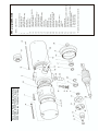
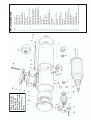
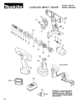
E
C
I
L
V
A
R U E
E
S AN RANG RS
M T/MTS OMOTO
V
M
3
R
E
E
U
S ISS
F
O
WARNING
Servomotors contain magnetic
material which will attract metal
particles. Care should be taken
when dismantling motors to
avoid this.
All D.C. servomotors
manufactured by SEM contain
magnets which are air stable
and can be dismantled without
demagnetisation
MT22
servicing instructions
Before commencing any dismantling it is important to mark the
following relationships with either a marker pen or some similar
method.
a) Commutator end housing to motor body (A to B).
b) Drive end cover to motor body (C to D).
It is advisable to have a suitable stand available to enable the motor
to be handled in a convenient manner to minimise the risk of causing
damage to any components.
DISMANTLING THE MOTOR
1. Remove the brush holder caps (26) and remove the motor
brushes (24), marking both the motor brush and brush holder to
ensure that each brush can be refitted the right way around in its
original holder. Remove cast cover (17), remove encoder adaptor
when fitted, take care whilst dismantling not to damage the ‘O’
rings, encoder and encoder adaptor (when fitted).
REMOVAL OF TACHO ASSEMBLY
2. Mark position of tacho brush gear assembly to retain the
relationship with tacho body assembly (12) for re-assembly.
Clamp drive shaft in mole grips or a bench vice (shaft must be
suitably protected against any damage during this operation)
and remove tacho retaining nut and washer (special tool is
required, available from SEM LTD on request). Remove tacho
brush gear assembly taking care to remove tacho brushes out of
the holders as they are not independently retained. Remove tacho
armature, tacho body and spacer sleeve and store in a safe
place. Unclamp drive shaft.
(b)
MOTORS WITH BRAKES
Assemble wave washer and bearing to drive end cover and re-fit
brake assembly. Position drive end cover over drive shaft and rest
on fixing studs (31). Reconnect brake leads, keeping leads well
away from any moving parts. Reposition drive end cover over
fixing studs and press drive end cover onto armature using a
suitable fixture. Assemble tachogenerator to motor and lock in
position with nut and washer (15 & 16).
(c) When refitting tacho brush gear assembly ensure that spring
tensions are correct, as the tension is slackened when tacho
brushes are removed from their holders. To avoid this occurring
the brushes can be individually captured in their holders by
pushing the tacho brush into the holder and fitting a pin in the
holes provided on the front of brush holder. This can be done
during the dismantling procedure to avoid re-tensioning the brush
spring.
6. In the event of the main armature being changed, the neutral
setting on the motor must be checked. This can be achieved by
applying an appropriate DC voltage (the applied voltage is
dependent upon the maximum voltage listed on the nameplate) to
motor leads and checking that the speed in both directions are
within 30 revs per 1,000 rpm for same applied volts. To increase
speed, loosen the two Nyloc nuts (22) and move body assembly
in the direction of rotation, relative to the commutator end cover.
To decrease speed move body assembly in the opposite direction.
After setting neutral position, torque the Nyloc nuts to 4.75Nm
(31⁄2 lbs ft).
7. Check tacho assembly for correct voltage output and ripple using
a DC volt meter and oscilloscope. To do this motor must be run at
1,000 rpm. If tacho ripple is out of spec (1%), check that the
brush spring is located on the slot provided on tacho brush and
that the brushes are making contact with the commutator.
8. After test fit new Oilseal, Encoders, Adaptors (when fitted) and
Cast cover, refitting ‘O’ rings.
9. Check insulation resistance to earth with a 500 Volt DC megger
meter (the minimum resistance acceptable is 3 mega ohms) for
the following:
- Motor Armature
- Tacho Assembly
3. Remove fixing nuts and washers (22) from drive end cover (see
note for motors fitted with a brake) and remove drive end cover
and motor body assembly. Using a suitable fixture, press out
motor armature. Care must be taken not to damage the threaded
shaft end. Remove circlip holding comm end bearing so that
bearing can be replaced during reassembly Remove oilseal from
drive end cover and discard (oilseal must be replaced after motor
is reassembled).
Note: To dismantle brake motors it is necessary after removing
fixing nuts in drive end cover to separate the drive end cover from
body assembly by approx. 25mm (1") and disconnect the joints in
the brake leads. Using a suitable fixture press out motor armature
from comm end cover (take care not to damage the threaded
shaft end) and remove motor body. The drive end cover and
brake assembly can now be removed. The brake must be
removed from drive end cover to change the drive end bearing.
RE-ASSEMBLY OF MOTOR
4. Bearings and oilseal must be replaced. Examine brushes for wear
and refit or replace if necessary. Care must be taken that no
metal particles have been attracted to any magnetised parts.
5. (a) When using existing armature ensure that all markings are in
line during assembly. Fit bearing and circlip to commutator end
cover, press drive end bearing onto armature and using a suitable
fixture, press comm end cover onto armature. Re-fit body
assembly and drive end cover refitting wave washer at the drive
end. Refit the ‘O’ rings between body assembly and both covers.
SEM Limited, Faraday Way, Orpington, Kent BR5 3QT England
Telephone: +44 (0) 1689 884700 • Fax: +44 (0) 1689 884884
E-mail: [email protected] • Internet: http://www.sem.co.uk
Note. A new Radio Energie Tacho has
been fitted to the MT22 since August
2000. Please see final sheet for details
Motor Armature Assembly
Bearing (Drive End)
Circlip (Drive End)
Bearing (Commutator End)
Wave Washer
Drive End Cover
Body Assembly
Commutator End Cover Assembly
Tacho Body Assembly*
Tacho Armatures*
Tacho Brush Gear Assembly*
Tacho Retaining Washer
Tacho Retaining Nut
Cast Cover (Tacho/Encoder)
Cable Gland
Fixing Stud Nut
Motor Brush
Brush Holder Cap
Brush Holder Cap Cover
Encoder Drive Pin (Optional)
Brush Holder Fixing Screw
Brush Holder
Fixing Stud
Spacer Sleeve (Tacho)
Tacho Brush
Oilseal
Brake (Optional)
Bearing Retainer Cap (Commutator End)
Cast Cover Screws
Encoder Adaptor Fixing Screws (Options
Encoder Adaptor (Optional)
‘O’ Rings (Mating Face)
‘O’ Rings (Brush Holder)
1
2
3
5
7
8
10
11
12
13
14
15
16
17
18
22
24
25
26
28
29
30
31
33
35
36
37
39
41
42
43
44
45
*For spares complete unit has to be purchased.
DESCRIPTION
ITEM No.
MT22 parts list
MT / MTS30
servicing instructions
Before commencing any dismantling it is important to mark the
following relationships with either a marker pen or some similar
method.
a) Commutator end housing to motor body (A to B).
b) Drive end cover to motor body (C to D).
DISMANTLING THE MOTOR
1. Removing the motor brushes (24), seals (25) and caps (26)
marking both the carbon brushes and brush holders to ensure
that the brushes can be refitted in the correct holders and the
correct way around.
2. Remove either the pressed steel or cast cover secured by 4
screws (in some case as encoders and adaptors are fitted these
must also be removed). Important: The tacho brush gear (15) and
comm. end housing (11) must be marked to retain relationship for
re-assembly, again use a scribe or marker pen. Disconnect the
tacho leads from terminal block (when fitted). Now remove the 24mm screws and washers (40) from tacho brush gear and take
out brush gear complete. (Taking care not to damage tacho
brushes) .
3. Remove circlip (4) from front of tacho armature (13) and unscrew
tacho sleeve locking set screws (14) located just in front of the
commutator.
4. Take out tacho armature noting the number and position of
any shim washers both in front and behind the tacho armature
sleeve. To assist with the removal of the tacho armature, leverage
can be applied behind the set screws or directly into the tapped
sleeve holes. Ensure that the set screws have been removed
completely or have been slackened off sufficiently to clear groove
in shaft.
Note:- No shims or circlips were used to locate the tacho
armature on motors produced prior May 1984.
5. Remove the oil seal (when fitted) from the drive end cover. (The
oil seal must always be replaced with a new one when
reassembling). Remove 4-5mm Nyloc nuts (22) from the counter
bored holes in the drive end cover. See note 8 for brake motors.
6. Body (10) and drive end cover (8) can now be separated from the
commutator end housing (11) and main armature (1). The drive
end cover is pinned to the body using roll pin (9).
TAKE CARE.
Note:- Pre May 1984 motors produced for Bridgeport had the
drive end bearing bonded into the drive end cover.
7. To separate the main armature from the commutator end cover
entails the removal of 2-4mm screws and washers (39) locking the
commutator end bearing to the cover. This operation is carried out
using a right angled screwdriver or in case of difficulty the
armature can be pressed out through the bearing affording easy
access to the screws. Ensure tacho pin (33) is removed with a pair
of pliers before pushing out armature. (Prior to May 1984, the
commutator end bearing was not locked, the thrust washer being
fitted at that end.)
RE-ASSEMBLY OF MOTOR
9. Bearings must be replaced whilst brushes can be examined for
wear and replaced if required. Refit Wave Washer (7). Care must
also be taken to ensure no metal particles have been attracted to
any magnetised parts. Important: When pressing on bearings,
pressure must only be applied to the inner race (ring).
10. To reassemble motors using existing armature ensure that all
markings made under note (1) are in line.
Note that the wave washers are at the drive end in all motors
manufactured after May 1984. Ensure before assembly that the
tacho armature drive pin (33) has been refitted to the main
armature shaft. (Bridgeport motors without locked commutator
bearings must have the drive end bearing bonded into the drive
end cover ) When refitting pre May 1984 tachos, i.e. no circlip or
shims, the armature is put on to the shaft without the set screws
being tightened The tacho brush gear is then fitted and the tacho
armature is set along the shaft until the brushes are
approximately 0.25mm from the front edge of the commutator The
two set screws should then be tightened ensuring that the screw
marked by a file mark or red point on the sleeve is tightened first.
11. In the event of the main armature being renewed the neutral
setting of the machine must be checked. This is carried out by
applying a known DC voltage to terminals or leads A1 and A2,
say 50 or 60 volts and checking that the same speed is obtained
in both directions for the same applied voltage. To increase speed
loosen the four Nyloc nuts in the drive end cover and move the
motor body in the direction of rotation relative to the commutator
end cover. To decrease speed move body opposite to direction of
rotation. Maximum speed deviation between the two speeds in
opposite directions should be in the order of 30 revolutions per
1000 R.P.M.
After setting the neutral torque the Nyloc nuts to 4.75Nm
(31⁄2 lbs.ft.).
12. Tacho adjustment is most critical and necessary in all cases.
If the tacho armature is replaced re-setting of the tacho brush
rocker assembly is necessary. To do this, the motor is run at 1000
R.P.M. with a DC Voltmeter and oscilloscope connected to tacho
brush gear leads T1 and T2, with a 0.1 mfd capacitor across T1
and T2.
The oscilloscope is set to AC input, volts/division set to 0.1 and
time base seconds/division closed right down to say 0.2 or 0.5
seconds. Check that when the machine runs clockwise T1 is
positive. The tacho brush gear must be adjusted, by rotation, to
give a minimum ripple voltage height reading in both directions of
rotation. This height should not be greater than 2 x tacho output
volts x 0.01. The height reading with the scope closed down
includes all irregularities such as modulation and spikes.
By opening up the time base to say 5 milli-seconds the actual
shape of the output can be studied and any faults identified.
Spiking or mushiness could indicate that the commutator requires
cleaning. Open circuits will show as a very large irregular pulse
with a break in the continuity of trace, whilst short circuits will
show as large ‘spiking’ pulses. Run motor at maximum speed
(see nameplate) to ensure that spiking does not occur in either
direction. If this does occur clean tacho commutator. Ensure that
the brush gear is secured.
13. Check insulation resistance to earth with a 500 Volt DC Megger
meter. The minimum resistance acceptable is 3 MΩ for the
following:
- Motor Armature
- Tacho Armature
- Thermal overload.
At the same time, check that the thermal overload is closed.
8. To dismantle brake motors it is necessary, after removing the four
Nyloc nuts in the drive end cover, to remove any *circlip and
shims from in front of the drive end bearing. Separate the drive
end cover from the body by approx 40mm (11⁄2") and unsolder or
disconnect the joints made in the brake leads. The drive end
cover, brake and bearing assembly can now be removed. (Prior to
May 1984 motors with integral brake had the drive end bearing
locked between the brake and cover on the outside diameter and
between a shaft spacer and circlip on the shaft. On this style of
motor if the cover, brake and bearing assembly fail to separate
from the main armature the armature can be pressed out.
*Circlip not fitted to press fit bearing
SEM Limited, Faraday Way, Orpington, Kent BR5 3QT England
Telephone: +44 (0) 1689 884700 • Fax: +44 (0) 1689 884884
E-mail: [email protected] • Internet: http://www.sem.co.uk
Note. A new Radio
Energie Tacho has
been fitted to the
MT30 / MTS30 since
August 2000. Please
see final sheet for
details
ITEM
1
2
3
4
5
6
7
8
9
10
11
12
13
14
15
16
17
18
19
20
21
22
23
24
25
26
27
28
29
30
31
32
33
34
35
36
37
38
39
40
DESCRIPTION
Armature Assembly
Bearing (Drive End)
Circlip Drive End
Tachogenerator Circlip
Bearing (Commutator End)
Circlip Commutator End
Wave Washer
Drive End Cover
Spring Dowel (D.E. Cover Location)
Body Assembly
Commutator End Cover Assembly
Tachogenerator Body Assembly
Tachogenerator Armature Assembly
Tacho Armature Retaining Screw
Tachogenerator Brush Gear Assembly
Cover Plate Gasket
Cover Plate
Terminal Box
Terminal Box Gasket
Terminal Box Lid
Terminal Box Lid Gasket
Fixing Stud Nut/Sealoc Washer
Terminal Block
Motor Brush
Insert
Brush-Holder Cap & Disc
Earth Screw
Encoder Drive Pin
Brush-Holder Fixing Screw
Brush-Holder
Fixing Stud
Terminal Box Fixing Screw
Tachogenerator Drive Pin
Tachogenerator Body Fixing Screw
Tachogenerator Brush
Oilseal (Optional)
Brake (Optional)
Thermal Overload
Washer, Bearing Retainer
Tachogenerator Brush Gear Fixing Screws
MT30 parts list
MT40
servicing instructions
The MT40 Servomotor is a locked drive end bearing motor with the
tacho armature located and locked in position on the shaft by two set
screws.
Before commencing any dismantling it is important to mark the
following relationships with either a marker pen or some similar
method.
1. (a) Commutator end housing to motor body (A to B). (b) Drive end
cover to motor body (C to D).
DISMANTLING THE MOTOR
2. Remove the motor brushes (24), seals (25) and caps (26)
marking both the carbon brushes and brush holders to ensure
that the brushes can be refitted in the correct holders and the
correct way around.
3. Disconnect the tacho leads from the terminal block (23), when
fitted, and remove either the pressed steel or cast cover (17),
secured by 4 screws (in some cases an encoder and adaptor are
fitted and these must also be removed). Important. The tacho
brush gear and the commutator housing must be marked to retain
relationship for reassembly. Again use scribe or marker pen. Now
remove the 2-4mm screws and washers (40) from the tacho
brush gear and take out brush gear complete. (On earlier model
motors the tacho brush gear and tacho body were secured by two
protruding studs with nuts and washers clumping the two parts to
the commutator end cover )
4. Unscrew the two tacho sleeve set screws (14) located just in front
of the commutator, and remove tacho armature. To assist with the
removal of the tacho armature, leverage can be applied behind
the set screws or directly into the tapped sleeve holes (with set
screws removed) ensuring that either the set screws have been
removed completely or have been slackened off sufficiently to
clear the groove in the shaft.
5. Remove the oil seal (when fitted) from the drive end cover The oil
seal must always be replaced with a new one when reassembling. Remove circlip and shim washers used to lock drive
end bearing axially on the shaft Remove 4-6mm Nyloc nuts (22)
from the counterbored holes in the drive end cover
6. Using a rubber or hide mallet separate commutator end housing
(11) from the motor body assembly (10), and remove commutator
end housing (See note 7 for brake motors). Separate and remove
body assembly (10) from drive end cover (8). The drive end
cover is pinned to the body assembly using roll pins. Take
care. Press or tap off drive end covers and bearing from armature
assembly (1). Remove circlip, shims and bearing from drive end
cover and take out tacho drive pin (33) and remove commutator
end bearing (5).
7. To dismantle brake motors after removing the Nyloc nuts (22)
separate commutator end housing (11) from body assembly (10)
as far as brake leads slack allow. Using rubber or hide mallet tap
drive end cover to allow for leverage of body assembly. Lever
body assembly to form a gap of 60mm (21⁄2") and fit spacers to
hold in position. Disconnect or unsolder joints in brake leads.
Remove commutator end housing and body assembly then press
or tap off drive end cover and brake assembly. (Care to be taken
not to damage the brake). Remove brake assembly from drive
end cover (secured to cover by 6 screws in the front face of
cover) to change drive end bearing.
RE-ASSEMBLY OF MOTOR
8. Bearings and oil seals must be replaced whilst brushes can be
examined for wear and replaced if required. Refit wave washer at
the commutator end. Care must also be taken to ensure no metal
particles have been attracted to any magnetised parts. Important:
When pressing on bearings, pressure must only be applied to the
inner race (ring).
9. To reassemble motor using the existing armature ensure that all
markings made under notes (a) and (b) are in line. Ensure before
assembly that the tacho armature drive pin has been refitted to
the main armature shaft. The drive end bearing is located in the
drive end cover, shimmed to eliminate axial movement and locked
by an internal circlip (4) in the end cover bore. Press drive end
cover assembly and comm. end bearing (5) onto armature (1)
shaft. It is necessary after assembling the drive end cover to shim
out the axial end play by fitting shims between bearing and
circlips (3). Refit body assembly and commutator end housing,
using an old tacho armature or bung located in the tacho body
assembly (12) to centralise the armature during the assembly. On
brake motors, a spacer must be used to separate the body
assembly and drive end cover by 60mm (21⁄2"). Refit commutator
end housing (see note regarding centralising the armature) and
reconnect or solder brake lead joints. Take care to insulate the
joints and that the leads are tucked well away from any moving
parts. To assist when fitting brake and end cover assembly on to
brake hub, a voltage should be applied to brake leads (see motor
nameplate for correct Voltage).
10. When refitting the tacho armature, the armature is put onto the
shaft without the set screws being tightened. The tacho brush
gear is then fitted and the tacho armature is set along the shaft
until the brushes are approximately 0.25mm from the front edge
of the commutator. The two set screws should then be tightened
ensuring that the screw marked by a file mark/red paint on the
sleeve is tightened first. Ensure that the brush gear is lined up (as
note 3).
11. In the event of the main armature being renewed the neutral
setting of the machine must be checked. This is carried out by
applying a known DC voltage to terminals or leads A1 and A2,
say 80 or 90 volts and checking that the same speed is obtained
in both directions for the same applied voltage. To increase speed
loosen the four Nyloc nuts in the drive end cover (C) and move
the motor body in the direction of rotation relative to the
commutator end cover. To decrease speed move body opposite to
direction of rotation. Maximum speed deviation between the two
speeds in opposite directions should be in the order of 30
revolutions per 1000 R.P.M. After setting the neutral, torque the
Nyloc nuts (22) to 7.5Nm (51⁄2 Ibs. ft.).
12. Tacho adjustment is most critical and necessary in all cases.
If the tacho armature is replaced re-setting of the tacho brush
rocker assembly is necessary. To do this, the motor is run at 1000
R.P.M. with a DC Voltmeter and oscilloscope connected to tacho
brush gear leads T1 and T2, with a 0.1 mfd capacitor connected
across T1 and T2.
The oscilloscope is set to AC input, volts/division set to 0.1 and
time base seconds/division closed right down to say 0.2 or 0.5
seconds. Check that when the machine runs clockwise T1 is
positive.
The tacho brush gear must be adjusted, by rotation, to give a
minimum ripple voltage height reading in both directions of
rotation. This height should not be greater than 2 x tacho output
volts x 0.01. The height reading with the scope closed down
includes all irregularities such as modulation and spikes. By
opening up the time base to say 5 milliseconds the actual shape
of the output can be studied and any faults identified. Spiking or
mushiness could indicate that the commutator requires cleaning.
Open circuits will show as a very large irregular pulse with a
break in the continuity of trace, whilst short circuits will show as
very large ‘spiking’ pulses. Run motor at maximum speed (see
nameplate) to ensure that spiking does not occur in either
direction. If this does occur clean tacho commutator. Ensure that
the brush gear is secured.
13. Check insulation resistance to earth with a 500 Volt DC Megger
meter. The minimum resistance acceptable is 3 MΩ for the
following:
- Motor Armature
- Tacho Armature
- Thermal overload.
At the same time, check that the thermal overload is closed.
SEM Limited, Faraday Way, Orpington, Kent BR5 3QT England
Telephone: +44 (0) 1689 884700 • Fax: +44 (0) 1689 884884
E-mail: [email protected] • Internet: http://www.sem.co.uk
ITEM No.
1
2
3
4
5
6
7
8
9
10
11
12
13
14
15
16
17
18
19
20
21
22
23
24
25
26
27
28
29
30
31
32
33
34
35
36
37
38
40
41
DESCRIPTION
Armature Assembly
Bearing (Drive End)
Circlip Drive End
Circlip Drive End
Bearing (Commutator End)
Circlip Commutator End
Wave Washer
Drive End Cover
Spring Dowel (D.E. Cover Locution)
Body Assembly
Commutator End Cover Assembly
Tachogenerator Body Assembly
Tachogenerator Armature Assembly
Tacho Armature Retaining Screw
Tachogenerator Brush Gear Assembly
Cover Plate Gasket
Cover Plate
Terminal Box
Terminal Box Gasket
Terminal Box Lid
Terminal Box Lid Gasket
Fixing Stud Nut/Sealoc Washer
Terminal Block
Motor Brush
Insert
Brush-Holder Cap & Disc
Earth Screw
Encoder Drive Pin
Brush-Holder Fixing Screw
Brush-Holder
Fixing Stud
Terminal Box Fixing Screw
Tachogenerator Drive Pin
Tachogenerator Body Fixing Screw
Tachogenerator Brush
Oilseal (Optional)
Brake (Optional)
Thermal Overload
Tachogenerator Brush Gear Fixing Screws
‘O’ Ring
MT40 parts list
MT52
servicing instructions
The ‘52’ series servomotors is a locked drive end bearing motor, with
the tachogenerator armature located and locked in position on the
armature shaft by two set screws.
Due to the physical size and weight of the motors; it is advisable to
have a suitable stand to enable the motors to be handled in a
convenient manner. This will also help to minimise the risk of damage
during dismantling and re-assembly.
1. Before commencing any dismantling it is important to mark the
following relationships with either a marker pen or some similar
method.
a) Commutator end housing to motor body (A to B).
b) Drive end cover to motor body (C to D).
DISMANTLING THE MOTOR
2. Remove caps (26), seals (25) and brushes (24) marking both
the carbon brushes and brush holders to ensure that the
brushes can be refitted in the correct holders and correct way
around.
3. Disconnect the tacho leads from terminal block (23) when fitted.
Remove the steel covers or encoder and adaptor plate assembly
secured by 4 screws to end of commutator end housing.
IMPORTANT: The Tacho brush gear and commutator end
housing must be marked to retain relationship for reassembly
Again use a marker pen or scribe. Now remove the two 4mm
screws and washers securing the tacho brush gear assembly and
take out brush gear complete, taking care not to damage the
tacho brushes.
4. Unscrew the two tacho set screws (14) located in front of the
commutator and remove the tacho armature. (To assist in the
removal, leverage can be applied behind the set screws or
directly into the tapped holes wish set screws removed). Ensuring
that the set screws are either removed completely or slackened
sufficiently to clear the groove in the shaft.
5. Position motor vertically on drive end cover on a suitable stand.
Remove the 4 Nyloc nuts (22) and flat ended washers from the
radial slots in commutator end housing. Disconnect the brake
leads from terminal block (23) when brake fitted. Remove the
commutator end housing taking care not to lose the wave washer
(7) from the non drive bearing housing.
6. With a suitable stand to support the body and armature assembly
in a horizontal position using a rubber or hide mallet ease the
drive end cover off the locating pins (9). Relocate the motor in the
vertical position and remove body assembly (care to be taken not
to trap hands or fingers when removing body assembly due to the
magnetic pull between components).
7. Supporting armature in a horizontal position.
(a) On non brake motors remove the three screws (41) holding
the inside end cap (39) and remove the drive end cover. Remove
circlip (3) and remove bearings.
(b) On brake motors remove the six screws holding the brake (37)
to the drive end covers and disconnect the brake leads and
remove the drive end cover.
RE-ASSEMBLY OF MOTORS
8. Bearings and oilseals (when fitted) must be replaced, whilst
brushes can be examined for wear and replaced if required. Care
to be taken that no metal particles have been attracted to any
magnetised parts.
IMPORTANT: When pressing on bearings, pressure must only be
applied to the inner race (ring).
9.
(a) With the bearing locking cap (39) in position at the drive end press
bearings onto armature shaft. Refit circlip (3) and tacho drive pin (33).
Assemble drive end cover (8) to armature lining up locking cap holes
wish drive end cover holes by using a short stud and refit the three
screws (45). Stand the assembly vertically with drive end shaft down.
Slide body assembly (10) over the armature (take care of magnetic
pull, see note 6) and locate on drive end cover ensuring the correct
alignment. Stand the assembly vertically, with drive end shaft down.
Refit commutator end cover over the fixing studs (31) ensuring that
the wave washer (7) is in position and fit to motor body, taking care to
align markings as in operation 1. Lock commutator end cover with flat
sided washer and fixing stud nuts (22).
b) On brake motors. Assemble brake to armature and press on
bearings. Refit circlip and tacho drive pin. Refit drive end cover to
armature, locate brake in original position, refit the four screws
and secure to drive end cover. Reconnect brake leads, insulate
joint and keep any slack away from the armature. Refit body
assembly and commutator end cover as in operation (a) ensuring
that the brake leads are passed through into the terminal box
whilst assembling the comm end cover.
10. Refit motor brushes, sealing discs and caps. Assemble tacho
armature and locate on drive pin (33), refit tacho brush gear to
tacho body (12) passing leads through into terminal box, align
with markings and secure tacho brush gear. Adjust position of
tacho armature so that brushes are approximately 0.10mm for the
front edge and lock set screws, tightening up screw marked with
red paint or a file mark on tacho sleeve and then tighten up the
apposition screw.
CHECK SPEED, CURRENT AND TACHO
RIPPLE
11. (a) Apply 90 Volts DC to terminals A1 & A2 with A2 supplied
positive the motor should run anti-clockwise. Check speed and
current.
(b) Reverse motor (i.e. A1 positive). Check speed and current at
90 Volts DC. If the two speeds are within 20 revolutions per 1,000
then the neutral setting is acceptable. If not, to alter speed loosen
off nuts (22) and move commutator end cover away from the
direction of rotation to decrease speed. After setting the speed
tighten down the nuts (6) to 13.5Nm (10lbs. ft.).
TACHO ADJUSTMENT
12. Tacho adjustment is most critical and necessary in all cases.
If the tacho armature is replaced resetting of the tacho brush
rocker assembly is necessary. To do this, the motor is run at
1,000 rpm with a DC voltmeter and oscilloscope connected to the
tacho brushgear leads T1 & T2 with a 0.1 mfd capacitor
connected across the tacho leads. The oscilloscope is set to AC
input, volt/division set to 0.1 and time base set to say 0.2 or 0.5
seconds. Check that when the machine runs clockwise T1 is
positive. The tacho brushgear must be adjusted, by rotation. To
give a minimum ripple voltage height in both directions of rotation.
This height should not be greater than 2 x tacho output volts x
0.01. The height reading with the scope closed down includes all
irregularities such as modulation and spikes. By opening up the
time base to say 5 milliseconds the actual shape of the output
can be studied and any faults identified. Spiking or mushiness
could indicate that the commutator requires cleaning. Open
circuits will show as a very large irregular pulse with a break in
the continuity of trace, while short circuits will show large ‘spiking’
pulses. Run motor at maximum speed (see nameplate) to ensure
that spiking does not occur in either direction. If this does occur,
clean tacho commutator. Ensure that the tacho brushgear is
secure.
13. Check insulation resistance to earth with a 500V DC megger
meter. The minimum resistance acceptable is 3MΩ for the
following:
- Motor Armature
- Tacho Armature
- Thermal Overload
At the same time check that overload is closed.
14. Refit steel cover and dowel pins. Seal bearing locking cap screws
and dowel pin with sealant – fit oilseal if required.
SEM Limited, Faraday Way, Orpington, Kent BR5 3QT England
Telephone: +44 (0) 1689 884700 • Fax: +44 (0) 1689 884884
E-mail: [email protected] • Internet: http://www.sem.co.uk
ITEM No.
1
2
3
5
7
8
9
10
11
12
13
14
15
16
17
18
19
20
21
22
23
24
25
26
27
28
29
30
31
32
33
34
35
36
37
38
39
40
41
42
43
44
45
DESCRIPTION
Motor Armature
Bearing Drive End
Circlip Drive End
Bearing Commutator End
Wave Washer
Drive End Cover
Spring Dowel (D.E. Cover Location)
Body Assembly
Commutator End Cover Assembly
Tacho Body Assembly
Tacho Armature Assembly
Tacho Armature Retaining Screw
Tacho Brush Gear Assembly
Tacho Cover Plate Gasket
Tacho Cover Plate
Terminal Box
Terminal Box Gasket
Terminal Box Lid
Terminal Box Lid Gasket
Fixing Stud Nut
Terminal Block
Motor Brush
Insert
Brush-Holder Cap & Disc
Earth Screw
Encoder Drive Pin
Brush Holder Fixing Screw
Brush Holder
Fixing Stud
Terminal Box Fixing Screws
Tacho Drive Pin
Tacho Body Fixing Screws
Tacho Brush
Oilseal (Optional)
Brake (Optional)
Thermal Overload
Bearing Locking Cap
Tacho Brush Gear Fixing Screws
Blower Plate & Gasket
Terminal Block Fixing Strip
Terminal Box Base
Terminal Box Base Gasket
Drive End Bearing Locking Cap Screws
MT52 parts list
IMPORTANT. CHANGE TO TACHO SPECIFICATION.
In order to concentrate our production efforts directly on the production of servomotors we no
longer make and fit the SEM tacho to certain products in our range.
In place of the SEM tacho we now fit a tacho made by the company Radio Energie.
Please note the following changes to motor specifications:
MT22 series.
The Radio Energie tacho was introduced to this motor series in August 2000.
The assembly sequence for the Radio Energie tacho differs slightly from the SEM unit in that the
armature is assembled first and then the integral body/brushgear assembly.
As an assembly the Radio Energie tacho is directly interchangeable with the SEM unit ,however
the individual components and brushes are not.
MT30 series.
The Radio Energie tacho was introduced to this motor series in August 2001.
The Radio Energie tacho is not interchangeable with the SEM unit, however the SEM unit will be
made available for spares requirements for some time to come.
MTS30 series.
The Radio Energie tacho was introduced to this motor series in August 2001.
The assembly sequence for the Radio Energie tacho differs slightly from the SEM unit in that the
armature is assembled first and then the integral body/brushgear assembly.
As an assembly the Radio Energie tacho is directly interchangeable with the SEM unit ,however
the individual components and brushes are not.
MT40 series.
The SEM tacho will continue to be fitted to this series.
MT52 and DBMT52 series.
The SEM tacho will continue to be fitted to this series.
If you require further information regarding the tacho fitted to our brushed servomotor series
please contact our Service Dept.
WARNING
Servomotors contain magnetic material
which will attract metal particles. Care
should be taken when dismantling motors to
avoid this.
All D.C. servomotors manufactured by SEM
contain magnets which are air stable and
can be dismantled without demagnetisation
SEM Limited, Faraday Way,
Orpington, Kent BR5 3QT England
Telephone: +44 (0) 1689 884700
Fax: +44 (0) 1689 884884
E-mail: [email protected]
Internet: http://www.sem.co.uk
UL VERSIONS
AVAILABLE