1
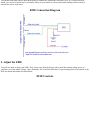
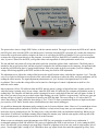
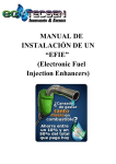
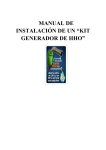
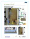
Affiliates Store Forums Documents
EFIE Installation Instructions
It would be a good idea to familiarize yourself with what an EFIE is by reading the following two documents:
Oxygen Sensor Adjustment - General Information
EFIE: Electronic Fuel Injection Enhancer, Described
Also, if you are installing a version other than a Deluxe Series EFIE then see the document, Notes For Installing Circuit
Board & Basic EFIE Models.
0. Install your fuel efficiency device
The EFIE is not intended to be a fuel saver by itself. You should install a device that is designed to get more energy out of
the same fuel, such as a hydrogen gas electrolyzer, a fuel vapor production unit, or other device that gets more power out of
the same fuel by increasing the efficiency of the burn.
1. Locate the oxygen sensor signal wire
The easy way to do this is to look it up in your Haynes, Clymer or Chilton manual for your car. If you don't have one of
these, there is a service at www.ahdol.com
where you can pay a nominal fee, and get your wiring diagrams emailed to you. I have also recently found a resource at
www.autozone.com
whereby you can get your wiring diagram, and specific service manual information on your sensors. However, the
information is not available for all cars and trucks. To help you find your wiring diagram at autozone.com, follow the
instructions found here. Using the wiring diagram data, you can get the wire color of the signal wire, and hopefully gain
access to it up in the engine compartment, where it routes to the computer.
If none of these options are available, you'll need to locate the oxygen senor and then locate the signal wire by testing. The
sensor can have 2, 3 or 4 wires, and you have to know which one is the signal wire. If you have 4 wires they will be:
1.
2.
3.
4.
Heater 12 Volts +
Heater ground
Oxygen sensor signal +
Oxygen sensor signal ground
If you have 2 or 3 wires, then you can have a common ground, or no heater wires etc. The simplest setup is a single wire,
which is the signal wire and the sensor get's it's ground from the exhaust pipe. You can use the following procedure to
narrow down which wire is which:
1. Disconnect the wire harness, turn on the ignition and probe for a wire produces 12 volts. This will be the heater
circuit.
2. Next find the 2 wires that produce exactly 0 volts. These will be the heater ground and the signal ground. The
remaining wire should be your signal wire.
3. Reconnect the wiring harness, then strip a little insulation from the signal wire and measure it to ground with the
engine running. You'll get voltage readings constantly fluctuating between 0 and 1 volt, if you have the signal wire.
Note, that you have to let the engine warm up a bit before you will get these voltages from the sensor.
Cut this wire at a convenient location for connecting the EFIE. We'll call the sensor side of this cut the sensor wire,
and the other side of the cut, the computer wire.
Note: rarely an oxygen sensor wiring harness will have more than 4 wires. In this case, the sensor is possibly a "wide band"
oxygen sensor. The EFIE has been reported to work with 5-wire wide band sensors.
Once you have determined which is the sensor's signal wire, you want to get it located up close to the computer. If you used
a manual, or wiring diagram, you probably have already located the wire at the computer's wiring harness. If you had to
figure out the wires at the sensor itself, then try to find the same wire at the computer's wiring harness. It should be the same
colors, but test it with an ohm meter to be sure. Sometimes they use the same colors for different things. Even if it's a pain
now, it's worth it to get the signal wire located up by the computer. This makes cutting into it and hooking up the EFIE
much easier.
2. Locate 12 volt power and ground
You need to ensure that you have switched power, not power directly from the battery. You don't want the EFIE running
100% of the time. It's not that the unit couldn't run 100% of the time, it probably could. But it would slowly drain your
battery.
Most of the fuel efficiency devices need switched power as well, and you can often piggy back onto them. Note that the
EFIE draws negligible power. You can attach it to any circuit. The best choice for a voltage source is a fuel efficiency
device, such as a Hydrogen generator. That way the EFIE only activates when the fuel efficiency device is turned on. Note
that when power is shut off to the EFIE, or the EFIE's switch is turned off, the original connection between the oxygen
sensor and the computer is re-established. If connecting to your fuel saver's power is inconvenient or inappropriate, just use
any circuit that is accessory key switched. Your electrical diagram can come in handy here, and if you don't find another
device to attach to, you can usually find a spare circuit in the fuse box (you may have to add a fuse). One installer used the
oxygen sensor's heater power for his EFIE's power, and this is perfectly acceptable.
Ground can be the vehicle body, engine block or ground from another device, including the ground for the oxygen sensor
itself. Just make sure that whatever you choose to use for ground has a negligible resistance (less than 10 ohms) when tested
against the negative battery terminal of your car.
3. Mount the EFIE
You can use the mounting ears to screw down the EFIE to a suitable location on the vehicle body or firewall. Some people
like to mount the device inside the passenger compartment of the car. There are some considerations about where you mount
your EFIE that should also be reviewed:
1. The EFIE is not waterproof. If you mount it under the hood, you will have to take care to cover it if you need to steam
or spray clean your engine. If this is something you regularly do, you may want to mount the EFIE in the passenger
compartment where it will be protected.
2. If you live in a cold climate, where temperatures are expected to be below freezing a significant number of days per
year, you will want to ensure that the EFIE is mounted where it will be warmed, either by the engine, or inside the
passenger compartment. Below freezing temperatures cause the EFIE to come up to it's voltage offset very slowly
unless it is physically warmed. This is because it doesn't generate much heat of it's own. In most cases this can be
accomplished by mounting your EFIE in the upper rear of the engine compartment, close to the firewall, which will
allow it to benefit from trapped engine heat. Newer EFIEs now come with jumpers that if set will cause the EFIE to
generate more heat. These were intended for use in very cold climates. Find J1 and J2 on your circuit board. Set the
following jumpers for increasing amounts of heat: J1, J2, J1 and J2.
4. Attach the wires
The EFIE multi-conductor wire has 6 colors: red, black, white, green, blue and brown. Connect the red to your power
source. Connect the black to ground. Connect the green wire to the oxygen sensor. Connect the white wire to the computer.
For Dual EFIE units, the brown wire goes to the 2nd oxygen sensor, and the blue wire goes to the 2nd sensor's computer
line. Hopefully you've been able to locate all these wires up by the computer in an easily accessible location. But if so, be
sure not to cut them too close to the computer so that you have plenty of slack to work with them.
You should solder them and use heat shrink tubing to insulate the connections from other wires. If you don't have heat
shrink, you can use electrical tape. I personally always use heat shrink. It's more professoinal looking, and less likely to
unravel later into a sticky mess.
EFIE Connection Diagram
5. Adjust the EFIE
You will now need to adjust your EFIE. They do not come from the factory with a particular starting voltage preset, so
you'll have to set the intitial voltage. I have found that .200 volts (200 millivolts) is a good starting point. The controls of the
EFIE are shown and further described below:
EFIE Controls
The picture above shows a Single EFIE Deluxe, with the controls marked. The toggle switch turns the EFIE on/off, and the
red LED glows only when the EFIE is on and has power. Note that when the EFIE is powered off, it makes the connection
between the oxygen sensor and the computer, the same as it was before the EFIE was installed. If you ever have need to
reconnect the oxygen sensor directly to the computer, just turn the EFIE (or Dual EFIE) off, and this will be accomplished.
Also, if power is shut off to the EFIE, you'll get the same result regardless of which position the switch is in.
The red and black test points will accept and hold in place the electrodes (probes) from a multi-meter. The black point is
attached to the oxygen sensor lead, and the red point is attached to the lead that outputs to the computer. Just push the leads
in and they will be held in place by spring loaded clamps. With your probes in the two test points, you'll be reading the
voltage offset being supplied by the EFIE, and this is the setup you need for EFIE adjustment.
The adjustment screw adjusts the voltage offset between the signal from the sensor, and what the computer "sees". Turn the
screw in a clockwise direction to increase the offset, and counter-clockwise to reduce the offset, and your multimeter will be
reading the offset amount. The signal adjustment potentiometer (or "pot" for short) is designed to turn 18-20 full
revolutions. This is so that the voltage offset can be tuned to a fine degree of control. Adjustments as small as a few
millivolts can be made.
Most computers will see 425 millivolts from the EFIE, plus the sensor's voltage as high all the time. In other words even
when the sensor is putting out it's lowest voltage, when the EFIE adds 425 millivolts, the computer will think the sensor is
reading high. The computer will think the sensor is damaged, because it reads high all the time, and will ignore it's data. If
this occurs you may or may not get a check engine light alerting you to the "defective oxygen sensor", but for sure your gas
mileage will get very bad. So you should never operate your EFIE this high. The exact voltage is .45 volts to the ECU.
Above that voltage is "high" and below that voltage is "low". The ECU must see transitions from low to high several times
per second or it will "know" that the sensor is bad and then just start merrily adding gas.
It is possible to damage the adjustment pot by turning it past it's lowest or highest values. However, I've turned them at least
10 full revolutions past the end with no ill effects. But there is a limit to how many times you can turn them, and I have
ruined one once by turning one too far. The thing to do, is only turn them with your multimeter hooked up. When you get
down below 50 millivolts, and further turning doesn't change the amount, stop. And the same applies at the top end of the
scale. In actual practice you should never need to be at the extremes.
When it comes to making the actual adjustments to the EFIE for your particular car and fuel saver combination, I
recommend starting out with 200 millivolts. The process of adjusting the EFIE is trial and error. If you're setting the EFIE
above 350 millivolts you're starting to get pretty high. Watch for symptoms of too lean a mix such as rough engine, lack of
power, "check engine light" coming on, etc. When these show up, adjust it back down until the symptoms go away. Note,
some computers will accept an EFIE setting of over 400 millivolts. This is not the norm however, unless you take some of
the actions in Tuning For Mileage.
A couple of adjustment tips: 1) If your "check engine" light comes on, you've likely set the offset too high, and the computer
thinks your oxygen sensor is on the fritz. This can also be caused by mis-wiring the EFIE, so make sure you're hooked up
correctly. 2) If you lose horsepower, you've got an incorrect setting, as fuel efficiency devices should increase horsepower
proportionately with the increase in MPG (as well as decrease emissions). 3) If you have a high temperature probe, run
down the highway with the fuel efficiency devices turned off, long enough to get the engine up to full operating
temperature, and note the temp of your exhaust pipe, near the exhaust manifold. As you increase your voltage offset, this
temperature may increase. Don't let it raise more than 180 degrees from your initial test.
You will probably find adjusting the EFIE to be frustrating at first. When you turn the adjustment screw, the voltage starts
raising (or lowering) and keeps on doing so long after you've stopped turning the screw. It can take up to 10 minutes or
more for the voltage changes to completely settle down. I have learned to set EFIEs similarly to balancing a long stick on
your finger. You have to turn the screw farther than you expect the final position to be to get the EFIE's voltage changing in
the direction you want. Then when the voltage gets close to your target voltage, quickly start turning the adjustment screw
the opposite way until the voltage stops increasing. Once the voltage is at your target value, then you just make small
adjustments either way to get the voltage to settle down. But note you'll want to check the voltage some minutes later to
make sure it hasn't continued to drift to a different value.
Another small detail that might throw you if I didn't point it out. When an EFIE is first connected to a vehicle and powered
up, the voltage will go higher than normal, and then slowly settle back down. This is without changing the adjustment. This
settling out period can take from 5 to 10 minutes or more. The primary manifestion of this is when you make your first
voltage setting, then 5 minutes later find it has changed. This is normal. Just go ahead and re-set the voltage you want. After
the EFIE is acclimatized to your vehicle you won't see this phenomona again.
That's the basics. If you run into trouble in your installation, post questions on the support forum, www.fuel-saver.org. I can
use the feedback to improve the guides here, as well as answer questions others may have as well.
Good luck!
Documents Store Forums FAQ Links Affiliates Contact/Support
© 2007-2008 FuelSaver-MPG.com.