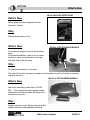
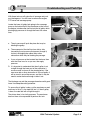
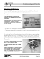
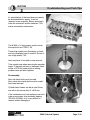
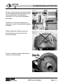
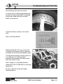
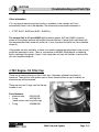
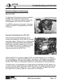
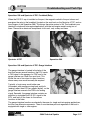
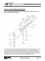
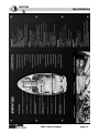
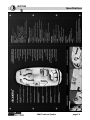
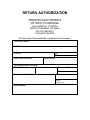
1
Index
2004 Technical Update Book
Bombardier Recreational Products Inc. is proud
to introduce the 2004 BOMBARDIER SPORT
BOAT Technical Update Book.
General Information
Section 1
What's New
Section 2
Again this year, you are given the opportunity to
test on the B.R.P.T.I. web site:
Troubleshooting and
Tech Tips
Section 3
www.brpti.brp.com
Special Tools
Section 4
Specifications
Section 5
Annexes
STEP BY STEP TO DO THE EXAM:
Go to the the B.R.P.T.I. web site: www.brpti.brp.com
If you are not registered click on:
"New to B.R.P.T.I. CLICK HERE …"
If you are already registered to B.R.P.T.I. you need to enroll to:
2004 Sport Boat Technical Update.
1. Use your B.R.P.T.I. login name and password to enter the B.R.P.T.I. web site.
2. In the "Favorites" box, click on "Courses"
3. Check "English", click on "GO"
4. Choose "2004 Sport Boat Technical Update" course by clicking on the yellow folder next
to it.
5. Click on "Enroll" at the bottom of the screen
6. Click on "learning environment" (in white)
7. You are now back to your learning environment; click on "2004 Sport Boat Technical
Update" to begin the exam.
The passing grade is 75%
Notes: You always have three (3) opportunities to take an exam. If you do not pass after three
attempts, you will be restricted from taking the exam for a period of 30 days. During the 30
days, you should study the course, review the material, then re-test.
SECTION
1
2004 Technical Update
General Information
The objective of Section 1 is to make contacts
between dealers and BRP as easy as possible.
In Section 1 you will find the most important
phone numbers, key contact names and the
latest updated procedures to help you be more
efficient.
One Toll Free Number
Page 1-3
Before You Call…
Page 1-4
Who's Who
Page 1-5
Warranty Parts Return
Page 1-8
Radio Warranty and Repair
Page 1-9
Trailers Warranty and Repair
Page 1-10
Explorer Tube Warranty and Repair
Page 1-10
Fiberglass Warranty and Repair
Page 1-10
Boat Information
Page 1-11
RPQ Reporting
Page 1-12
PDI
Page 1-13
Electronic Parts Catalog
Page 1-14
BOSSWeb Tips & Tricks
Page 1-15
What’s News Letter
Page 1-16
Book, DVD and Shop Manual
Quick P/N Reference
Page 1-17
Accident Procedure
Page 1-19
SECTION
General Information
1
IT’S EASY TO REACH US
The Dealer Network Support Group has a consolidated structure that combines all of our core
services, thus allowing you easy access to eleven services with ONE TOLL FREE NUMBER.
Just dial:( One Toll-Free Number
From
From
U.S.:
Canada:
1-800-366-6992
(1-800-361-9980
(
For Dealer use only
For Dealer use only
It’s Quick and Easy
BRP Network Support
Shortcut path using
Service
phone keys
1-1
This is the new phoning procedure for contacting
us:
PAC
Technical
Service
Dial the same numbers:
Enter your BRP dealer number to access your support
services.
Warranty
Listen to the first menu and choose the service by
pressing the number key on your telephone.
Listen to the second menu tone and choose the
appropriate subject category.
These phone numbers are for dealer use only: Do
not give these phone numbers to customers as
this will have a serious impact on your ability to
reach us.
1-2
2-1
2-2
2-3
2-4
3-1
3-2
BOSSWeb
and
Technology
Support
4
5-1
Sales
Coordinator & 5 - 2
Vehicle
5–3
Shipping
5-4
6–1
6–2
All Other
6–3
Services
6–4
6-5
2004 Technical Update
PAC Analysts
PAC & BEST Sales
Information
Technical Ski-Doo
Technical Sea-Doo
Technical ATV
Technical Sport Boat
Warranty Vehicles and
Parts
Clothing Warranty
BOSSWeb and technology
Support (Including BUDS,
PACPro & EPC)
If you know your Regional
Coordinator extension…
US Dealer Coordinators
Canadian Dealer
Coordinators
Vehicle Shipping
Consumer Assistance
BPR Pro
Signage and Co-op
Dealer Certification
Training B.R.P.T.I.
page 1-3
SECTION
General Information
1
Before You Call the Service Department :
Be prepared :
The BRP Service Department values your call. In fact, you are the reason that we are here!
Your input and information are vital to our department, and accuracy is critical. In an effort to
provide the best service to you, we ask you to observe the following guidelines:
Review the service material that you already have :
Check your service library for any publications that may assist you with your problem. Often
the answer is already in your hands in the form of manuals, bulletins, spec books, etc.
Check BOSSWeb :
All bulletins and campaigns can be found on BOSSWeb. Verify the unit history on each
vehicle to see if there are any pending campaigns.
Have vital information close at hand :
You will always be asked for your dealer number, the vehicle model, serial number and the
vehicle mileage/hours. You will also be asked if there is already a call identification number
logged on the vehicle or customer in question. Not having this information readily available is
very common and slows the system down for everybody.
Verify the customer's complaint :
If you are contacting your Service Representative for assistance, you should be able to
describe the problem accurately, with factual information.
Verify the warranty status :
Is the unit in warranty, out of warranty, or covered by a BEST contract? If it is covered by
BEST, have the contract number available as well as maintenance history if available.
Take names and Call ID:
Every BRP representative will identify themselves when answering your call. Do not complete
the call without noting who you spoke with. Your call will also be logged in the computer
system. Make sure you ask for the call I.D. number and put it on the repair order.
2004 Technical Update
page 1-4
SECTION
General Information
1
"Who's Who": Dealer Technical Support
Call the Service Reps to get technical assistance and to get a Warranty authorization number.
( (715) 842-8886
Rich Klein Manager
L
(715) 847-6879
Service Representatives:
(
U.S.:
Canada:
(800) 366-6992
(800) 361-9980
L
U.S.:
Canada:
(715) 847-6879
(819) 566-3062
Alain Doucet (English / French)
Mike Carter (English)
Claude Beaudoin (English / French)
Patrick Eppolite Sr (English)
Dennis Sawyer (English / French)
Paul Literski (English)
Ian McAuliffe (English)
Richard Cossette (English / French)
Jeff Downs (English)
Rosaire Goudreau (English / French)
John Lofy (English)
Simon Belzile (English / French)
"Who's Who": Performance and Quality of Product
Kurt Otteson
Field Product Quality Specialist
( U.S.
(800) 366-6992 or (618) 439-9444
( Canada (800) 361-9980
L
(618) 439-8724
[email protected]
*
"Who's Who": B.R.P.T.I.
(Bombardier Recreational Products Training Institute)
Call for questions concerning B.R.P.T.I. web training, DVD’s, exams or for the Dealer Certification.
Georgie Johns (English)
(
U.S.:
Canada:
(800) 366-6992
(800) 361-9980
Christian Larose (English & French)
L
U.S.:
Canada:
(715) 847-6879
(819) 566-3062
* [email protected]
2004 Technical Update
page 1-5
SECTION
General Information
1
"Who's Who": RAM
(Regional After Sales Manager)
US, North East Region
Jean-Pierre Foucault
Bombardier Recreational Products Inc.
31 Henderson Rd – Unit #10
Gilford, N.H. 03249
( (603) 293-8454
L (603) 293-8224
* [email protected]
US, Central Region
Perry White
Bombardier Recreational Products Inc.
2604 Merganser Way
Wausau, Wi 54401
( (715) 848-8800
L (715) 848-2371
* perry.white@ brp.com
US, West Region
To be determined
(
L
*
US, South East Region
Rodney (Rod) Thompson
Bombardier Recreational Products Inc.
896 Kersfield Circle
Heathrow, FL. 32746
Address TBD
TBD
TBD
TBD
( (407) 833-8862TBD
L
(407) 833-8862TBD
* [email protected]
Canada, East
Charles Bedard
Bombardier Recreational Products Inc.
275 Des Mouettes
Beloeil, QC J3G 5A2
( (450) 467-8950
L (450) 467-9009
* charles.bedard@ brp.com
Canada, West
Wade McDonald
Bombardier Recreational Products Inc.
2497 Pinewood Drive
Winnipeg, Manitoba R3J 0C3
( (204) 837-3094
L (204) 837-2765
* [email protected]
"Who's Who": Legal Coordinator
Nancy Larsen
( (715) 842-8886
2004 Technical Update
L
(715) 847-6879
page 1-6
SECTION
General Information
1
"Who's Who": International Distributor - After Sales Support
Ronald Hurner
Senior Coordinator International After Sales &
Service
( +1 819 566-3086
[email protected]
L +1 819 566-3457
Australia
Paul Dawson
( +612-9794-6615
[email protected]
L +612-9794-6651
Gary Nixon
( +612-9794-6600
[email protected]
L +612-9794-6651
Bruce O’Dowd
( +612-9794-6600
bruce.o’[email protected]
L +612-9794-6651
Oliver Leitner
( +32-9-272-63-62
[email protected]
L +32-9-272-63-49
Karel Bogaerts
( +32-9-272-63-63
[email protected]
L +32-9-272-63-49
David Rummel
( +1 954-846-1434
[email protected]
L +1 954-846-1476
Rene Morales (all except Brazil)
( +1 954-846-1424
[email protected]
L +1 954-846-1476
Alfredo Padron (all except Brazil)
( +1 954-846-1407
[email protected]
L +1 954-846-1476
Ednilson Beneli (Brazil only)
( +55-19-3716-8605
[email protected]
L +55-19-3246-3800
Carlos Parra (Brazil only)
( +55-19-3716-8616
[email protected]
L +55-19-3246-3800
( +81-44-200-1431
[email protected]
L +81-44-200-1432
( +65-622-767-55 ext. 103
[email protected]
L +65-622-629-32
Pekka Tiuraniemi
( +358 16 3208 128
[email protected]
L +358 16 3420 316
Jorma Kukkola
( +358 16 3208 132
[email protected]
L +358 16 3420 316
Europe, Middle East & Africa + Russia
Latin America
Japan
Makoto Numajiri
Asia
John Koh
Scandinavia
2004 Technical Update
page 1-7
SECTION
General Information
1
"Who's Who": Customer Assistance Center
CAC Representatives respond to customers and dealers who call, write, or e-mail the
Customer Assistance Center by giving information, investigating complaints, or referring
callers/writers to the appropriate department within BRP.
( For Retail Customers:
In USA:
In Canada:
L
(819) 566-3062
For Retail Customers:
Mailing address for Retail Customers:
(715) 848-4957
(819) 566-3366
Customer Assistance Center
Bombardier Recreational Products Inc.
565 de la Montagne Street
Valcourt, Québec, Canada J0E 2L0
Warranty Parts Return (for dealers only)
Canadian Dealers:
U.S.A. Dealers:
Bombardier Recreational Products Inc.
C/O Warranty Parts Center
565 De La Montagne
Valcourt, Qc J0E 2L0
Bombardier Motor Corporation of America
C/O Warranty Department
7575 Bombardier Court
Wausau, WI 54401
Make sure that the correct copy of the BOSSWeb claim or paper claim is included with the
exact part returned and properly tagged, otherwise this may cause a delay in processing your
claim.
Dealers dealing with North West Co. Inc. must forward the parts, warranty claim and documents to
their respective distributor's office.
For complete details concerning returning warranty parts, clothing, etc., please refer to the
Warranty Guide on BOSSWeb.
2004 Technical Update
page 1-8
SECTION
General Information
1
Radio Warranty and Repair
In the US:
(
(
L
•
•
•
•
•
In Canada:
(
L
*
Prospec Electronics
(800) 394-1914
(843) 849-9037
(843) 849-9054
L.F.Burgess and Associates
(519) 647-3222
(519) 647-3226
E-mail [email protected]
JVC and Seaworthy radios are covered by a Prospec/Burgess warranty.
A return authorization is required from Prospec/Burgess prior to return unit.
Prospec/Burgess will repair or exchange at their discretion.
For new radio immediately, need credit card. ($5 fee).
BRP will cover labor (please get an authorization from a Service Representative).
Warranty Period:
•
•
CD player: 1 year limited warranty, from purchase date.
Cassette Player: 2 year limited warranty, from purchase date.
Handling Procedure:
1. When calling Prospec/Burgess, make sure to have the following information available:
• Radio model & serial number (found on chassis)
• Date boat was sold (copies to be included in return)
This information is mandatory to determine the warranty coverage period.
2. Make sure to write the return authorization number outside of the box. Include also the dealer's
name, complete address and key contact at dealership.
3. Send the complete radio, face plate, etc. via UPS prepaid, to the following address:
In the US: Prospec Electronics
3325 Highway 17 North
Mount Pleasant, SC, 29466
In Canada:
L.F. Burgess and Associates.
177 Lynden Rd.
Lynden, ON. L0R-1T0
4. Prospec/Burgess, upon receipt of the product will repair and return the product to the dealer
within 72 hours typically; unless during the peak season, at which times may vary.
5 Should Prospec/Burgess find a reason to charge a dealer (out of warranty, neglect, abuse or
missing parts), the dealer would be called and told of the situation, about the charges and would
be asked for a valid credit card number for billing purposes.
Note: For Clarion radios please refer to the Administrative Bulletin 97-4.
2004 Technical Update
page 1-9
SECTION
General Information
1
Trailer Warranty and Repair
For 2002, all Sea-Doo trailers are made by Karavan. BRP does not stock any parts or
administer warranty for these trailers. To help identify the trailer manufacturer, the first
characters of serial # for each brand we have used are listed with the manufacturer’s
information.
Karavan:
Serial # 5KTB
Karavan Trailers, 100 Karavan Dr., Fox Lake, WI. 53933
920-928-6200 fx 920-928-6201 #128 Leo Merkes
[email protected]
Rivalair:
Serial # 2RV
Out of business. For parts- Call Karavan.
Trailer warranty was 1 year administered by
Bombardier Recreational Products Inc.
Shorelander:
Serial # 1MD
Midwest Industries, Hwy 59+175, Ida Grove, IA. 51445
(712)364-3365 fx (712) 364-3361
Explorer Tube Warranty and Repair
•
•
Tubes are covered under warranty by BRP for 1 year.
Hypalon material is covered by the manufacturer for 5 years.
For repair:
Dockside Inflatable Service (Gary Carman)
519 S.E. 32nd CT.
Fort Lauderdale, FL, 33316
(954) 527-1399 fx (954) 527-5146 Cel (954) 270-8457
[email protected]
Georgian Bay Inflatables (Brad Ansell)
79 Chanplain Road
Penetang, ON. Canada, L9M-2G2, (705) 549-6643
Fiberglass Warranty and Repair
•
•
•
•
There is a 60 month hull structural warranty on all 14' and longer Sea-Doo sport boats.
To claim use system 12.
You need to get an authorization from a Service Representative.
Use these part numbers on your Warranty Claims:
• Hull p/n – 999999000
• Deck p/n – 999999001
• Assy p/n – 999999002
2004 Technical Update
page 1-10
SECTION
General Information
1
FishHawk Boat Parts Information (for dealers only)
NOTE: When a FishHawk supply part is shown as depleted in BOSSWeb, dealers should
then contact GenMar Holdings, Inc. http:\\www.genmar.com
Johnson/Evinrude
(For dealer only)
Technical Support:
US + CA – (800) 888-4662
Customer Assistance:
US + CA – (847) 689-7090
Mercury
(For dealer only)
Dealer Technical Support:
US – (920) 929-5884 or fax (800) 842-4550
CA – (905) 567-8515 or fax (800) 663-8334
Technical Training:
US – (920) 929-5552 or fax (800)842-5929
CA – (905) 567-8515 or fax (800) 663-8334
For faster service fill out a "Quick Fax" or "OptiMax DDT Worksheet" and fax it to Mercury.
Customer Assistance:
Gelcote International
Phone
Toll free:
US – (920) 929-5040
CA – (905) 567-6372
(For dealer only)
US and Canada (613) 225-2177
US and Canada (877) GEL-COTE (435-2683)
Email: [email protected]
2004 Technical Update
page 1-11
SECTION
General Information
1
RPQ Reporting
(Reports on Performance and Quality)
RPQ reporting is necessary in order to relay all information to the Engineering Department.
This process ensures that any network concern will be well documented to provide an
accurate response in the shortest period of time possible. Please refer to Administration
Bulletin 2000-02 for more details.
Below is a sample of the main RPQ screen each Service Representative must fill out with
your help. By compiling data, we can evaluate any trends development in the field. Please be
prepared to provide all pertinent information.
Mandatory fields :
• Dealer #
• Model and serial number
• Description of concern
• Mileage/hour, temperature, any special condition, etc…
Feel free to contact your Service Representative to report any issue. A form is also available
in the Annexes Section; it can be filled out and faxed to a Service Representative.
2004 Technical Update
page 1-12
SECTION
General Information
1
Importance of PDI
Was the PDI Check List properly filled out and filed?
Was it signed by the customer?
Legal protection
• The PDI provides documented proof that you
have reviewed the operation and maintenance
procedures for the boat with the customer.
MODEL NUMBER
HULL IDENTIFICATION NUMBER (H.I.N.)
PREDELIVERY CHECK LIST
GENERAL INSTRUCTIONS
Sell : Value for the money
• The PDI gives the customer assurance that
a proper pre-delivery inspection has been
performed on the boat, as well as the ability to
show all the steps required to justify the
expense of “set-up charges”.
THIS CHECK LIST MUST BE USED IN CONJUNCTION WITH THE PREDELIVERY BULLETIN OF
THE APPLICABLE SPORT BOAT.
Monitoring beeper(s)
Potable water system should always be disinfected and flushed before delivery to customer.
Refer to the Operator’s Guide for complete detailed procedure.
DESS (Digitally Encoded Security
System) (if so equipped)
Professionalism
• In today’s marketplace, customers have
come to expect nothing but the best from a
well-trained service department. With the PDI
sheet completed and signatures from each
person involved, you can show your
commitment to excellence. When a customer
leaves your dealership he should be aware of
and have, the operator’s guide, and safety
videocassette as well as his sales information,
PDI sheet and proof of registration.
Where do I find this document?
• It is included with every BRP boat.
I would like to know more about it!
The sport boat cannot be started and used without
programming the safety lanyard.
The use of the following tool is mandatory for programming:
VCK (Vehicle Communication Kit) and the B.U.D.S.
(Bombardier Utility and Diagnostic Software) (P/N
529 035 844).
OR
MPEM programmer (P/N 529 035 878) with version 3.3 and up (except on 4-TEC models).
For detailed information pertaining to the use of
the VCK, use the help menu inside the B.U.D.S.
software or if using the MPEM programmer, refer
to the guide that is shipped with it.
When programming, first start by erasing the previously programmed keys at factory THEN, program the safety lanyard that is shipped with the
sport boat.
NOTE: Some parts or accessories may apply to a
particular model only. To find out specific parts or
accessories of a sport boat, refer to appropriate
Predelivery Bulletin.
PARTS INSTALLATION
Battery
From
the
B.R.P.T.I.
(Bombardier
Recreational
Products Training Institute)
DVD series
Throttle cable(s)
Controller (throttle/shifter)/select or lever
cables
Weedless system
Controller (throttle/shifter)/selector lever
Main battery cut-off switch
Pressurize fuel system and lubrication
system (apply proper pressure)
Water test sport boat
Wash trailer with fresh water
Clean sport boat thoroughly and polish
Check all items on Mercury Predelivery
Inspection Sheet (where applicable)
Verify trailer wheel lug nuts torque
(refer to trailer Owner’s Guide)
✓
AT SALE, EXPLAIN TO OWNER
Bombardier documentation: Operator’s Guide
and warranty (and Mercury documentation
where applicable).
✓
AT DELIVERY
Complete and return Bombardier warranty
registration signed by owner (and Mercury
warranty registration where applicable).
PREPARED BY:
DATE:
day
month
year
month
year
DATE:
DEALER SIGNATURE:
✓
✗
The dealer named on this document has instructed
me on the operation, maintenance, safety features
and warranty policy, all of which I understand. I am
also satisfied with the predelivery set-up and inspection of my sport boat. I have also received a copy of
the Operator’s Guide for my craft.
Purge coolant system(s) of air and check
coolant levels (4-TEC models)
Steering alignment
Bilge pump
day
Injection oil (2-stroke models)
Check engine oil (4-TEC models)
ADJUSTMENTS
Navigation lights
Bilge blower
INSPECTED BY:
Fuel
Introduction to Dealer Development
Training DVD Volume 1 (P/N 219 700 256)
All gauges
DEALER NO.:
Trailer wheels (if necessary)
(refer to trailer Owner‘s Guide)
LIQUIDS
Battery(ies) electrolyte
Safety lanyard/DESS and engine start/stop
button(s)
✓
French labels (if applicable)
For sport boats used in Canada: Apply the
Canadian Coast Guard Compliance Label
• There is an easy way to learn more about
the delivery process; you may want to view
the DVD:
✓
FINAL INSPECTION
Inspect movement and operation of:
Throttle lever(s)
POTABLE WATER SYSTEM
(if so equipped)
OWNER SIGNATURE:
✓
✗
DATE:
day
month
year
PRINT:
NOTE: File this document in sport boat file. Give
a copy to owner.
Idle speed
Trailer (refer to trailer Owner’s Guide)
Printed in Canada (LBL2004-001A.FM SB)
® TM Trademarks of Bombardier Inc. or its subsidiaries.
©2003 Bombardier Inc. All rights reserved
2004 Technical Update
204 630 307
Page 1 of 1
page 1-13
SECTION
General Information
1
The BRP ELECTRONIC PARTS CATALOG is here!
•
•
•
FAST parts look-up
ACCURATE up-to-date information
INTEGRATED into BOSSWeb and many Dealer Management Systems
Ordering your parts has just become that much easier!
The BRP ATV, Sea-Doo Watercraft, Sport Boat Electronic and Ski-Doo Parts Catalogs are
now available on the Web or on the PartSmart CD.
The Web version of Electronic Parts Catalog is included in the monthly fee so there is NO
extra billing.
Here are some of the Electronic Parts Catalog highlights:
Web Version
✓
✓
Parts look-up & ordering
Hotspotting for easy part
identification
Updates for error reduction
Print Part images and Part lists
PartSmart CD
✓
✓
Bi-annually
Weekly
(ability to bring corrections)
✓
✓
✓
Can be installed on a single
workstation or on a network
Web Example
PartSmart CD Example
*Please note that PartSmart does not interface with “Lightspeed / Bell & Howell (ProQuest)”
Dealer Management Systems. If you are a user of FicheFinder integrated to Lightspeed, you
will remain supported through this supplier.
Visit the web version at: www.bossweb.BRP.com, ComCenter/Parts Catalogs
For assistance, do not hesitate to contact the BOSSWeb Help Desk:
( (800) 366-6992 (USA)
( (800) 361-9980 (Canada)
2004 Technical Update
page 1-14
SECTION
General Information
1
BOSSWeb Tips and Tricks: E.T.A.
You can now see on various BOSSWeb screens, Estimated Time of Arrival (E.T.A.’s)
for some our your critical back ordered items:
PARTS – PARTS AVAILABILITY SCREEN
Tip : You must choose a product line while consulting
this screen to avoid error messages such as: Error! 14:
Material not saleable”.
PARTS – ORDER STATUS
Tip : Click on the right hand « Order status »
to see posted ETA information
PARTS – BACK ORDER LIST
2004 Technical Update
page 1-15
SECTION
General Information
1
“What’s News” Letter
Hot Tips and Tricks From Your After Sales Group, Posted Weekley
Once a week, the What’s News letter is published on BOSSWeb.
It provides the latest news from the After Sales Department.
Go to BOSSWeb (www.bossweb.brp.com). From the home page, select the “What’s News” links.
WHAT’S NEWS
Latest Bulletins
ATV:
SEA-DOO:
Warranty 2004-4RXP A) Recalibration & Knock
Sensor Update B) Storage Cover Stud Rework
SKI-DOO:
This is an example of the May 26, 2004
What’s New letter.
BOSSWeb is the only place you will find this
letter.
May 26, 2004
HELPFUL WARRANTY HINTS
Sea-Doo Warranty Bulletin 2004-2
When removing the hinge there may be some
storage covers that are showing minor stress
cracking. DO NOT REPLACE THESE COVERS!
The replacement brackets will reinforce and cov
the area.
.
SPORT BOAT:
Warranty 2002-4 Rev.1
Certain 2000-2002
Challenger and X-20 Models with 240 EFI Engines
PAC Tips
Warranty 2003-4 Rev.1
Certain 2000-2003 Islandia
Models with 240 EFI Engines
Wake Pylon Kit
Warranty 2003-5 Rev.1
Certain 2002-2003 Utopia
295100251Wake Pylon kit will fit all GTX 4-TEC
205 Models with 240 EFI Engines
models.NOTE: The following exhaust hose may
need to be ordered for model listed.
2002 GTX 4-TEC—274 001 036
2003 GTX 4-TEC Supercharged---274 001 066
TECH TIPS
2003 GTX 4-TEC N/A –use stock hose.
2004 GTX 4-TEC ALL – use stock hose.
Back ordered switch
The 4 TEC Oil Tank Pressure Switch is on back
order. We are expediting more from the supplier
soon, but it is obvious that many are being replaced
needlessly. Please review pages 3-8 and 3-22 of the
2003 Technical Update book, and pages 3-4 and 3-5
NEW B.U.D.S VERSION
of the 2004 Technical Update book, for a full
understanding of this switch and the associated P1202 Fault. Replace the OTPS only if needed to help
The latest version for the RXP Update is now on
us control the switch inventory. Also, please be BOSSWeb. Version 2.1.3 is available for
reminded once again that the two part numbers on downloading into your computer.
page 3-4 of the book, are reversed. The OTPS switch
BOSSWeb/ComCenter/B.U.D.S.MPEM/B.U.D.S.
is part number 420 256 885
When updating BUDS software to the latest versi
it not
is necessary to call in for a new verificati
4-TEC Idle
code. BUDS will detect your previous profile on
Remember the idle RPM on all 4-TEC models is
PC and use this information to set up the updat
1800+/- 50 and is not adjustable.
version. The verification code is necessary onl
installing BUDS for the first time on a PC.
Big changes for RFI in 2004
Please make sure your technicians realize that there
have been many upgrades to the RFI powered boats
this year. The closed TPS procedure has changed,
the cylinders are new, and the engine idles on one
cylinder! Out of the water the new RFI's will idle at
approximately 3000 RPM. This is normal now.
Please read more about it on pages 2-4 and 2-5 of
the 2004 Technical Update Book.
B ombardier R ecreational
P roductsInc.
2004 Technical Update
www.bossweb.brp.com
page 1-16
SECTION
General Information
1
Book and DVD Quick P/N Reference
Technical Book
BRP Guide to Service Fundamentals and Principles
484 800 168 484 800 167
Sea-Doo sport boat video
2004 Sea-Doo sport boat Competitive Edge video
English & French
297 000 870 297 000 878
Technical DVDs
English
French
English & French
DVD Series Training Kit
(includes a DVD player, Tech DVDs Vol 1 to 5 & Intro to B.R.P.T.I. DVD)
Intro to B.R.P.T.I. DVD
DVD1 Engines
DVD2 Electrical Systems
DVD3 Fuel Systems
DVD4 Suspensions / Chassis / Steering
DVD5 Transmissions / Drive Lines
DVD6 Supercharger (Sea-Doo)
219 700 196
219 700 197
219 700 198
219 700 199
219 700 200
219 700 201
219 700 273
Dealer Development Training DVDs
English & French
Introduction to Dealer Development Training - DVD1
Dealer Development Training - CSI - DVD2
Dealer Development Training - Service Department Operation - DVD3
2004 Technical Update
295 500 954
219 700 256
219 700 325
219 700 329
page 1-17
SECTION
General Information
1
Sea-Doo Sport Boat Shop Manual
Quick Reference
Please use this chart to determine the correct Shop Manual for the following boats
Year
2000/2001/2002
2003
2004
Model
Speedster, Speedster SK,
Sportster 1800,
and Challenger 1800/2000
Islandia
Sportster LE (supplement)
Utopia 185/205
Explorer (supplement)
Speedster and
Challenger 1800/2000/X
Islandia
Sportster 4-TEC
Sportster LE
Utopia 185/205
Speedster and
Challenger 1800/2000/X
Islandia
Sportster 4-TEC
Sportster LE (supplement)
Utopia 185/205
Speedster 200
English
French
219 100 107
219 100 106
219 100 115
219 100 119
219 100 135
219 100 137
219 100 116
219 100 120
219 100 134
219 100 136
219 100 162
219 100 163
219 100 115
219 100 172
219 100 119
219 100 135
219 100 116
219 100 173
219 100 120
219 100 134
219 100 162
219 100 163
219 100 115
219 100 172
219 100 119
219 100 135
219 100 185
219 100 116
219 100 173
219 100 120
219 100 134
219 100 184
NOTE: Some boats use a previous year Shop Manual. Every Supplement must be used with its
corresponding complete Shop Manual.
2004 Technical Update
page 1-18
SECTION
General Information
1
Accident Procedure
Since BRP wants to monitor all aspects of accidents involving any BRP product, please call
our toll free hotline to report the accident and communicate to us any relevant information.
In general :
If you are aware that a BRP product is involved in an accident, which has the potential to be
related to product quality, or you or BRP are being accused as being responsible, listen and
report all the facts (names, addresses, serial numbers, circumstances, etc.).
In the event of fatality or serious accident :
If a fatality or serious injury occurs in your area involving any BRP product, we ask dealers to
adhere to the following procedure. Immediately contact one of the following:
Nancy Larsen (English)
Legal Coordinator
( (800) 366-6992
ext.: 4967
L (715) 847-6879
Rich Klein (English)
Manager Technical Support
( (800) 366-6992
ext.: 6836
L (715) 847-6879
Ghislain Cossette (French)
After Sales Services Manager
( (450) 532-2211
L (450) 532-6313
•
•
•
•
•
•
•
•
•
The accident report should be completed and signed by the owner/operator; then sent to
the BRP Wausau office. (fax: 715-847-6879; Mail: 7575 Bombardier Court, Wausau, WI
54401). Ensure the date of the narrative is filled in.
Call a Service Representative to open a file…you will be advised what to do next.
Report facts only. Do not investigate or commit yourself, BRP, or others.
The owner should bring the vehicle to you in order to facilitate the investigation.
Isolate and cover the vehicle. Do not make any repairs pending further investigation.
Take photographs of the damaged product, as verification of the damages, and to avoid
any potential claim that the product was destroyed, modified or the evidence was lost.
In case of PERSONAL INJURIES - DO NOT REPAIR THE PRODUCT. Contact one of
the above contact persons.
Make no admissions, or assumptions on the cause.
Keep BRP informed of any further developments.
The BRP Accident Report Form is available from BOSSWeb or in the
Annexes Section of this book.
2004 Technical Update
page 1-19
SECTION
General Information
1
2004 Technical Update
page 1-20
SECTION
2
2004 Technical Update
What's New
The objective of Section 2 is to give the
opportunity to dealers and technicians to learn
and understand the differences between the
2003 and 2004 models.
General
Page 2-3
4-Tec Engine
Page 2-3
SECTION
What's New
2
IN ALL SEA-DOO SPORT BOAT
What's New
Safety guide has been integrated into the
Operator’s Guides.
Why:
Standardization/ease of use.
What's New
ON ALL 4-TEC-EQUIPPED MODELS
An anode was added to the ride shoe/cooling
plate.
For extreme conditions, there is also a similar
location to add a second anode on the other
side (left side) of the ride shoe.
Why :
For improved resistance to corrosion.
The new ride shoe fits on previous models, but the anode only will not fit alone on previous
ride shoe versions.
ON ALL 4-TEC-EQUIPPED MODELS
What's New
New noise canceling system Part of D-SEABEL . This polymer resonator replaces tuned
components and the resonator that were use in
the previous versions.
Why :
Simpler exhaust system, lighter component, less
exhaust restriction and reduced sound level.
2004 Technical Update
PAGE 2-3
SECTION
What's New
2
CERTAIN 4-TEC MODELS
WHAT'S NEW :
New larger bearing pump
Why :
Standardization
CERTAIN 4-TEC MODELS
WHAT'S NEW :
A larger bearing is now used in the composite
impeller housing.
Why :
Stronger component.
ON ALL 4-TEC MODELS
WHAT'S NEW :
A through hull fitting has been developed for
servicing.
•
4-TEC-EQUIPPED BOATS
P/N 292 000 975
Why :
New part for service.
Retrofits the previous 4-TEC models.
2004 Technical Update
PAGE 2-4
SECTION
What's New
2
WHAT'S NEW :
4-TEC MODELS
The anchoring tabs on the impeller housing to
the venturi are now machined flush with the
pump housing.
Why :
For improved fit between the impeller housing
and the venturi. The venturi remains the
same.
Fits on previous models.
2004 Technical Update
PAGE 2-5
SECTION
What's New
2
2004 Technical Update
PAGE 2-6
SECTION
3
2004 Technical Update
Troubleshooting & Tech Tips
In this section you will find the most current
tips and solutions concerning situations that
occured during last season, as well as the
latest updated procedures.
Note: All troubleshooting procedures
should be used in conjunction with the
Shop Manual and other BRP service
publications.
4-TEC Engine
Page 3-3
2 Stroke Engine
Page 3-17
General
Page. 3-18
Vinyl cleaning
Page 3-20
SECTION
Troubleshooting and Tech Tips
3
4-TEC Engine: OPS and OTPS
We heard many times last year from customers bringing their Sea-Doo 4-TEC-equipped boat
to the shop saying that it would only go so fast, that the OIL warning or Check Engine would
be displayed on the cluster gauge, the buzzer would go off, the LED would flash on the
cluster gauge, etc. The problem was hard to duplicate, and at times no fault codes were
recorded.
We had some issues with both the OPS and OTPS in that they did not provide a proper
ground to the ECU. Many times the above-mentioned problems were the end result of a
faulty OPS or OTPS. It is important to understand that these switches ARE NOT related.
They have entirely separate circuits! The confusion comes because they are both related to
oil and they are both pressure switches.
•
•
OPS: Oil Pressure Switch
OTPS: Oil Tank Pressure Switch
(OLD P/N 420 256 777)
(OLD P/N 420 256 880)
NEW P/N 420 856 530
NEW P/N 420 256 885
We issued Service Bulletin (2003-13) regarding these switches. If after properly
troubleshooting the respective switch and circuit, and nothing was found that could lead to
the above described issues, replace the switch causing the problem.
Many parts were needlessly replaced last year, and hours of troubleshooting were wasted
because tech’s were mistakenly troubleshooting the wrong switch and respective circuits.
Below are the facts and troubleshooting tips on these 2 switches.
OPS (Oil Pressure Switch)
The OPS is located on the right-hand side of the
engine, just forward of the oil filter.
A normally open switch that will switch to ground and
provide that ground to the ECU, if there is sufficient oil
pressure (26-32 PSI and higher) and the RPM's are
greater than 3250.
If oil pressure is below spec, the switch will not
activate, and the ECU will not receive a ground. As a
result, OIL will be displayed on the cluster gauge, the
LED will illuminate, and the buzzer will continuously
sound. It will also be in the 2500 RPM limp home
mode. No fault codes will be recorded!
The same thing will happen if the switch is bad, and does not provide a ground to the ECU!
2004 Technical Update
Page 3-3
SECTION
Troubleshooting and Tech Tips
3
Troubleshooting the OPS
-Verify Oil Pressure.
-Verify continuity between the OPS connector and the ECU connector.
-Ensure OPS connector is making good contact with the OPS.
-Ensure the ECU Kostal connector is making good contact with the ECU.
-You can fool the system by starting the engine, then grounding the OPS connector. If the
problem goes away (and of course the oil pressure is within specs), then the wiring from the
connector to the ECU is OK, and the switch connection or the switch itself is most likely the
cause. (If the connector is grounded prior to starting the engine, the ECU sees a ground that
is not supposed to be there, and Fault Code P0520 will be tripped).
-Again, at times the problem may be hard to duplicate. So, if after troubleshooting and no
discrepancies are found, replace the OPS.
OTPS Oil Tank Pressure Switch (or as it is called in the Service Manual – OSPS - Oil
Separator Pressure Switch).
On the 4-TEC engine, the OTPS (Oil Tank Pressure
Switch) is actually a crankcase pressure switch and is
located at the front of the engine on the oil/air separator
assembly. This switch is normally closed to ground, so in
normal operation the switch provides a ground to the ECU.
If the crankcase pressure exceeds approx. 4 psi, the switch
opens, the ECU loses the ground and activates fault code
P-1202 after 3 to 5 minutes of running. CHK ENG will
displayed on the cluster gauge and the engine will go into
the 5000 RPM limp home mode.
The same thing will happen if the OTPS is bad!
The blow-by solenoid, located on the oil/air separator, has 2 blow-by valves attached to it.
When it is energized, the 2 blow-by valves lift to uncover ports and allow the crankcase to
vent. It energizes with an audible 'click' when the lanyard is installed on the DESS post. The
power relay in the rear fuseblock supplies the voltage, the ECU provides and controls the
ground. Initially, the blow-by solenoid is energized by approx. 7.5V. After a few seconds, the
voltage drops to around 3V, enough to keep it energized.
2004 Technical Update
Page 3-4
SECTION
Troubleshooting and Tech Tips
3
If the ECU loses it’s ground from the OTPS, it
thinks that the blow-by solenoid is not
energized because there is crankcase
pressure. The ECU will then try to re-energize
the blow-by solenoid by controling the ground
to the blow-by solenoid to allow a cycling of
7.5V down to 3V, back up to 7.5V and so on
for 3 to 5 minutes. If after that time, the OTPS
does not provide a ground to the ECU, fault
code 1202 will activate and the engine will go
into the 5000 RPM limp home mode.
In order to measure the voltage as described
above, the 2-pin connector must be
connected to the blow-by soleniod, and
probed from the back side. If the connector is
probed from the front side of the solenoid
when it’s disconnected, battery voltage will be
read. The low voltage requires less amps and
allows the solenoid to run cooler.
To recap, if the blow-by solenoid is not working, crankcase pressure builds, the OTPS will
open and the ECU will lose it’s ground. If after 3 to 5 minutes the ECU does not get it’s
ground back from the OTPS, Fault Code 1202 will be activated and the engine will go into the
5000 RPM limp home mode.
The same thing will happen if there is a problem with the wiring, connectors, or the
OTPS itself that would cause the ECU to lose the ground from the OTPS circuit!
2004 Technical Update
Page 3-5
SECTION
Troubleshooting and Tech Tips
3
If Fault Code 1202 is Active or Occurred check the following:
-Check for Battery Voltage at the PURPLE/GREY wire going to the blow-by solenoid.
-Inspect wiring and connectors related to that circuit.
-Verify the Blow-By Solenoid is good and that the blow-by valves are lifting to uncover the
ports.
You can fool the system, by disconnecting the OTPS connector and manually grounding it. If
the problem (1202 code) goes away, there is an issue with the connector, or the OTPS itself
(if you know for a fact no crankcase pressure is present). If the problem remains, the wiring,
Kostal connector or the ECU (which is rare) is the problem.
If you can duplicate the problem, and the 1202 code becomes active, carefully unthread the
oil filler cap, and listen for pressure to escape. If pressure is present, there is a problem with
the vent system. If no pressure if present then the wiring, connectors or the OTPS, is at fault.
(rarely will the ECU be bad).
Again, this problem can be hard to duplicate. If everything checks out replace the OTPS.
4-TEC Engine: Oil Pressure Check
The procedure for checking the oil pressure in the 2003 Shop Manual is not correct.
It states to remove the plug next to the oil filter, but
that plug is no longer there on MY 2003 and above
engines.
There are two options:
The Oil Pressure Switch can be removed to allow
the use of that hole. Note also that the Oil
Pressure Switch connector must be grounded after
the engine is started to allow the engine to rev
above 2500 RPM's.
The oil pressure can be also checked on the head of the engine. The pressure values will be
the same when the engine is cold, however the values will be reduced as the engine heats
up because the clearance of the camshaft bearings (aluminum head) expands much more
then the steel camshaft, which leads to higher oil flow.
Hot idle
Hot 4000 to 6000 RPM's
20-30 PSI
25-35 PSI
Note: At either location, a 1/8" npt pipe extension may have to be used in order to connect
the pressure gauge.
2004 Technical Update
Page 3-6
SECTION
Troubleshooting and Tech Tips
3
4-TEC Engine: Checking Oil & Oil Accumulating in the PTO Cover
In the past 2 years we have had some confusion regarding checking the oil and oil accumulating in
the PTO cover. While we have had some failures regarding the scavenge pump, and some oil galley
blockages, in most cases there is nothing wrong.
It states in the owner’s guide to check the oil when the engine is warm. That’s important as cold oil
does not return to the oil tank as fast. Experience has told us, the best way to check the oil, is when
the engine has reached operating temperature (10-15 minutes riding). That may be a little
inconvenient, but unless there is an obvious problem, you may consider checking the oil at operating
temps before you start troubleshooting oil accumulation in the PTO cover. Also, consider draining all
the oil out of the engine, and adding the correct amount to be sure you have the correct amount in
the engine.
With that said, in the 2003 Sea-Doo Technical Update Book (219 700 266) we had a section on oil
accumulating in the PTO cover. Refer to pages 3-5 through 3-7. It mentions reasons why oil may
accumulate there, and over the past year we came across a couple more areas to check.
There is an insert pressed into the
counterbalancer that drives the scavenge pump
shaft assy (420 837 542) that must be checked so
it does not spin inside the counterbalancer, and
the gear on the pump shaft assy itself must be
checked so it doesn’t spin on the shaft. Even
though these items must be checked, it must be
noted that there was only a couple failures on
each last year.
Also pictured in the 2003 Sea-Doo Technical
Update Book, page 3-15 is a cam cover tab that
was on all MY 2002 4-TEC and MY 2003 4-TEC’s
that may break off and get lodged in the return oil
galley.
If you are satisfied that there is indeed a problem of oil
accumulating in the PTO cover, and the scavenge
pump is ok, we have successfully found a way to
check the oil galley between the PTO cover and the
scavenge pump and remove a blockage.
This procedure will require:
• an 8 to 10 mm o.d. fuel line (72 cm long)
• an air gun
• a 10 to 11 mm steel ball
Cut the fuel line at an angle to allow it to slide easily
into the galley.
2004 Technical Update
Page 3-7
SECTION
Troubleshooting and Tech Tips
3
With these tools we will probe the oil passage and push
any blockage out. You will have to remove the engine,
PTO cover and scavenge pump.
Locate the lower oil galley hole going to the scavenge
pump on the bottom half of the crankcase on the front of
the engine. Introduce the fuel line into that oil galley while
blowing high pressure air through the line at the same
time.
8 to 10 mm OD
a. The air pressure will push the piece that may be
blocking the galley.
b. The movement of the fuel line from side to side
(caused by the air pressure that passes through it)
assists in dislodging the rubber tab or other
obstruction which may be blocking the passage.
c. If your air gun can not be inserted into the hose, then
work the hose in as far as you can, then apply
pressure.
D. It is important to understand that the oil galley is not
straight through the lower part of the crankcase: it
curves around as shown in the drawing below. If the
cam cover tab or other obstruction is in the oil galley, it
will be stuck in one of the corners, and that is why we
need to snake the hose through to blow it out.
The blockage may exit the passage shown here with great
force. Use adequate safety protection.
To ensure the oil galley is clear, put the crankcase on end
and insert a 10 to 11 mm steel ball into it. If the oil galley
is clear, the steel ball will roll right through it.
The picture here is for clarity purposes. The crankcase
does not have to be separated to perform this task.
2004 Technical Update
Page 3-8
SECTION
Troubleshooting and Tech Tips
3
Rebuilding a 4-TEC Engine
Now that the 4-TEC engines are getting older, the opportunity to rebuild them will start to
increase. Do not be afraid of this engine, as it is very easy to work on.
For example:
There are no pressed fit bearings in the
crankcases with the exception of the starter
drive bearing.
Insert bearings are used on the rod, main, and
counterbalancer. Each has a different
configuration, but each of the configurations
only has one size.
•
•
No special tools are required to remove the flywheel.
The head can be removed as an assembly - no need to remove the cam and rocker arms.
Our service dept has rebuilt several engines and we would like to give you some helpful tips
when performing this procedure. The first thing that should be done is watch Technical DVD 1
(P/N 219 700 197) which covers the 4-TEC engine. It is also very important to read through
the Shop Manual before starting your project. Get yourself familiar with what your about to do.
Disassembly:
Get a stand to mount the engine on. It is much
easier to work on when it's stable.
Ensure you have any special tools you need
on hand.
Note: the first production of crankshaft locking
tools (529035821) were made to the exact
size of the hole - then a zinc coating was
added. Use some emery cloth and remove this
coating so it will fit in the crankcase hole.
2004 Technical Update
Page 3-9
SECTION
Troubleshooting and Tech Tips
3
As stated before, if the head does not need to
be disassembled for repairs, it can be
removed as an assembly. Before removing it,
stake the crankshaft and the camshaft. This
makes reassembly much easier.
The 8, M30 x 1.5 plug screws used to cover
the main bolts are TORX T-55.
These plug screws have Scotchgrip on them,
and are sometimes hard to remove. Ensure to
use a high quality T-55.
Heat may have to be used to ease removal.
Take special care when removing the encoder
wheel. If the teeth are bent or damaged, there
will be a CPS fault code and/or a running
problem when put back together.
Re-assembly:
New rod stretch bolts must be used.
New rocker arm stretch bolts must be used if
they were removed.
Cylinder head screws can be re-used if they
are with-in the service limit of 148.5 mm.
If the crankcases are to be replaced, ensure to
order a new starter drive assembly bearing
(P/N 420 232 480), as it is very difficult to
remove without damaging it.
2004 Technical Update
Page 3-10
SECTION
Troubleshooting and Tech Tips
3
Be sure to install the cam chain tension guide
on the crankcase and the cam chain around
the crank gear before assembling the
crankcases. If not, you will be taking them
apart again
Cleanliness is vital when installing insert
bearings as well as for the entire re-assembly
procedure.
When installing the flywheel, ensure the
balance holes are not lined up with the
encoder wheel gap.
Be sure to align the encoder wheel with the
drive pin on the crank gear.
2004 Technical Update
Page 3-11
SECTION
Troubleshooting and Tech Tips
3
Ensure the encoder teeth are not bent.
If in doubt, insert a feeler gauge between the
flywheel and the encoder teeth. The flywheel
and encoder wheel teeth must be within
0.006" of one another.
Install the washers correctly on the starter
drive.
Refer to the Shop Manual.
When installing the PTO cover, ensure that
the gasket is positioned correctly, especially
around the oil and coolant passageway areas.
The cam chain sprocket is slotted, giving you
2 possible ways of installing it due to
manufacturing tolerances and chain stretch.
Both ways can be correct.
Refer to page 3-11 in the 2003 technical
update book (P/N 219 700 266) for a thorough
explanation.
Be sure to follow all torque and sealant
recommendations.
2004 Technical Update
Page 3-12
SECTION
Troubleshooting and Tech Tips
3
Other information:
If for any reason there are any light scuffs or scratches on the cylinder wall, don't
automatically think it has to be replaced. The minimum piston/cylinder clearance is:
•
4-TEC: 0.024 - 0.056 mm (0.001 - 0.0022 in)
The service limit is 0.1 mm (0.0039 in) that means approx. 0.05 mm (0.002 in) can be
honed off the cylinder wall and still be below the service limit. A good quality rigid hone with
the recommended finish stone will do the job. If your shop does not have one, most machine
shops do.
Valve guides are also available, so there is no need to replace the entire head if one or more
guides are damaged or worn. There is a procedure in the 2003 Shop Manual on checking
and/or replacing valve guides. Again, if your shop does not have the facilities to perform this
job, most machine shops do.
4-TEC Engine: Oil Filter Cap
There was a running change on the oil filter cap. It has been updated from plastic to
aluminum. There are no more plastic caps in stock, therefore when a cap is ordered, an
aluminum cap will be received.
There are now two O-rings used on the cap
instead of one
Parts Numbers:
• aluminum cap
420 610 328
• O-ring
420 230 920
(same one as used on plastic cap)
• O-ring
420 850 500
2004 Technical Update
Page 3-13
SECTION
3
Troubleshooting and Tech Tips
Speedster 200 Fuel System Pressurization
Pressure Test:
Fill up fuel tank. Remove fuel cap from chain at fuel
cap end (1) only. Place chain in filler neck for later
retrieval. Thread pressure test cap (P/N 529 035
870) into filler neck.
NOTE: It will be necessary to install the fuel system
pressurization retainer (P/N 529 035 978) as shown
(1) before performing the fuel system pressurization
test.
This retaining bracket prevents the fuel pump
modules from being dislodged from their respective
pockets during the pressure test.
NOTE: To minimize time of fuel system
pressurization, the fuel tank should be quite full. The
system must maintain a pressure of 34 kPa (5 PSI)
for 10 minutes. Never pressurize over 34 kPa (5
PSI).
Connect pump gauge tester to pressure test cap.
Pressurize fuel system to 34 kPa (5 PSI). If pressure
is not maintained, locate leak and repair/replace
leaking component. To ease leak search, spray a
solution of soapy water on components. Bubbles will
indicate leak location. Check that leak does not
come from improperly sealed hoses.
WARNING! If any leak is found, do not start the
engine. Remove any fuel leakage. Failure to
correct a leak could lead to an explosion. Do not use electric-powered tools on boat
unless system has been verified for no leaks.
Remove pressure test cap and retrieve chainfrom filler neck. Reconnect fuel cap to chain and
firmly tighten fuel cap into filler neck.
2004 Technical Update
Page 3-14
SECTION
Troubleshooting and Tech Tips
3
DI and DI LE Engines: Cylinders and Air Injectors
Now that the 947 DI engine has been around awhile and was updated in 2002, there's seems
to be a little confusion on what parts to use.
The engines updated in 2002 were called the DI LE. However, some international MY 2002's
produced did not have the new LE engine version in them. Refer to the 2002 Technical
Update Book, Section 3: "What's New" (P/N 219 700 170) for this information and all the
details concerning the differences between the two engines.
Note that the 2003 blue book rebuilt part numbers are incorrect for cylinders and shortblocks.
The correct numbers are:
DI
•
•
DI LE
Rebuilt cylinders: 421 000 570
Rebuilt shortblock: 421 000 572
•
•
Rebuilt cylinder:
421 000 205
Rebuilt shortblock: 421 000 416
The main difference between these cylinders are:
• DI cylinders have 6 ports, DI LE cylinders have 5 ports
• the volumetric efficiency is increased and the fuel mapping is different on DI LE engines
Interchanging cylinders would have an adverse effect in the way the engine performs.
It is important to note that although the air injectors would both physically fit on either of the
engines types; it is not a good idea to interchange them. The opening and closing times on
the DI LE injectors are different because of their ability to react. The injecting mapping is
different, and if used on DI engines they will run richer. This could foul plugs and could also
cause non-compliance with the EPA.
DI
DI LE
2004 Technical Update
Page 3-15
SECTION
Troubleshooting and Tech Tips
3
Electrical Systems Explained
Sportster LE DI
The Sportster LE DI electrical system is identical to
the 2003 LRV DI electrical system with the
exception of the inclusion of a neutral switch, and
analog gauges, versus the LRV’s info center.
The MPEM is identical in both models. The wiring
diagram is included in the appendixes at the back
of this book.
Speedster 200 and Sportster 4-TEC: ECU
Both the Speedster 200 and Sportster 4-TEC
models are equipped with Rotax 1503 NA (normally
aspirated) engines. The Sportster in a single-engine
configuration and the Speedster with twin engines.
Each engine, regardless of application, has its own
ECU mounted to it. This ECU is identical to what is
used on PWC. Therefore they have the same
running parameters as the PWC line.
When using B.U.D.S. to access an engine’s ECU, the system will tell you if it is a Sea-Doo
sport boat engine or a Sea-Doo (PWC) engine. The majority of 2004 engines are designated
as sport boat engines, but there some engines in both models that could be designated as
Sea-Doo PWC. There is no difference in calibration or performance with these components.
The only issue is, if you encounter one of these and do not have Sea-Doo PWC access, you
will need to call the service department to obtain the access. All engine management sensors
are monitored by the ECU, except the T.O.P.S., which is bypassed. The idea is that a SeaDoo sport boat is not likely to capsize, so that function is not required.
2004 Technical Update
Page 3-16
SECTION
3
Troubleshooting and Tech Tips
Speedster 200 and Sportster 4-TEC: Fuseblock/Relay
When the D.E.S.S. cap is installed on the post, the magnetic switch in the post closes and
energizes the relay in the fuseblock (located on the seat back on the Sportster 4-TEC, and on
the stringers of the Speedster 200). This brings the entire system to life. The fuseblocks are
identical in single and twin engine applications with the twin engine models using two of
them. There are no electronic components in this unit, only a relay and fuses
Sportster 4-TEC
Speedster 200
Speedster 200 and Sportster 4-TEC: Gauge Interface
The gauge interface is located in the helm of the
boat and serves several functions: the ECU sends
a CAN signal to the gauges of a PWC and to the
gauge interface on a Sea-Doo sport boat. This
allows the use of two wires for many functions,
where many more would normally be required.
Typically, a boat owner would rather see
instruments with needles moving back and forth
(analog) rather than LCD bar graphs (digital), so the
gauge interface converts the CAN to an analog
signal. Secondly, the gauge interface contains an
amplifier to strengthen the D.E.S.S. signal to the
ECU, and lastly to the fuses for the various
functions in the helm.
The gauge interface functions are basically the same for single and twin engine applications,
but they use different components. There is one interface per boat regardless if the boat is
equipped with single or twin engines.
2004 Technical Update
Page 3-17
SECTION
3
Troubleshooting and Tech Tips
Mercury Throttle Adjustment Module
Here are some explanations about the Mercury throttle adjustment module included in kits
P/N 295 500 989 and P/N 295 500 991.
This system is similar to the rev limiter we have used in previous PWC’s prior to digital ignition, in that
it controls RPM by momentarily grounding the ignition primary lead. The biggest difference is that it
senses RPM from the tachometer (AC battery charging circuit), rather than the ignition charge coil.
The module compares the AC voltage coming from the stator (tach signal) versus the switch on the
throttle lever. So, if voltage (engine RPM) remains too high and the throttle switch opens (throttle lever
is returned to the idle position), the engine should be limited to 3500 RPM maximum.
2004 Technical Update
Page 3-18
SECTION
3
Troubleshooting and Tech Tips
Here is a rundown of the wires on the module:
•
BLACK - Engine ground. All grounds should attach to it, but for the module to function
properly it needs at least a good engine ground.
• PURPLE - Switched power (battery voltage). Like every Sea-Doo since 1992.
• GRAY - Tachometer signal. This is AC voltage taken from the stator but connected inside
(yellow to gray) the top regulator/rectifier. The stator contains 2 single phase coils (2 x 2
yellow wires) that each connect to their own regulator/rectifier on the port side of the
engine. The two long yellow wires connect to the bottom reg/rect, and the two short yellow
wires to the top reg/rect. Each reg/rect has a gray wire coming out of it. One has a rubber
plug in the connector and the other has the tachometer lead from the wiring harness
connected to it. Either gray wire could provide a signal to the tach. If the module they have
just installed receives no signal from the charging system (tach), it will run for 1-3 seconds
and shut the ignition down. It is possible for the tach to work even though the battery is
not being charged.
• BLACK/YELLOW - Ignition circuit. This is the circuit that the module intermittently grounds
and opens to regulate rpm. If there is some continuity in the key switch or lanyard switch
when it should be an open circuit it could affect function of the module.
• BLUE - Throttle sensor circuit. This wire connects to the magnetic switch on the throttle
control which is open when near the magnet (at idle position) and connected to ground
through the black wire when away from the magnet. If the blue wire is connected to the
black wire at all times, the rev limiter should not function.
·
·
Troubleshooting Tips:
•
•
•
•
•
•
•
Poor wire connections - Mainly grounds (ex.: Battery ground cable connection to engine).
Magnet is installed backwards - Look at the picture in bulletins 2003-4 or 2003-5. Rev limit
function does not work.
Wrong spark plugs - Non-resistor plugs?
Partial continuity in key switch or lanyard switch - Erratic engagement.
No tach signal - Find out why it is not charging. Mercury manual P/N 90-877837 has all
the charging info.
No battery voltage to the purple wire - Blown fuse in fuseblock.
Idle too high - Goes into rev limit mode without holding throttle open. Engine idle should
be checked with the boat in the water: (1000-1100 rpm).
2004 Technical Update
Page 3-19
SECTION
Troubleshooting and Tech Tips
3
Vinyl Cleaning Recommendations
For general purpose cleaning, use Vinyl Finish Vinyl Cleaner, Fantastik, or warm water with a
mild dish soap such as Dawn or Ivory. Gently scrub with a small, soft bristle brush.
For dirt build-up, use Vinyl Finish Vinyl Cleaner or equivalent. Let soak for approximately 10
minutes, then gently scrub with a soft bristle brush. For specific stain removal, refer to your
cleaning and care card.
Do not use 409 (the bottle states not to use on vinyl), kerosene, gasoline,or acetone. They
will remove the protective marine top coat.
Do not use any silicone-based protectants. They will extract the plasticizers, leaving the vinyl
hard and brittle, and eventually cracking will occur.
Recommended
Not Recommended
1. Vinyl Finish Vinyl Cleaner
1. 409 (states not for use on vinyl)
2. Dish Soap (Dawn, Ivory)
2. Murphy’s Soap
3. Fantastik
3. Simple Green
4. 3M Citrus Cleaner
4. DC Plus
5. 303 Protectant
5. Armor All
6. Top Kote Sealant
7. Son Of A Gun
8. Orange 88 Degreaser
9. Roll Off
10. Bleach / Baking Soda
11. Turtle Wax / Tar Removal
(states not for use on vinyl)
12. APCO
13. Tannery
14. Harbor Master
15. Equivalent Or Similar Products
2004 Technical Update
Page 3-20
SECTION
Troubleshooting and Tech Tips
3
Vinyl Cleaning Recommendations
Type of Stain
Step 1
Step 2
Step 3
Ballpoint ink *
E
B
A
Chewing gum
D
A
--
Coffee, tea, chocolate
B
Crayon
D
B
--
Grease
D
B
--
Household soil
A
B
--
Ketchup
A
B
--
Latex paint
A
B
--
Lipstick
A
B
--
Mildew or wet leaves *
C
B
A
Motor oil
B
Oil-based paint
D
B
--
Permanent marker *
E
B
C
Spray paint
B
Suntan lotion
A
B
--
Tar / Asphalt
D
B
--
Yellow mustard
A
B
C
--
--
--
Legend
A. Medium-soft
brush,
warm
soapy
water,
rinse/dry
B. Vinyl Finish Vinyl
Cleaner, rinse/dry
C. One (1) tablespoon
of ammonia, onefourth (¼) cup
hydrogen peroxide,
three-fourths
¾ cup of water,
rinse/dry
D. Wipe or scrape off
excess (chill gum with
ice beforehand)
E. Denatured alcohol,
rinse/dry
All cleaning methods must be followed by a thorough rinse with warm water.
* Suntan lotion, tree pollen, wet leaves and some other products can contain dyes that stain
permanently.
Certain household cleaners, powdered abrasives, steel wool, and industrial cleaners can
cause damage and discoloration and are not recommended. Dry cleaning fluids and lacquer
solvents should not be used as they will remove printed pattern and gloss. Waxes should be
used with caution as many contain dyes or solvents that can permanently damage the
protective coating.
Please contact G&T Industries’ Marine Specialties Group hot line at (800) 318-2887 for any
cleaning and care questions.
2004 Technical Update
Page 3-21
SECTION
Troubleshooting and Tech Tips
3
Past Years Technical Update Book P/N’s
We currently have in stock the 2002 and 2003 Sea-Doo Technical Update Books. Since we
refer you back to them several times in this update book, if you need to order them, here are
the part numbers.
2002 Technical Update Book: P/N 219 700 170
2003 Technical Update Book: P/N 219 700 266
B.U.D.S. USB Adaptor
Some new computers no longer have com ports,
yet that is what connection is required when
connecting the B.U.D.S. V.C.K. to your computer.
We have successfully found an adapter that will
plug into the USB port: F5U109 BELKINS.
It is the only one we can recommend.
As usual, if there are any questions with this, or any
other computer-related problem regarding our
systems, please call the BOSSWeb help desk.
F5U109 BELKINS
DI & 4-TEC Fuel Filters
We now stock the fuel filter that is on the bottom of
the DI and 4-TEC fuel pumps.
This filter is the same for both pumps. The old filter
is easily pried off, and the new one can be pressed
back on by hand. Ensure it is fully seated for
complete fuel filtering.
•
P/N 219 700 368
2004 Technical Update
Page 3-22
SECTION
3
Troubleshooting and Tech Tips
Mercury Exhaust Hoses
If a Mercury-powered boat is found to have exhaust hoses melted through near the
expansion chamber outlets, it is recommended that the hoses be updated with the new
sleeves that are currently being used in production.
For the Islandia, the hoses will need to be replaced with kit P/N 295 500 992 or use
component parts from the 2004 Islandia parts catalog.
For all other Mercury-powered boats, use kit P/N 295 500 990.
Depending on the condition of the hoses, it may not be necessary to replace the entire hose.
Follow the instructions in bulletins 2003-4, or 2003-5 for kit installation.
It is important to try to find what caused the hoses to melt. The cooling system could have
been restricted by debris prior to hose failure.
2004 Technical Update
Page 3-23
SECTION
3
Troubleshooting and Tech Tips
2004 Technical Update
Page 3-24
SECTION
4
2004 Technical Update
Special Tools
In Section 4 you will find the most current
special tools information to efficiently service
BRP Products.
New Special Tools
Page 4-3
SECTION
Special Tools
4
New tool for the 2004, 4-TEC models
Bearing pusher (MANDATORY)
P/N 529 035 955
Application:
For impeller shaft removal and bearing
installation.
New tool for the 2003-4, 4-TEC
models
DESS adapter (OPTIONAL)
P/N 278 001 978
Application:
To communicate with the BUDS system
without using the DESS post.
2004 Technical Update
page 4-3
SECTION
Special Tools
4
New tool for various models
Fuel system pressure test cap
(MANDATORY).
P/N 529 035 870
Application:
To allow pressurization of most fuel systems
(tool will be autoshipped when available).
New tool for the 2003-4 Speedster
200 models
Fuel system pressure retaining bracket
(MANDATORY).
P/N 529 035 978
Application:
To retain fuel pump modules in their tank
pockets during fuel system pressurization
(tool has been autoshipped).
2004 Technical Update
page 4-4
SECTION
5
2004 Technical Update
Specifications
In Section 5 you will find the most important
specifications concerning the 2004 line-up.
Vehicle Spec Sheets
SECTION
Specifications
5
2004 Technical Update
page 5-3
SECTION
Specifications
5
2004 Technical Update
page 5-4
SECTION
Specifications
5
2004 Technical Update
page 5-5
SECTION
Specifications
5
2004 Technical Update
page 5-6
SECTION
Specifications
5
2004 Technical Update
page 5-7
SECTION
Specifications
5
2004 Technical Update
page 5-8
SECTION
Specifications
5
2004 Technical Update
page 5-9
SECTION
Specifications
5
2004 Technical Update
page 5-10
Annexes
2004 Technical Update
REPORT ON PEFORMANCE/QUALITY
(FROM DEALER)
Please Check Here Properly Box
N.B. If fields with grey headings are not completed, the report can not be processed!
DATE (YEAR-MONTH-DAY)
REPORTED BY
DEALER’S NUMBER (999999)
CONTACT
First Name:
Last Name:
First Name:
Last Name:
CIRCLE THE APPLICABLE CONDITION
ENVIRONEMENT
TYPE OF USAGE
TYPE OF USAGE
CIRCLE THE APPLICABLE SYSTEM
1.1 During PDI
1.5 River/Channel
2.1 Fresh Water
3.1 Personal
WATER
CONDITION
1.2 Freight Damage
1.6 During Storage
2.2 Salt Water
3.2 Rental
4.1 High Waves
1/4
1.3 High Sea
N.A.*
N.A.*
3.3 Commercial
4.2 Shallow Water
3.4 Racing
N.A.*
1.4 Lake
o SEA-DOO
o SPORT BOAT
THROTTLE
OPENING
N.A. if not applicable
01 Engine
07 Steering System
08 Suspension
1/2
02 Fuel System and Fuel Tank/
Oil System
4.3 Calm Water
3/4
03 Exhaust System
N.A.*
4/4
04 Electrical System/Electrical
Starter/Engine Ignition
N.A.*
09 Body
10 Crate/Accessories/
Special Tools
11 N.A.
05 Propulsion
OUTSIDE TEMPERATURE
Unité de mesure
WATER TEMPERATURE
oF oC
MODEL NUMBER (9999)
SERIAL NUMBER
Select Measure
SPEED
oF oC
o ZZN o CEC TOTAL HOURS USED
118 Multiple System
Select Measure
o km/h o MPH
RPM
PART NUMBER (999 999 999)
-
-
PROBLEM DESCRIPTION
__________________________________________________________________________________
__________________________________________________________________________________
__________________________________________________________________________________
__________________________________________________________________________________
__________________________________________________________________________________
__________________________________________________________________________________
CORRECTIVE ACTION TAKEN
__________________________________________________________________________________
__________________________________________________________________________________
__________________________________________________________________________________
__________________________________________________________________________________
COMMENTS/OTHER OBSERVATIONS
__________________________________________________________________________________
__________________________________________________________________________________
__________________________________________________________________________________
__________________________________________________________________________________
FO419-SAV-01 (05-99)
N.A.* Infos Unavailable
219 600 003
Bombardier Oils & Lubricants
(This is only a partial listing to use as a quick reference sheet.)
Part #
Product Description
Size
Bombardier Synthetic Jet Pump
177 ml (6 oz)
Oil
Bombardier Synthetic
293600043
946 ml (32 oz)
Gear Oil 75w 90
250 ml
413801900
Bombardier Chaincase Oil
(8.4 oz)
Bombardier Synthetic Chaincase
413803300
355 ml (12 oz)
Oil
Spray 473 ml
413711600
Bombardier Storage oil
(16 oz)
413408600
Bombardier Fuel Stabilizer
236 ml (8 oz)
Spray 473 ml
293600016
Bombardier Lube
(16 oz)
293600011
413802900
413803000
413803200
293600045
293600046
293600047
413803100
293600039
293600054
Bombardier 2-stroke
Injection Oil
Bombardier 2-stroke
Injection Oil
Bombardier 2-stroke
Injection Oil
1 liter
(33.8 oz)
4 liter
(135 oz)
Drum 205 L
(54 gallons)
NEW FORMULA XP-S II
Synthetic 2-stroke Oil
NEW FORMULA XP-S II
Synthetic 2-stroke Oil
NEW FORMULA XP-S II
Synthetic 2-stroke Oil
1 liter
(33.8 oz)
4 liter
(135 oz)
Drum 205 L
(54 gallons)
Bombardier Premix oil
500 ml (17 oz)
Bombardier Synthetic
4-stroke Oil 5W40
Bombardier Synthetic
4-stroke Oil 0W-40
1 liter
(33.8 oz)
1 liter
(33.8 oz)
Application
Ski-Doo Sea-Doo ATV
-
X
-
-
-
X
X
-
X
X
-
X
X
X
X
X
X
X
X
X
X
X
X
X
X
X
X
X
X
X
X
X
X
X
X
X
X
X
X
X
X
X
-
-
X
X
-
-
Notes
Same as 293 600 011
but 946 ml
Exc.Models that require
FORMULA XP-S
or FORMULA XP-S DI
ATV : Mini DS 2-stroke only
Replaces both FORMULA
XP-S and FORMULA XP-S DI
ATV : Mini DS 2-stroke only
2 stroke
REBUILT PARTS LIST SEA-DOO – SKI-DOO – ATV
PRODUCT
REBUILT PART
PART
ENGINE
COOLING
SYSTEM
AMOUNT
TYPE
F/C - L/C
CYL.
YEAR
DESCRIPTION
Original Part
N/A
N/A
#
421000051
REP
Ski / Sea-Doo
421000060
REP
N/A
Resleeve cylinder, repair only
Crankcase brass plate insert, repair only
Ski / Sea-Doo
421000062
REP
N/A
Rotary valve cover refacing, repair only
N/A
Ski / Sea-Doo
421000063
REP
N/A
Oversized cylinder, repair only
N/A
Ski / Sea-Doo
421000050
REP
N/A
Resleeve cylinder, repair only
F/C
N/A
N/A
277
377 - 443
F/C
F/C
1
2
1993 to 2004
1992 to 1996
420887245 / 420996332
421000154
421000150
377 - 443
454
F/C
L/C
2
2
1997 to 2004
1995 to 1998
420887962 / 420887966
421000574
693
L/C
2
2000 TO 2002
421000573
793
L/C
2
2000 TO 2002
420888402
421000019
467
L/C
2
1985 to 1995
420995205
421000151
494
L/C
2
1996 to 2000
420886933
421000567
493
F/C
2
2000
420888462
420995301
420889630
27 mm
421000011
503
F/C
2
1990 to 1996
503
F/C
2
1997 to 2003
420888390 / 420888391
552
532-536537-582
F/C
2
2003 to 2004
420 889 062
L/C
2
421 000 601
421000021
421000044
421000563
421000553
421000023
421000025
Keyway at 3 o’clock
420888286
421000155
1985 to 1996
583
420996445
420996628
1990 to 1993
583
L/C
2
1994 to 1999
420 887 355
593
L/C
2
2000 to 2002
420888252 / 420888751
420888250
593
L/C
2
1999
643
L/C
2
1991 & 1992
670
L/C
2
1993 & 1994
1995 & 1996
420996625
Order needle bearing # 420 832 425
Order needle bearing # 420 832 425
420886425
421000046
670
L/C
2
421000312
670
L/C
2
1998 & 1999
421000047
599
L/C
3
1995
421000152
599
599 - 699
CK3
L/C
3
1996 & 1997
L/C
3
1998 to 2000
421000153
699
L/C
3
1997
420887605
421000026
779
L/C
3
1993 & 1994
420886485
421000048
779
L/C
3
1995 & 1996
420887590
1997 to 2003
420887667 / 420887668
420887662
421000310
421000156
Bombardier Rebuilt Center
L/C
421000031
421000009
CRANKSHAFT
SKI-DOO
Ski / Sea-Doo
809
L/C
1997 to 1999
3
Rebuilt Center
Summit X & MXZ H.O.
420887987
420887986
420886903
420887970
New modified part for 1999-2000
New modified part for 1999-2002
420888030 / 420888034
1
REBUILT PART
PART
ENGINE
COOLING
SYSTEM
AMOUNT
TYPE
F/C - L/C
CYL.
SKI-DOO
421000606
421000607
421000608
CRANKSHAFT
793SDI
793HO
793
L/C
L/C
L/C
693
593HO
593
493
277
277
377
377
377
377
377
377
443
443
443
443
377
377
467
Bombardier Rebuilt Center
YEAR
DESCRIPTION
Original Part
2
2
2
2003-2004
2003-2004
2003
SDI ONLY
H.O. ONLY 2004 ONLY
2003 ONLY
420889106
420889671
420889101
L/C
L/C
L/C
F/C
F/C
F/C
F/C
F/C
F/C
F/C
F/C
F/C
F/C
F/C
F/C
F/C
F/C
L/C
2
2
2
1
1
2
2
2
2
2
2
2
2
2
2
2
2
2
2003-2004
2003-2004
2003
1993 to 1996
1997 to 2004
1984 to 1994
1995 & 1996
1997 to 1998
1984 to 1994
1995 & 1996
1997 /1998
1996
1996
1997 to 2004
1997 to 2004
1999 to 2004
1999 to 2004
1985 to 1995
693 AND 593 HO ONLY
467
494
L/C
L/C
2
2
1985 to 1995
1996 & 1997
420889091
420888757
420888465
420913217
420913218 / 420913219
420823796
420823799
420-923 402
420823805
420823809
420923405
420923346
420923356
420923348 / 420923790
420923358 / 420923795
420923403
420923408
420823697 / 420923149
420823699
420923148
494
494
503
L/C
L/C
F/C
2
2
2
1998 to 2000
1998 to 2000
1983 to 1998
503
503
552
582
582
583
583
583
593
643
670
F/C
F/C
F/C
L/C
L/C
L/C
L/C
L/C
L/C
L/C
L/C
2
2
2
2
2
2
2
2
2
2
2
1983 to 1997
1998 to 2003
2003 to 2004
1993
1994 to 1996
1989 to 1993
1994
1995 to 1999
1999 & 2002
1991 & 1992
1993 to 1999
421000124
421000568
421000578
421000550
670
493
593
670
L/C
L/C
L/C
L/C
2
2
2
2
1995 & 1996
2001 TO 2003
2001 TO 2004
1998 & 1999
421000125
779
L/C
3
1994 to 1996
421000609
421000611
421000599
421000101
421000200
421000102
421000103
421000201
421000104
421000105
421000202
421000106
421000107
421000203
421000204
421000559
421000560
421000114
421000113
421000115
421000551
421000552
421000109
421000110
421000500
421000600
421000116
421000117
421000118
421000119
421000120
421000554
421000121
421000123
CYLINDER
SKI-DOO
PRODUCT
Rebuilt Center
#
Pto
Pto
Pto
Mag
Mag
Mag
Pto
Mag
Pto
Mag
Pto
Mag
Comes with 2 bolts
# 420 887 553 at 69,39 mm
All models except Skandic
Skandic only
1 exhaust pipe
Mach 1 only
WITH OUT DEKO SLOTS
Summit X & MXZ H.O.
420923617
420923619
420 823 645
420923410
420923417
420923975
420913449
420913446
420913078
420923670
420923067
420923435 / 420923437
420913077
420923193
420923199
420923855 / 420613605
420923439 / 420613625
420923700
420913339
2
REBUILT PART
PART
ENGINE
COOLING
SYSTEM
AMOUNT
YEAR
DESCRIPTION
Original Part
F/C - L/C
CYL.
693
L/C
2
2001 to 2002
420923694 / 420923692
421000065
454
L/C
2
1995 & 1996
420923170
454
L/C
2
1997 & 1998
420923172
599
L/C
3
1995
420923110
599
L/C
3
1996 to 1999
693
L/C
2
2000
699
L/C
3
1997 to 2000
809
L/C
3
1997 to 2003
693
L/C
2
2001 to 2004
WITH OUT DEKO SLOTS
420923695
793
L/C
2
2000 to 2004
WITH OUT DEKO SLOTS
420923811 / 420923817
421000610
421000066
421000067
421000555
421000064
421000068
421000566
421000579
NICASYL CYL.
TYPE
421000558
#
420923112
SAND CAST
420923691
420923420
420923480
793
L/C
2
2002
421000605
593HO
L/C
2
2003 to 2004
H.O. ONLY
420613711
421000604
793HO
L/C
2
2003 to 2004
H.O. ONLY
420613852
421000175
377
F/C
2
1995 to 2002
421000173
494
L/C
2
1996
N/A
421000181
494
L/C
2
1997
N/A
421000412
494
L/C
2
1998 to 2000
421000410
503
F/C
2
1994 to 1999
N/A
421000602
552
F/C
2
2003 to 2004
420055201
583
L/C
2
1995 to 1997
N/A
583
L/C
2
1998 & 1999
N/A
670
L/C
2
1997
670
L/C
L/C
2
1998 & 1999
1 exhaust pipe
2
1998 & 1999
Summit X & MXZ H.O.
421000597
421000182
421000413
421000180
421000414
421000415
421000575
421000581
421000581
421000580
421000598
SHORT BLOCK
SKI-DOO
SKI-DOO
PRODUCT
670
420923810 / 420923815
N/A
All models except Skandic
N/A
N/A
N/A
N/A
493
L/C
2
2000 TO 2002
420049302
593
L/C
2
2001 - 2002
420049302
593
L/C
2
2001TO 2002
420059303
593
L/C
2
2001TO 2002
420059302
793
L/C
2
2001 TO 2002
421000598 is replaced by 421000613
421000612
793HO
L/C
2
2003-2004
H.O. ONLY
420079304
421000613
793
L/C
2
2001-2003
This shortblock is assy. With a 2004 HO crank and Crankcase
421000614
693
L/C
2
2001-2004
ENGINES UPDATE 2004
421000615
593HO
L/C
2
2003-2004
H.O. ONLY
421000616
593
L/C
2
2001-2004
ENGINES UPDATE 2004
421000617
493
L/C
2
2001-2003
*ALL 2004 UPDATED SHORTBLOCKS WILL BE IDENTIFIED ON CRANKCASE 2004 MODEL*
Bombardier Rebuilt Center
Rebuilt Center
3
ENGINE
COOLING
SYSTEM
AMOUNT
TYPE
F/C - L/C
CYL.
421000071
587
L/C
2
1988 to 1993
421000072
587
L/C
2
1994 to 1996
657
L/C
2
1993
290886558
657
L/C
2
1994 & 1995
290886558
717
L/C
2
1995 to 2003
787
L/C
2
1995
XP 800
290888103
787
L/C
2
1996 to 1999
Non RFI
290888103
787
L/C
2
1998 to 2003
RFI
290887890
947
L/C
2
2003
D.I.
290887767
421000711
947
L/C
2
1998 to 2002
Except D.I.
290887762
421000052
587
L/C
2
1989 to 1991
Yellow
290913286
421000053
587
L/C
2
1992 to 1996
White
290913376
421000054
657
L/C
2
1993 & 1994
Except White XP 1994
290913386
657
L/C
2
717
L/C
2
1995 to 2003
Grey
290923805
787
L/C
2
1995
USE 421 000 059
290923500
787
L/C
2
1996 to 1999
No RFI- Grey see note 2
290923503
787
L/C
2
1998 to 2003
RFI, Grey
290923846
421000561
947
L/C
2
1998 to 2002
Except D.I., replace 812
290613561
421000570
947
L/C
2
2001
D.I.
290923718
421000205
947
L/C
2
2002-2003
D.I.
420613576
421000093
587
L/C
2
1989 to 1991
Yellow
290881440
421000094
587
L/C
2
1992 to 1996
White
290881444
1993
XP White
1994
SPX - XPI - GTX White
421000073
421000074
421000075
421000076
421000712
SEA-DOO
421000571
421000055
421000056
421000057
421000059
421000813
421000095
421000096
421000097
L/C
2
657X
L/C
2
DESCRIPTION
Original Part
#
Labyrinthe Seal
290886797
290886797
290887867
1994
White XP
1995
All White X
1994
XP White
1995
White SPX -GTX
290913388
290881448
290881449
717
L/C
2
1995 to 2003
Grey
290071703
L/C
2
1995
USE 421 000 100 + 290 958 057
290881527 / 290881528
787
L/C
2
1996 to 1999
Non RFI-Grey , SEE NOTE 1
290078704
787
L/C
2
1998 to 2003
RFI, Grey
290078703
421000562
947
L/C
2
1998 to 2002
Except D.I., replace 912
290094703
421000572
947
L/C
2
2001
D.I.
290094705
421000416
947
L/C
2
2002-2003
D.I.
420094706
947
L/C
2
1998 to 2002
BALANCING SHAFT
290837387
421000100
421000913
Bombardier Rebuilt Center
657
YEAR
787
421000098
SEA-DOO
CRANKSHAFT
421000024
PART
CYLINDER
REBUILT PART
SHORT BLOCK
PRODUCT
421 000 582
BAL. SHAFT
Rebuilt Center
4
ATV
421000577
NOTE 1 :
421000157
PART
CRANKSHAFT
REBUILT PART
PRODUCT
ENGINE
COOLING
SYSTEM
AMOUNT
TYPE
F/C - L/C
CYL.
654
L/C
511
L/C
YEAR
DESCRIPTION
Original Part
1
2001
DS650
711295192
1
1999-2002
Traxter
420295893
#
Running change from white to grey
Note: Old core will be completely refunded only if :
LEGEND
- Core is returned within 30 days with the filled-out rebuilt confirmation form
CR
CRANKSHAFT
- Core is same model as the one shipped
CY
CYLINDER
- Core casting is not broken
CY N
CYLINDER (NICASIL)
- Core is complete and fully assembled
- Core is shipped prepaid to Bombardier
- Core is returned in original packaging to avoid freight damages
Not respecting those requirements could result in a refused or reduced core credit
REP
SB
REPAIR ONLY
SHORT BLOCK
Bombardier Rebuilt Center
Rebuilt Center
5
RETURN AUTHORIZATION
PROSPEC ELECTRONICS
OF SOUTH CAROLINA
3325 HIGHWAY 17 NORTH
MOUNT PLEASANT, SC 29466
PH (843) 849-9037
FAX (843) 849-9054
All information below must be completed to be accepted.
Customer Name
Address
Contact
Fax
Phone
Radio Model
Radio Manufacturer
Hull Identification Number
Boat Model
Manufacturer
Purchase Date
Year
Customer Complaint
RA#
RC#
Prospect use
Store Number
QuickFax
Service Fax Form
Mercury/Mariner/Force
Service – USA
MerCruiser
Service – USA
Service – Canada
Miss. FAX #905-270-8334
QuickFax: 800-842-4550
QuickFax: 800-245-8794
QuickFax: 800-663-8334
Please use this convenient form to request service assistance. Information belÏow is required to help us respond to your request.
Number of Pages Being Faxed_______________
Dealer / OEM Name
Phone No.
Serial No.
Owner’s Name
Boat Manufacturer
Dealer / OEM #
Fax No.
Contact Person
Model No.
Horsepower/Liters
Date of Purchase
Boat Length
Hours Used
Prop Size
W.O.T. RPM
Description of Problem (WHen does problem occur? What RPM? How often?):
Tests Performed/Readings (Ignition, DVA, Pressures, Engine RPM, etc.):
Suspected Cause of Problem (Disassemble if this is an Internal Engine or Lower Unit problem):
List Any Repairs Already Performed and Parts Replaced:
Action Requested (Warranty/QGuard/Preauthorization, Advice, Information Only, Other):
DDT DATA WORKSHEET 90-858879
OptiMax
DDT Data Worksheet
Dealer Name:
Engine S/N:
Dealer Number:
Engine Type:
Technician Name:
ECM Part Number
Date:
DDT Software Version:
Total Run Time
0000-0999
1000-1499
1500-2999
3000-3999
4000-4999
5000-5999
6000+
RPM LIM CNT
BREAL LN Min.
OVER TMP Sec
Ignition Err
Cyl 1
Cyl 2
Cyl 3
Cyl 4
Cyl 5
Cyl 6
Injector Err
Cyl 1
Cyl 2
Cyl 3
Cyl 4
Cyl 5
Cyl 6
Pump Err
OIL PMP
Sensor Err
CTS
CTP
ACT
MAP
TPI1
TPI2
AIR
TRIG
BPSI
Switches Err
LOW OIL
H2O
Misc. Err
BAT
PWR1
PWR2
PRLY
LAMP
HORN
WOT RPM
Propeller Type
Propeller Size
Boat Type
Boat Length
Weather Condition
Description of Problem:
90-858879
3-12-99
DDT DATA WORKSHEET 90-858879
OptiMax
DDT Data Worksheet
Dealer Name:
Technician Name:
Dealer Number:
Engine S/N:
#1 Data Monitor
ENGINE RPM
TPI 1 VOLTS
TPI 2 VOLTS
BATTERY VOLTS
PWR 1 VOLTS
PWR 2 VOLTS
COOL TMP STB
COOL TMP PRT
MAP PSI
AIR TMP
TRIGGER ERR
TIME TO OIL
OIL INJ CNT
AIR COMP TMP
BLOCK PSI
NOW:
Min:
Max:
Notes
#2 Data Monitor
ENGINE RPM
TPI 1 VOLTS
TPI 2 VOLTS
BATTERY VOLTS
PWR 1 VOLTS
PWR 2 VOLTS
COOL TMP STB
COOL TMP PRT
MAP PSI
AIR TMP
TRIGGER ERR
TIME TO OIL
OIL INJ CNT
AIR COMP TMP
BLOCK PSI
NOW:
Min:
Max:
Notes
90-858879
3-12-99
Bombardier Recreational Products inc.
BRP ACCIDENT / INCIDENT REPORT
DATE OF ACCIDENT / INCIDENT
Year
Month
Day
DEALER NUMBER :_______________ NAME OF DEALER / DISTRIBUTOR :________________________________________
Contact person at dealership :
Town/City:
Date of Report:
am
pm
State/Prov.:
PLEASE REPRESENT SITUATION BY DRAWING AND IDENTIFYING VEHICLE 1 AND VEHICLE 2
VEHICLE NO. 1
o 0-50 o 50-100 o 100-150 o 150-200 o 200+
o Yes o No o N.A.
Owner’s Name:
Product
Experience:
Owner’s Address:
Completed State/ Prov. Product Safety Course:
Hours
Town/City:
State/ Prov.:
Year Taken:
Zip/ Postal Code:
Tel. No.:
Member of Product Club/ Association:
Operator’s Name: (unless same as owner)
Occupation:
Operator’s Address:
Passenger’s Name:
Certificat No.:
o Yes o No
If Yes name ?
Employer:
Town/ City:
State/ Prov.:
Passenger’s Address:
Zip/ Postal Code:
Tel. No.:
Town/ City:
State/ Prov.:
Driver’s Licence No.:
Coded Restrictions:
Zip/ Postal Code:
Tel. No.:
Years Licenced as Driver:
Date of Birth:
o 1-3 o 3-6 o 6-10 o 10+
Year
Date of Birth:
Month
Day
Age:
Sex:
Age:
o Male o Female
Product Experience
Year
Month
Day
o Male o Female
Hours o 0-50 o 50-100 o 100-150 o 150-200 o 200+
Sex:
Date of Pre-Delivery:
Date of 1st Recommended Inspection
o Yes o No
Safety Device in Use: o Yes o No
Warning or Caution Statement Present: o Yes o No
Proper Operating Instructions Present: o Yes o No
Date of Recent Service:
Mileage/Hours :
Had Product Undergone Modification/ Recall Approved by Manufacturer? :
Make:
Model:
Year:
Serial No.:
o Owned
o Borrowed
Safety Devices Present:
o Rent
o Yes o No
Were All Components on Product Original? : o Yes o No
Dealer’s Name:
Had Product Undergone Modification by Former Owner? :
Dealer’s Address:
Town/City:
State/Prov.:
Zip/Postal Code:
Tel. No.:
Product Registration No.:
Year of Registration:
May 2004
o Yes o No
If no, what was changed ?
o Yes o No
Were All Components on Any Security Item Fastened to the Product? : o Yes o No
Were Replacement Components Sold by Product Manufacturer or Representative? :
Bombardier Recreational Products Inc.
1
o Yes o No
Insured:
Policy No.:
o Yes
Were all scheduled maintenance procedures performed by an
Authorized BRP dealer ?
o Yes
Was Routine Lubrification and Maintenance Given
Expiracy Date:
o No
o No
to the Products as Specified by the Manufacturer?
Name of Ins. Company:
o
Recreation o
ACTIVITY:
Unknown
Transportation
o
o
Other o
Racing
o
Work
Witnesses’ Name: (if more than one please join another page / witness)
Witnesses’ Address:
o Yes o No
Was the operator familiar with the area being traveled?
o Yes o No
Did the operator complete any appropriate safety training courses relative to product (i.e. SVIA) ? o Yes o No
Did the operator perform a pre-start check of the product before the accident?
If so what type ?
Did the operator review the product safety video or DVD supplied with the vehicle ?
o Yes o No
VEHICLE NO. 2
o 0-50 o 50-100 o 100-150 o 150-200 o 200+
o Yes o No o N.A.
Owner’s Name:
Product
Experience:
Owner’s Address:
Completed State/ Prov. Product Safety Course:
Hours
Town/City:
State/ Prov.:
Year Taken:
Zip/ Postal Code:
Tel. No.:
Member of Product Club/ Association:
Operator’s Name: (unless same as owner)
Occupation:
Operator’s Address:
Passenger’s Name:
Certificat No.:
o Yes o No
If yes name ?
Employer:
Town/ City:
State/ Prov.:
Passenger’s Address:
Zip/ Postal Code:
Tel. No.:
Town/ City:
State/ Prov.:
Driver’s Licence No.:
Coded Restrictions:
Zip/ Postal Code:
Tel. No.:
Years Licenced as Driver:
Date of Birth:
o 1-3 o 3-6 o 6-10 o 10+
Year
Date of Birth:
Month
Age:
Day
Sex:
Year
Month
Age:
o Male o Female
Day
o Male o Female
o 100-150 o 150-200 o 200+
Sex:
Product Experience : Hours
o 0-50 o 50-100
Date of Pre-Delivery:
Date of 1st Recommended Inspection
o Yes o No If Yes specify
Safety Device in Use: o Yes o No
If Yes specify
Warning or Caution Statement Present: o Yes o No If Yes specify
Proper Operating Instructions Present: o Yes o No If Yes specify
Date of Recent Service:
Mileage/Hours :
Had Product Undergone Modification/ Recall Approved by Manufacturer? :
Make:
Model:
Year:
Serial No.:
o Owned
o Borrowed
o Rent
Had Product Undergone Modification by Former Owner? :
Dealer’s Address:
Town/City:
State/Prov.:
Zip/Postal Code:
Tel. No.:
Product Registration No.:
Year of Registration:
o Yes o No
Policy No.:
o Yes o No
o Yes o No
Were All Components on Product Original? : o Yes o No
Dealer’s Name:
Insured:
Safety Devices Present:
If no, what was changed ?
o Yes o No
Were All Components on Any Security Item Fastened to the Product? : o Yes o No
Were all scheduled maintenance procedures performed by an
o Yes o No
Were Replacement Components Sold by Product Manufacturer or Representative? :
Authorized BRP dealer ?
Expiracy Date:
Was Routine Lubrification and Maintenance Given
o Yes
o No
to the Products as Specified by the Manufacturer?
Name of Ins. Company:
May 2004
Bombardier Recreational Products Inc.
2
o
Recreation o
ACTIVITY:
Unknown
Transportation
Work
o
o
Other o
Racing
o
Witnesses’ Name: (if more than one please add a page)
Witnesses’ Address:
o Yes o No
Was the operator familiar with the area being traveled?
o Yes o No
Did the operator complete any appropriate safety training courses relative to product (i.e. SVIA) ? o Yes o No
Did the operator perform a pre-start check of the product before the accident?
If so what type ?
Did the operator review the product safety video or DVD supplied with the vehicle ?
o Yes o No
PROPERTY DAMAGE
Vehicle/Components:
ESTIMATED COST OF REPAIR :
Vehicle : $
Property : $
Environment/Private:
Total : $
ACCIDENT / INCIDENT DATA
Type of Terrrain
Road, Right of way
Ditch
o
o
River
o
Public Trail
Private Trail
o
Stream
o
o
Lake o
Railroad
o
Sea
o
Wooded
Open Field
o
Other
o
Hilly Mountains
o
o
Type of Topography
o
Level o
o
Bottom of Hill o
Unknown
o
Slope Down o
Crest Cover
Slope Up
Surface Cover (Type)
o
Soft Snow o
Hard Pack Snow o
Bare Ground
Other
Ice
o
o
Rought Water o
Calm Water
Slide Slop
o
Rain o
None
None
o
Other
o
Other o
Straight
Visibility
o
Sleet o
Hail o
Snow
o
Other o
Darkness
Precipitation
Ambiant Temperature
o
Fog-Smoke-Dust
Actual Temperature :
o
_____________
o °C
o °F
o
Estimated Speed: Vehicle 1 :
Location of Accident:
May 2004
o
Precipitation
o
Partial Cover o
Asphalt o
Complete Cover
o
TIME OF ACCIDENT / INICIDENT:
Curve
o
Vehicle 2 :
Morning
o
Afternoon
o
Bombardier Recreational Products Inc.
Night
o
3
INJURY DATA
Person Injured:
TYPE OF
INJURY
Address:
PART OF BODY
INJURED
Death
Exposure
Bruise
Burns
Fracture
Sprain
Lacerations
Internal
Head
Back
Abdomen
Lower Limb
Face/Neck
Chest
Upper Limp
Other
If more than one person was injured, please join another page per person
Was the person injured in ?
o Vehicle 1
o Vehicle 2
CLOTHING:
Wetsuit
o
o Operators
o Operators
Suit o
Helmet o
o Passenger
o Passenger
o Other Please specify :
o Other : Please specify :
Boots/Deck Shoes o
Gloves/Mitts o
o
Life Jacket o
Visor/Goggles
Doctor’s Name:
Doctor’s Address:
Length of Stay Hospital:
Accident Reported to:
Was the person injured aware that what he was doing might result in injury?
Was there anything to distract the injured person’s attention from what he was
doing?
Had anything happened to upset the person injured that day or at the time of
accident ?
Was the person injured unusually tired or fatigued that day, or at the time of
accident?
Was the person injured ejected from product?
Was the person injured entraped by product?
Was the person injured in a hurry at the time of the accident?
Has the person injured or any member of his family had
injury, accident or close call from this previous activity?
Had the person injured taken any precautions to prevent an accident?
Was the person injured familiar with the proper operation of the product?
Was the person injured informed of proper driving position/techniques before
riding the product?
Was passenger wearing adequate clothing/helmet/lifejacket
o Yes o No
o Yes o No What?
o Yes o No What?
o Yes o No
o Yes o No If so How ?
o Yes o No If so by What ?
o Yes o No
o Yes o No If so What ?
o Yes o N If so What ?
o Yes o No
o Yes o No
o Yes o No
How often had the person injured performed this specific activity before?
Describe activities of person injured leading up to and at time of injury: _______________________________________________________________________________________________________
_______________________________________________________________________________________________________________________________________________________________
_______________________________________________________________________________________________________________________________________________________________
_______________________________________________________________________________________________________________________________________________________________
Describe physical condition of person injured at time injury (consider:, wearing glasses, handicapped or disabled, influenced by alcohol or drugs, mentally ill, chronically ill) :
_______________________________________________________________________________________________________________________________________________________________
_______________________________________________________________________________________________________________________________________________________________
_______________________________________________________________________________________________________________________________________________________________
Had the operating literature been read and understood by the person injured?
o Yes o No
If no Why?
Had victim ever been involved in another accident other than with this product?
(Motorvehicle, Marine, Occupational, Recreation, Other):
o Yes o No
If so When ?
Was the person injured informed of proper driving position/techniques before
riding the product?
Was passenger wearing adequate clothing/helmet/lifejacket
May 2004
o Yes o No
o Yes o No
Bombardier Recreational Products Inc.
4
NARRATION REPORT BY PERSON INJURED
If narration is done by someone else than the person injured,
please identify yourself and sign the Narration report :
o Attach Police or Fire Department reports
Include photographs of :
o Vehicle
o Scene
o Injuries
Signature :___________________
Narration date :
May 2004
Bombardier Recreational Products Inc.
5
2004 SPORTSTER LE DI
F04Z06S