1
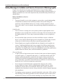
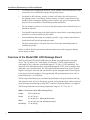
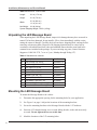
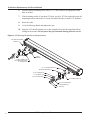
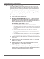
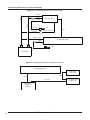
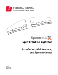
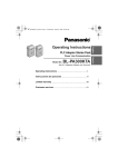
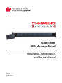
Model MB1
LED Message Board
Installation, Maintenance,
and Service Manual
25500112
Rev. A0 0215
Printed in U.S.A.
blank page
Installation, Maintenance, and Service Manual
Table of Contents
Safety Message to Installers and Service Personnel of Warning Lights........................................... 5
Overview of the Model MB1 LED Message Board................................................................................ 7
Unpacking the LED Message Board...................................................................................................... 8
Mounting the LED Message Board........................................................................................................ 8
Wiring the LED Message Board System in the Vehicle..................................................................... 10
Wiring the Standalone-Mount Message Board.............................................................................................10
Wiring the Message Board Control Head.....................................................................................................11
Safety Message to Operators of Warning Light Equipment.............................................................. 13
Operating the LED Message Board Controls...................................................................................... 14
Testing the Message Board System.................................................................................................... 14
Setting Configuration Options............................................................................................................. 15
Entering the Standard Menu.........................................................................................................................16
Entering the Security Menu..........................................................................................................................16
Exiting the Standard or Security Menu........................................................................................................16
Fleet Password and Security.........................................................................................................................16
Maintaining the Message Board........................................................................................................... 17
Replacing the Internal 15 A Fuse..................................................................................................................17
Getting Technical Support and Service............................................................................................... 18
Ordering Replacement Parts................................................................................................................ 18
Returning a Product to Federal Signal................................................................................................ 19
List of Tables
Table 1 Dimensions: Model MB1 Message Board............................................................................................7
Table 2 Dimensions: Control Head...................................................................................................................8
Table 3 Standalone kit contents........................................................................................................................8
List of Figures
Figure 1 LED Message Board with mounting hardware.................................................................................. 9
Figure 2 LED Message Board wired to control head..................................................................................... 12
Figure 3 Convergence Network connections with siren................................................................................ 12
Figure 4 Fuse location on PCB ..................................................................................................................... 18
3
LED Message Board System
© 2015 Federal Signal Corporation.
Printed in U.S.A.
PLASTITE® is a registered trademark of REMINC.
Installation, Maintenance, and Service Manual
Safety Message to Installers and Service Personnel of Warning Lights
People’s lives depend on your proper installation and servicing of Federal Signal
products. It is important to read and follow all instructions shipped with this product. In
addition, listed below are some other important safety instructions and precautions you
should follow:
Before Installation or Service
Qualifications
•
To properly install or service this equipment, you must have a good understanding
of automotive mechanical and electrical procedures and systems along with
proficiency in the installation and service of safety warning equipment. Always
refer to the vehicle’s service manuals when performing equipment installations on a
vehicle.
Light Hazards
•
To be an effective warning device, this product produces bright light that can be
hazardous to your eyesight when viewed at a close range. Do not stare directly into
this lighting product at a close range or permanent damage to your eyesight may
occur.
•
Do not install the light system in an area that would block, impair, or blind the
driver’s vision. Ensure that the light system is mounted in a position that is outside
of the driver’s field of vision, so the driver can safely operate the vehicle.
•
Federal Signal power supplies and light heads are designed to work together as a
system. Combining light heads and a power supply from different manufacturers
may reduce the warning effectiveness of the lighting system and may damage the
components. You should verify or test your combination to ensure the system works
together and meets federal, state, and local standards or guidelines.
Electrical Hazards
5
•
A light system is a high current system. In order for the system to function properly,
a separate negative (–) connection and positive (+) connection must be made. All
negative connections should be connected to the negative battery terminal and
a suitable fuse should be installed on the positive battery terminal connection as
close to the battery as possible. Ensure that all wires and fuses are rated correctly to
handle the device and system amperage requirements.
•
Never attempt to install aftermarket equipment that connects to the vehicle
wiring without reviewing a vehicle wiring diagram available from the vehicle
manufacturer. Ensure that your installation will not affect vehicle operation or
mandated safety functions or circuits. Always check the vehicle for proper operation
after installation.
•
The lighting system components, especially light bulbs, strobe tubes, LEDs, and the
outer housing, get hot during operation. Be sure to disconnect power to the system
and allow the system to cool down before handling any components of the system.
LED Message Board System
Installation, Maintenance, and Service Manual
•
Do not mount a radio antenna within 18 inches (45.7 cm) of the lighting system.
Placing the antenna too close to the lighting system could cause the lighting system
to malfunction or be damaged by strong radio fields. Mounting the antenna too
close to the lighting system may also cause the radio noise emitted from the lighting
system to interfere with the reception of the radio transmitter and reduce radio
reception.
•
Do not attempt to wash any unsealed electrical device while it is connected to its
power source.
During Installation and Service
• DO NOT get metal shavings inside the product. Metal shavings in the product
can cause the system to fail. If drilling must be done near the unit, place an ESDapproved cover over the unit. Inspect the unit after mounting to be sure there are no
shavings present in or near the unit.
•
DO NOT connect this system to the vehicle battery until ALL other electrical
connections are made, mounting of all components is complete, and you have
verified that no shorts exist. If the wiring is shorted to the vehicle body or frame,
high current conductors can cause hazardous sparks resulting in electrical fires or
flying molten metal.
•
DO NOT install equipment or route wiring (or the plug in cord) in the deployment
path of an airbag.
•
Before mounting any components, check the manual to be sure that the component
you are installing is suitable for use in that area of the vehicle. Many components
are not suitable for use in the engine compartment or other extreme environmental
exposure areas.
•
When drilling into a vehicle structure, be sure that both sides of the surface are clear
of anything that could be damaged. Remove all burrs from drilled holes. To prevent
electrical shorts, grommet all drilled holes through which wiring passes. Also,
ensure that the mounting screws do not cause electrical or mechanical damage to the
vehicle.
•
Refer to the manual packed with the lighting system for proper electrical
connections, additional precautions, and information.
•
Locate the light system controls so the VEHICLE and CONTROLS can be operated
safely under all driving conditions.
After Installation or Service
• After installation, test the light system to ensure that it is operating properly.
•
6
Test all vehicle functions, including horn operation, vehicle safety functions, and
vehicle light systems, to ensure proper operation. Ensure that the installation has not
affected the vehicle operation or changed any vehicle safety function or circuit.
LED Message Board System
Installation, Maintenance, and Service Manual
•
If a vehicle seat is temporarily removed, verify with the vehicle manufacturer if the
seat needs to be recalibrated for proper airbag deployment.
•
Scratched or dull reflectors, mirrors, or lenses will reduce the effectiveness of
the lighting system. Avoid heavy pressure and use of caustic or petroleum based
products when cleaning the lighting system. Replace any optical components that
may have been scratched or crazed during system installation.
•
Do not attempt to activate or de-activate the light system control while driving in a
hazardous situation.
•
You should frequently inspect the light system to ensure that it is operating properly
and that it is securely attached to the vehicle.
•
After installation and testing are complete, provide a copy of these instructions to
instructional staff and all operating personnel.
•
File these instructions in a safe place and refer to them when maintaining and/or reinstalling the product.
Failure to follow all safety precautions and instructions may result in property damage,
serious injury, or death.
Overview of the Model MB1 LED Message Board
The Federal Signal LED Model MB1 Message Board is a supplemental messaging
device. The 1.9 inch by 28.6 inch display is created by 772 blue, high brightness,
wide angle LEDs. It operates at a nominal input of 13.6 Vdc (11 Vdc minimum). The
functions of the Message Board are controlled through the CAT5 serial communication
cable and a special control head. The Message Board and control head use the Federal
Signal Convergence Network and can therefore operate alongside other Federal Signal
Convergence Network products. For programming and operating instructions, refer to
Federal Signal doc. no. 25500056.
The Message Board housing is coextruded polycarbonate with polycarbonate end caps
and elastomer seals. It has 30-foot power, ground, and communication cables connected
to the Message Board through a single IP67 connector. Mounting hardware is supplied.
The Message Board has an operating temperature range of –30 °C to +65 °C.
Table 1 Dimensions: Model MB1 Message Board
Length:
35.2 in (89.4 cm)
Height:
3.0 in (7.6 cm)
Width:
Net Weight:
7
3.3 in (8.4 cm) – Message Board body
4.8 in (12.2 cm) with standalone bracket
7.0 lb (3.2 kg)
LED Message Board System
Installation, Maintenance, and Service Manual
Table 2 Dimensions: Control Head
Length:
6.8 in (17.3 cm)
Height:
3.3 in (7.6 cm)
3.3 in (8.3 cm)
Width:
Net Weight:
1.6 in (4.1 cm)
0.8 lb (0.4 kg)
System Shipping Weight: 10.0 lb (4.5 kg)
Unpacking the LED Message Board
After unpacking the LED Message Board, inspect it for damage that may have occurred in
transit. If it has been damaged, do not install it. File a claim immediately with the carrier,
stating the extent of damage. Carefully check all envelopes, shipping labels, and tags before
removing or destroying them. Disposal of all shipping materials must be carried out in
accordance with national and local codes and standards Ensure that the parts listed in kit
contents list are included in the package. If you are missing any parts, contact Customer
Support at 1-800-264-3578, 7 a.m. to 5 p.m., Monday through Friday (CT).
Table 3 Standalone kit contents
Qty. Description
4
Bolt,Carriage,1/4"-20 SS
4
Nut, Keps,1/4"-20 SS
2
2
4
2
2
2
2
2
Bolt,Carriage, 3/8"-16 SS
Nut, 3/8-16, Hi-Corr. Resistant
Washer, Flat, 1/4", SS
Washer, Flat, 3/8", SS
Washer, Flat, 9/16", SS
Lockwasher, Split, 3/8", SS
Part Number
7004A020-12
7004A024-16
7058050
7059124
7072A024
7072A035
7072A140
7074A046
Bracket, Standalone Mt., Msg. Brd B 865200625
Screw, 8-32, Thread-Forming, Black 70000143-06
Mounting the LED Message Board
To mount the Message Board to the vehicle:
8
1.
Determine the appropriate spacing for the mounting holes for your application.
2.
See Figure 1 on page 9. Adjust the locations of the mounting brackets.
3.
Secure the mounting brackets to the Message Board with the 1/4" hardware.
4.
Start one 8-32 thread-forming screw in each sliding bracket, in the end most easily
accessed. Do not tighten the screws at this time.
5.
Mark the locations of the 3/8" mounting holes.
LED Message Board System
Installation, Maintenance, and Service Manual
6.
Drill the marked mounting holes with a 13/32" drill, and drill an appropriate cable
hole as needed.
7.
If the mounting surface is less than 1/8" thick, use the 9/16" flat washers between the
mounting brackets and surface. Loosely assemble both sides with the 3/8" hardware.
8.
Route the cable.
9.
Level the Message Board and tighten the nuts.
10. Snug the 8-32 thread-forming screws just enough to keep the Message Board from
sliding on the mounts. Do not pierce the polycarbonate housing with the screws.
Figure 1 LED Message Board with mounting hardware
8-32 THREAD-FORMING
SCREW (2)
CABLE
FERRITE
CABLE CONNECTOR
FROM MESSAGE BOARD
TO CONTROLLER
1/4" x 20 CARRIAGE BOLT (4)
MOUNTING BRACKET (2)
1/4" FLAT WASHER (4)
1/4"-20 KEPS NUT (4)
3/8" FLAT WASHER (2)
3/8" CARRIAGE BOLT (2)
9/16" FLAT WASHER (2)
3/8" LOCKWASHER (2)
3/8"-16 NUT (2)
290A7192C
9
LED Message Board System
Installation, Maintenance, and Service Manual
Wiring the LED Message Board System in the Vehicle
The LED Message Board is completely wired at the factory and does not require any
additional internal wiring. It has two 14 AWG power conductors (red and black) and a
connection for a Convergence Network communication cable. The conductors necessary
to control the Message Board are contained in the Convergence Network cable, which
connects to a compatible Federal Signal Message Board Control Head.
TWO-WAY RADIO ANTENNA LOCATION: The warning system and/or two-way radio
system may operate improperly if a two-way radio antenna is installed on or within
18 inches (47.5 cm) of the Message Board. Before permanently installing the Message
Board or a two-way radio antenna, test the warning system and two-way radio system.
DO NOT install a two-way radio antenna on the Message Board. Some installations
may require relocating the two-way radio antenna to a trunk or fender location.
LOCATING OPERATOR CONTROLS : Locate the light system controls so the VEHICLE
and CONTROLS can be operated safely under all driving conditions. Failure to observe
this warning could result in driver distraction or driver error while operating the vehicle.
BATTERY EXPLOSION : To avoid a battery explosion, always disconnect the negative
cable first and reconnect it last. Avoid causing a spark when connecting near or to the
battery. The gases produced by a battery can cause an electrical explosion that could
result in vehicle damage and serious injury.
REVERSE POLARITY / MISWIRING : Reverse polarity may damage the Message
Board and prevent operation. To avoid damage to the Message Board, ensure that the
battery voltage is the same as the voltage of the Message Board and that the correct
polarity is observed.
Wiring the Standalone-Mount Message Board
The Message Board draws approximately 50 mA in standby. To avoid excessive
battery drain, use an ignition-switch source for the Message Board only.
To wire the Standalone-Mount Message Board:
1. Ensure that the lines are adequately fused (see Figure 2 on page 12). Route the
Convergence Network cable from the Message Board into the cab or trunk of the
vehicle and to the planned location of the Message Board control head.
2. Route and connect the 14 AWG black lead to the ground (-NEG) terminal of the
vehicle battery.
3. Route and connect the 14 AWG red lead through a 20 A fuse at an appropriate
circuit in the vehicle that provides +12 V when ignition is activated.
10
LED Message Board System
Installation, Maintenance, and Service Manual
Wiring the Message Board Control Head
For the Message Board to operate properly, the power wires from the control head
must be wired directly to battery power and not to a switched power source. Failure
to do so may reduce the lifetime of its internal battery required to keep accurate time.
The control head also includes an IGN sense wire that, when disengaged, turns off the
control head after 15 seconds. If preferred, the control head includes an active-low
wire that activates the default message (Message One) when battery ground (-NEG) is
applied to it. For the wiring diagrams, see Figures 2 and 3 on page 12.
To wire the Message Board control head:
1. Ensure that the lines are adequately fused.
2. WITHOUT A FEDERAL SIGNAL SIREN: See Figure 2. If you are installing the
Message Board system without a Federal Signal Convergence Network siren,
insert the Convergence Network connector from the Message Board into one of
the two modular connectors in the back of the control head.
WITH A FEDERAL SIGNAL SIREN: See Figure 3.
a. If you are installing the system in a vehicle with a Federal Signal
Convergence Network siren, plug the Convergence Network connector from
the Message Board into one of the available modular connectors in the back
of the siren
b. Carefully route the included 25-foot CAT5 cable from another open
connection on the siren through the vehicle to where the control head will
be mounted.
c. Using the additional modular connector on the back of the Message Board
control head, plug in any additional Convergence Network control heads.
3. Route and connect the 22 AWG black lead to the ground (–NEG) terminal of the
vehicle battery.
4. Route and connect the 22 AWG red lead through a 5 A fuse at the source to the
positive (+BAT) terminal.
5. Route and connect the 22 AWG yellow lead to an appropriate circuit in the
vehicle that provides +12 V when ignition is activated.
6. OPTIONAL: For default message activation (message number one), route and
connect the 22 AWG brown lead through an installer-supplied switch with a
capacity of 100 mA to an appropriate circuit in the vehicle that provides battery
ground (-NEG) when default message activation is required.
11
LED Message Board System
Installation, Maintenance, and Service Manual
Figure 2 LED Message Board wired to control head
BLACK
22 AWG
RED
22 AWG
5A
22 AWG
YELLOW
22 AWG
14 AWG
CONTROL HEAD
+ IGN
100 mA DEFAULT MESSAGE
BLACK
LED MESSAGE BOARD
14 AWG
20 A
RED
+
−
CAT5
BROWN (OPTIONAL)
+ IGN
12 V BATTERY
290A7198D
Figure 3 Convergence Network connections with siren
LED MESSAGE BOARD
SMARTSIREN
CONTROLLER
CAT5
CAT5
25 ft CAT5
LED MESSAGE BOARD
CONTROL HEAD
SMARTSIREN
CONTROLLER
OR
PA300-CN
290A7199B
12
LED Message Board System
Installation, Maintenance, and Service Manual
Safety Message to Operators of Warning Light Equipment
People’s lives depend on your safe use of our products. Listed below are some
important safety instructions and precautions you should follow:
•
Do not attempt to activate or de-activate the light system control while driving in a
hazardous situation.
•
Although your warning system is operating properly, it may not be completely
effective. People may not see or heed your warning signal. You must recognize
this fact and continue driving cautiously.
•
Also, situations may occur which obstruct your warning signal when natural and
man-made objects are between your vehicle and others, such as raising your hood
or trunk lid. If these situations occur, be especially careful.
•
All effective sirens and horns produce loud sounds that may cause, in certain
situations, permanent hearing loss. You and your passengers should consider
taking appropriate safety precautions, such as wearing hearing protection.
•
In order to be an effective warning device, this product produces bright light that
can be hazardous to your eyesight when viewed at a close range. Do not stare
directly into this lighting product at a close range or permanent damage to your
eyesight may occur.
•
It is important that you fully understand how to safely operate this warning system
before use.
•
You should only operate your vehicle and its light/sound system in accordance
with your department’s Standard Operating Procedures.
•
If a selected function does not perform properly or if any of the lamps remain
illuminated when the control is off, disconnect the power connector from the control
unit and contact the nearest service center.
•
At the start of your shift, you should ensure that the entire warning light system
and the siren system is securely attached and operating properly.
•
Suction cup mounting is for temporary applications only. The unit should be
removed from the window and stored securely when not in use. Temperature
changes and sunlight can cause suction cups to lose holding power. Periodically
check the unit to be sure the suction cups have a firm grip on the mounting surface.
An improperly secured light could fall off of the vehicle causing injury and
damage.
•
The holding power of magnetic mounting systems is dependent upon surface
finish, surface flatness, and thickness of the steel mounting surface. Therefore, to
promote proper magnetic mounting:
✔
13
The mounting surface and magnets must be kept clean, dry, and free of
foreign particles that prevent good surface contact.
LED Message Board System
Installation, Maintenance, and Service Manual
✔
Ensure that mounting surface is flat.
✔
A magnet mounting system should not be used on vehicles with vinyl tops.
✔
To prevent sliding of light assembly on mounting surface, quick acceleration
and hard stops should be avoided.
Failure to follow these precautions may result in property damage, serious injury, or
death.
Operating the LED Message Board Controls
The Message Board is controlled entirely with the control head either through the
numeric keypad or by activating wires in the back of the control head. To activate a
message, use the numeric keypad to enter a message or use the arrow keys to scroll up or
down to select a message, then press ENT(ER). Alternatively, you can activate the default
message wire to turn on Message One, the default message.
Testing the Message Board System
LIGHT HAZARD :To be an effective warning device, an emergency warning system
produces bright light that can be hazardous to your eyesight when viewed at close
range. Do not stare directly into the lights at close range or permanent damage to
your eyesight may occur.
To test the Message Board system:
14
1.
Follow all the instructions in “Wiring the LED Message Board System in the
Vehicle” on page 10.
2.
Cycle IGN and verify that the control head powers up when IGN is activated and
turns off after 15 seconds when IGN is deactivated
3.
Activate a message by entering a message number through the numeric keypad and
press ENT. The LCD screen should display the activated message and the Message
Board should be displaying the message as well. If there is an error, the LCD screen
may notify you.
4.
OPTIONAL: Verify the default message (Message One) is activated when the default
5.
After the installation, check the entire system to be sure the lights are flashing
properly and all light system functions are operating properly.
message wire of the control head is activated.
LED Message Board System
Installation, Maintenance, and Service Manual
Setting Configuration Options
All Message Board settings and options are configured through various menus accessed
through the numeric keypad and LCD screen of the control head while it is operational.
There are two menus, Standard and Secure, that allow different information to be viewed
and configuration options that can be set. To prevent unwanted access and changes to the
system the Security Menu is only accessible by an numeric Fleet Password created by the
installer during installation of the Message Creation software. (For more information, see
“Fleet Password and Security” page 16).
You can navigate menus by using the up/down arrows or simply pressing the number
associated with that menu. If you do not press a key within 15 seconds, the menu times
out and returns to normal operation.
The Standard Menu has these menu items:
0. Adjust Keypad Backlight Level
1. Adjust LCD Contrast Level
2. View Date & Time
3. View Control Head Firmware Version
4. View Message Sign Firmware Version
5. Enter Security Menu
6. Update Messages via USB Flash Drive
7. Exit Standard Menu
The Security Menu has these menu items:
0. Change Date
1. Change Time
2. Adjust Message Board Intensity
3. Reset Fleet Password
4. Update Control Head Firmware
5. Exit Security Menu
15
LED Message Board System
Installation, Maintenance, and Service Manual
Entering the Standard Menu
To enter the Standard Menu:
1. Make sure that the control head is powered up and running.
2. Press and hold the ESC(APE) key for at least three seconds to enter the menu.
The control head beeps once you enter the Standard Menu and display the first
menu entry.
3. Use the up/down arrows or press the number associated with that menu to go the
menu item you want to view or change.
4. If you can change the menu item, use the keypad to enter your change, and press
ENT to confirm it.
Entering the Security Menu
To enter the Security Menu:
1. Put the control head in the Standard Menu as described in the previous section.
2. Use the up/down arrows or press the 5 to navigate to the Security Menu option
within the Standard Menu.
3. The display notifies you whether the Security Menu is locked or unlocked.
•
If unlocked, press ENT to enter the Security Menu.
•
If locked, the display prompts you to enter the numeric Fleet Password
created by the installer during installation of the Message Creation software.
You have three attempts to enter the Fleet Password correctly. Thr fourth attempt
lock the menu. battery power will need to cycled to the control pad to try again.
For more information on “Fleet Password and Security” below.
Exiting the Standard or Security Menu
To exit the Standard or Security Menu navigate the Exit Settings? Press ENT or wait
for 15 seconds for the keypad to exit the configuration menus.
Fleet Password and Security
The control head ships from the factory unlocked (i.e., no Fleet Password set) and
with a default message set. The control head uses a numeric fleet password to prevent
unauthorized message set downloads. When the Message Creation software is
installed, a numeric fleet password is created by the installer. The password is stored
into every message set created by the installation. If the control head is unlocked,
the first message set loaded transfers the numeric Fleet Password to the keypad. Any
subsequent message sets loaded need to match the Fleet Password from the original
file, otherwise the keypad will not accept the file. The Fleet Password is also used to
access the Security Menu to change configuration options.
16
LED Message Board System
Installation, Maintenance, and Service Manual
There are two ways to reset the Fleet Password:
If you know the Fleet Password
Navigate to the Security Menu (see page 16) and use the Reset Fleet Password menu
option.
If you do not know the Fleet Password
To unlock the control head:
1. Disconnect and apply +12 V (+BAT) on the yellow, blue, and orange wires.
2. Apply ground (-NEG) on the brown and black wires. Finally apply 12 V to the
red wire.
3. After a few seconds press ENT to confirm resetting the Fleet Password.
Maintaining the Message Board
Establishing a regular maintenance schedule for the LED Message Board extends its life
and ensures safety. Periodically check that the Message Board operates properly and that
all mounting hardware is securely fastened to the vehicle. Also, inspect the reflectors for
cracks, crazing (hairline cracks), discoloration, and other defects.
Replacing the Internal 15 A Fuse
The Message Board is protected with an internal 15 A blade fuse on the upper rear
corner of the driver-side PCBA (Figure 4 on page 18). To see if the fuse is bad, inspect
the horseshoe-shaped wire in it to see if it has burned through and broken the circuit.
STATIC SENSITIVE DEVICE: The circuitry of the Message Board can be damaged
by electrostatic discharge. Follow antistatic procedures while changing the fuse.
To replace the fuse:
1. Remove the four Phillips PLASTITE® screws from the driver-side end of the
Message Board.
2. Remove the two end caps.
3. To access the fuse, slide the aluminum carrier and PCBs out approximately two
inches.
4. Pull the fuse straight out to avoid damaging the connector.
5. Gently press a new fuse of the same type and amperage into the connector.
Ensure that all pins are properly seated.
6. Reassemble the Message Board. Use caution to prevent stripping the threads in the
polycarbonate housing.
17
LED Message Board System
Installation, Maintenance, and Service Manual
Figure 4 Fuse location on PCB
ALUMINUM CARRIER
DRIVER-SIDE END CAPS
15 A BLADE FUSE
ON PCB
PHILLIPS PLASTITE
SCREW (4)
290A7196B
Getting Technical Support and Service
For technical support and service, please contact:
Service Department
Federal Signal Corporation
Phone: 1-800-433-9132, 1-708-534-3400
Fax: 1-800-343-9706
Email: [email protected]
Ordering Replacement Parts
To order replacement parts, please contact your local dealer/distributor or:
Customer Support
Federal Signal Corporation
Phone: 1-800-264-3578, 1-708-534-3400
18
LED Message Board System
Installation, Maintenance, and Service Manual
Returning a Product to Federal Signal
Before returning a product to Federal Signal, call 800-264-3578, 800-433-9132, or 800824-0254 to obtain a Returned Merchandise Authorization number (RMA number). To
expedite the process, please be prepared with the following information:
•
Your Federal Signal customer or account number.
•
The purchase order number under which the items were purchased.
•
The shipping method.
•
The model or part number of the product being returned.
•
The quantity of products being returned.
•
Drop ship information as needed.
•
Any estimate required.
When you receive your RMA number:
•
Write the RMA number on the outside of the box of returned items.
•
Reference the RMA number on your paperwork inside of the box.
•
Write the RMA number down, so that you can easily check on status of the returned
equipment.
Send all material with the issued RMA Number to:
Federal Signal Corporation
2645 Federal Signal Drive
University Park, IL 60484-3167
Attn: Service Department
RMA: #__________
19
LED Message Board System
2645 Federal Signal Drive, University Park, IL 60486-3167
Tel.: (800) 264-3578 • (708-534-3400) • Fax: (800) 682-8022
www.fedsig.com