1
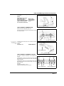
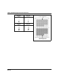
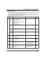
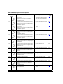
FUEL SYSTEM (Programmed Fuel Injection)
PGM-FI (Programmed Fuel Injection)
SYSTEM
SELF-DIAGNOSTIC PROCEDURE
Fit the safety lanyard clip to the base of the engine
stop switch.
WARNING LIGHT
If the warning light and PGM-FI malfunction indicator lamp (MIL) do not blink, the PGM-FI system has
no problem.
If the MIL and warning light blink, and the warning
buzzer sounds, the PGM-FI system has a problem.
MALFUNCTION INDICATOR
LAMP (MIL)
Push the SET, MODE, ID SET or ID NO. switch for
more than 2 seconds to stop the warning buzzer.
SET SWITCH
MODE SWITCH
Push the SET and MODE switches simultaneously
for more than 5 seconds to blink the failure code.
Read and record how many times the MIL and
warning light blinks and determine the cause of the
problem (page 8-13).
ID SET SWITCH
ID NO. SWITCH
To read the ECM memory of problem data, perform
the following:
JUMPER WIRE
Pull the safety lanyard clip off of the engine stop
switch.
Remove the seats (page 3-4).
Remove the dummy connector from the service
check connector.
Connect the service check connector terminals with
a jumper wire.
SERVICE CHECK
CONNECTOR
Fit the safety lanyard clip to the base of the engine
stop switch.
Push the SET and MODE switches simultaneously
for more than 5 seconds to blink the failure code.
WARNING LIGHT
If the ECM has no problem data in its memory, the
MIL and warning light will come on and stay on.
If the ECM has problem data in its memory, the MIL
and warning light will start blinking.
Read and record how many times the MIL and
warning light blink and determine the cause of the
problem (page 8-13).
MALFUNCTION INDICATOR
LAMP (MIL)
8-9
FUEL SYSTEM (Programmed Fuel Injection)
SELF-DIAGNOSTIC MEMORY RESET
PROCEDURE
1. Remove the seats (page 3-4).
2. Connect the service check connector terminals
using a jumper wire.
3. Fit the safety lanyard clip to the base of the
engine stop switch
4. Remove the jumper wire from the service check
connector.
5. The MIL and warning light lights about 5 seconds.
While the MIL and warning light lights, connect
the service check connector terminal again with
the jumper wire
The self-diagnostic memory is erased, if the MIL
and warning light goes off and starts blinking.
• The service check connector must be jumped
while the MIL and warning light lights. If not, the
MIL and warning light will not start blinking.
• Note that the self-diagnostic memory cannot be
erased if you turn off the engine stop switch
before the MIL and warning light starts blinking.
JUMPER WIRE
SERVICE CHECK
CONNECTOR
WARNING LIGHT
If the MIL and warning light blinks 33 times, the
diagnostic memory has not been erased.
MALFUNCTION INDICATOR
LAMP (MIL)
PEAK VOLTAGE INSPECTION
PROCEDURE
• Use this procedure for the ignition pulse generator and cam pulse generator inspection.
• Check cylinder compression and check that all
the spark plugs are installed correctly.
• Use a commercially available digital multimeter
with an impedance of 10 MΩ/DCV minimum.
• The display value differs depending upon the
internal impedance of the multimeter.
Remove the storage box (page 3-8).
Disconnect the fuel pump 5P gray connector.
8-10
FUEL PUMP 5P GRAY CONNECTOR
FUEL SYSTEM (Programmed Fuel Injection)
Connect the peak voltage adaptor to the digital
multimeter.
TOOLS:
IgnitionMate peak voltage
tester (U.S.A. only) or
Peak voltage adaptor
with commercially available
digital multimeter (impedance 10 MΩ/DCV minimum)
DIGITAL MULTIMETER
MTP–08–0193
07HGJ–0020100
(not available in
U.S.A.)
PEAK VOLTAGE ADAPTOR
TEST HARNESS CONNECTION
Remove the left side panel (page 3-5).
Disconnect the ECM 22P gray and 22P black connectors from the ECM.
22P BLACK CONNECTOR
22P GRAY CONNECTOR
ECM
Do not disconnect
the 6P black connector from the
ECM.
Connect the test harnesses set to the ECM and ECM
connectors.
TOOLS:
Test harness set
07WMZ-MBGA000
TEST HARNESS SET
ECM
TEST HARNESS TERMINAL LAYOUT
The ECM connector terminals are numbered as
shown.
B1
B11
C1
C11
B12
B22
C12
C22
Terminals No. 1 to No. 22 of the test pin box of the
test harness are for terminals C1 to C22 of the ECM
black connector.
Terminals No. 31 to No. 52 of the test pin box of the
test harness are for terminals B1 to B22 of the ECM
gray connector.
Example:
ECM terminals: B8 (+) – C8 (–)
Test pin box terminals: No. 38 – No. 8
GRAY CONNECTOR
BLACK CONNECTOR
8-11
FUEL SYSTEM (Programmed Fuel Injection)
Terminal conversion chart:
22P black connector
terminal No.
C1
C2
Test pin box
terminal No.
1
2
C21
C22
22P gray connector
terminal No.
B1
B2
21
22
Test pin box
terminal No.
1
2
B21
B22
21
22
TERMINALS FOR 22P
BLACK CONNECTOR
TERMINALS FOR 22P
GRAY CONNECTOR
8-12
FUEL SYSTEM (Programmed Fuel Injection)
PGM-FI SELF-DIAGNOSIS MALFUNCTION INDICATOR LAMP (MIL)
FAILURE CODES
• The PGM-FI malfunction indicator lamp (MIL) denotes the failure codes (the number of blinks from 0 to 47). The MIL has
two types of blinks, a long blink and short blink. The long blink lasts for 1.3 seconds, the short blink lasts for 0.5 seconds. When two long blinks occur, and five short blinks, that problem code is 25 (two long blinks = 20 blinks, five short
blinks = 5 blinks). Then, go to the flow chart and see problem code 25.
• When the Engine Control Module (ECM) stores some failure codes, the MIL shows the failure codes in the order from
the lowest number to highest number. For example, when the MIL blinks once, then blinks seven times, two failures
have occurred. Follow the flow chart for failure codes 1 and 7.
Number of
PGM-FI MIL
blinks
0
No
blinks
Causes
Symptoms
Refer to
page
• Open circuit at the power input and
ground wires of the ECM
• Blown sub-fuse D (7.5 A)
• Faulty main relay
• Open circuit in the main relay related circuits
• Faulty engine stop switch
• Open circuit in the engine stop switch
related circuits
• Faulty ECM
• Blown main fuse (30 A)
• Open circuit in the MIL wire
• Faulty ECM
• Engine does not start
–
• Engine operates normally
–
• Short circuit in the MIL wire
• Faulty ECM
• Engine operates normally
–
• Short circuit in the service check connector
wire
• Engine operates normally
–
• Loose or poorly connected MAP sensor
connector
• Open or short circuit in the MAP sensor
wire
• Faulty MAP sensor
• Engine operates normally
8-16
• Loose or poor connection of the MAP sensor vacuum hose
• Faulty MAP sensor
• Engine operates normally
8-19
• Loose or poorly connected ECT sensor
connector
• Open or short circuit in the ECT sensor
wire
• Faulty ECT sensor
• Hard to start at low temperatures (ECM controls using
preset value; Cooling water
temperature: 90°C/194°F)
• Engine operates below 3,000
rpm
• Poor engine response when
operating the throttle quickly
(ECM controls using preset
value; Throttle opening: 0°)
8-20
No
blinks
Blinking
Stay lit
1
Blink
2
Blinks
7
Blinks
8
• Loose or poorly connected TP sensor connector
• Open or short circuit in the TP sensor wire
• Faulty TP sensor
8-22
Blinks
8-13
FUEL SYSTEM (Programmed Fuel Injection)
Number of
PGM-FI MIL
blinks
9
Causes
Symptoms
Refer to
page
• Engine operates below 3,000
rpm (ECM controls using preset value; Intake air temperature: 25°C/77°F)
8-24
Blinks
• Loose or poorly connected IAT sensor
connector
• Open or short circuit in the IAT sensor
wire
• Faulty IAT sensor
• Engine operates below 3,000
rpm
8-27
Blinks
• Loose or poorly connected No. 1 injector
connector
• Open or short circuit in the No. 1 injector
wire
• Faulty No. 1 injector
• Engine operates below 3,000
rpm
8-29
Blinks
• Loose or poorly connected No. 2 injector
connector
• Open or short circuit in the No. 2 injector
wire
• Faulty No. 2 injector
• Engine operates below 3,000
rpm
8-31
Blinks
• Loose or poorly connected No. 3 injector
connector
• Open or short circuit in the No. 3 injector
wire
• Faulty No. 3 injector
• Engine operates below 3,000
rpm
8-33
Blinks
• Loose or poorly connected No. 4 injector
connector
• Open or short circuit in the No. 4 injector
wire
• Faulty No. 4 injector
• Engine does not start
8-35
Blinks
• Loose or poorly connected cam pulse generator connector
• Open or short circuit in the cam pulse generator wire
• Faulty cam pulse generator
• Engine does not start
8-36
Blinks
• Loose or poorly connected ignition pulse
generator connector
• Open or short circuit in the ignition pulse
generator wire
• Faulty ignition pulse generator
• Engine operates below 3,000
rpm
8-38
Blinks
• Loose or poorly connected knock sensor
connector
• Open or short circuit in the knock sensor
wire
• Faulty knock sensor
• Loose or poorly connected IAC valve connector
• Open or short circuit in the IAC valve wire
• Faulty IAC valve
• Engine stalls, hard to start,
rough idling
8-39
• Faulty E2-PROM in the ECM
• Engine operates normally
• Does not hold the self-diagnostic data
8-41
• Loose or poorly connected TCP sensor
connector
• Open or short circuit in the TCP sensor
wire
• Faulty TCP sensor
• Engine operates below 3,000
rpm
8-42
• Loose or poor connection of the TCP sensor pressure hose
• Faulty TCP sensor
• Engine operates below 3,000
rpm
8-44
12
13
14
15
18
19
25
29
Blinks
33
Blinks
42
Blinks
43
Blinks
8-14
FUEL SYSTEM (Programmed Fuel Injection)
Number of
PGM-FI MIL
blinks
44
Blinks
45
Blinks
46
Blinks
47
Blinks
Refer to
page
Causes
Symptoms
• Loose or poorly connected engine oil temperature sensor connector
• Open or short circuit in the engine oil temperature sensor wire
• Faulty engine oil temperature sensor
• Hard to start at low temperatures (ECM controls using
preset value; Engine oil temperature: 90°C/194°F)
• Engine operates below 3,000
rpm
• Engine operates below 3,000
rpm
8-45
• Engine does not start
8-49
• Engine operates below 3,000
rpm when the coolant temperature is 85 – 95°C (185 –
203°F)
• Engine does not start when
the coolant temperature is
above 95°C (203°F)
8-50
• Loose or poorly connected wastegate control solenoid valve connector
• Open or short circuit in the wastegate control solenoid valve wire
• Faulty wastegate control solenoid valve
• Loose or poor connection of the wastegate
control solenoid valve hose
• Clogged wastegate actuator pressure
hose
• Faulty wastegate actuator
• Faulty TCP sensor
• Faulty cooling system
• Loose or poorly connected MST switch
connector
• Open or short circuit in the MST switch
wire
• Faulty MST switch
• Faulty cooling system
• Loose or poorly connected ECT sensor
connector
• Open or short circuit in the ECT sensor
wire
• Faulty ECT sensor
8-46
8-15