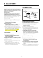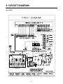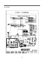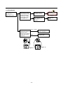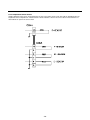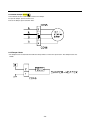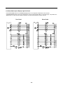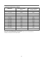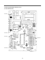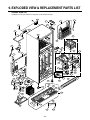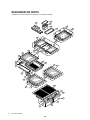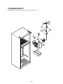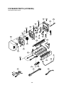
1
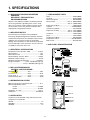
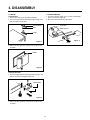
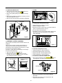
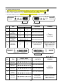
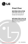
REFRIGERATOR
SERVICE MANUAL
CAUTION
BEFORE SERVICING THE UNIT,
READ THE SAFETY PRECAUTIONS IN THIS MANUAL.
models
LRTN22330**
LRTN19330**
LRTN22320**
LRTN19320**
CONTENTS
SAFETY PRECAUTIONS ....................................................................................................................................................... 2
SPECIFICATIONS................................................................................................................................................................... 3
PARTS IDENTIFICATION ....................................................................................................................................................... 4
DISASSEMBLY.................................................................................................................................................................... 5-6
DOOR................................................................................................................................................................................... 5
DOOR SWITCH.................................................................................................................................................................... 5
FAN AND FAN MOTOR........................................................................................................................................................ 6
DEFROST CONTROL ASSEMBLY...................................................................................................................................... 6
LAMP.................................................................................................................................................................................... 6
CONTROL BOX-REFRIGERATOR ...................................................................................................................................... 6
ADJUSTMENT..................................................................................................................................................................... 7-8
COMPRESSOR.................................................................................................................................................................... 7
PTC-STARTER..................................................................................................................................................................... 7
OLP (OVERLOAD PROTECTOR) ....................................................................................................................................... 8
TO REMOVE THE COVER PTC ...........................................................................................................................................8
CIRCUIT DIAGRAM .......................................................................................................................................................... 9-10
TROUBLESHOOTING..................................................................................................................................................... 11-16
COMPRESSOR AND ELECTRICAL COMPONENTS ....................................................................................................... 11
PTC AND OLP.................................................................................................................................................................... 12
OTHER ELECTRICAL COMPONENTS ............................................................................................................................. 13
SERVICE DIAGNOSIS CHART.......................................................................................................................................... 14
REFRIGERATION CYCLE ............................................................................................................................................ 15-16
OPERATION PRINCIPLE & REPAIR METHOD OF ICEMAKER .................................................................................. 17-20
DESCRIPTION OF FUNCTION & CIRCUIT OF MICOM ............................................................................................... 21-33
EXPLODED VIEW & REPLACEMENT PARTS LIST ..................................................................................................... 34-39
SAFETY PRECAUTIONS
Please read the following instructions before servicing your
refrigerator.
1. Check the refrigerator for electrical faults.
7. Close the top door before opening the bottom door.
Otherwise, you might hit your head when you stand up.
2. To prevent electric shock, unplug before servicing.
8. When tilting the refrigerator, remove any materials on
the refrigerator, especially the glass shelves and stored
food.
3. Always check line voltage and amperage.
4. Use standard electrical components or cause your skin
to freeze and stick to the surfaces inside the freezer.
9. When servicing the evaporator, wear cotton gloves.
This is to prevent injuries from the sharp evaporator
fins.
5. Don't touch metal products in the freezer with wet
hands. This may cause frostbite.
6. Prevent water from spiling onto electric elements or the
machine parts.
10. Service on the refrigerator should be performed by a
qualified technician. Sealed system repair must be
performed by a CFC certified technician.
-2-
1. SPECIFICATIONS
1-1 DISCONNECT POWER CORD BEFORE
SERVICING
IMPORTANT – RECONNECT ALL
GROUNDING DEVICES
1-7 REPLACEMENT PARTS
Relay ............................................................. 6748C-0004D
Overload ....................................................... 6750C-0004S
Defrost Thermostat ...................................... 6615JB2005B
Defrost Heater .............................. 19cu. ft : 5300JK1003D
............................... 22cu. ft : 5300JK1003J
Evaporator Fan Motor .................................. 4681JB1016J
Capacitor ................................................... OCZZJB2003H
Compressor (Hi-Side) .................................. 2521C-A62A8
Evaporator (Lo-Side) ..................... 19cu. ft : 5421JJ0003A
..................... 22cu. ft : 5421JJ0002A
Condenser .................................................... 5403JJ1003A
Dryer ............................................................. 5851JJ2002K
Condenser Fan Motor .................................. 4681JK1001B
Temperature Control ................................. 6871JB2043A,B
Main Control.................................................. 6871JB1185A
All parts of this appliance capable of conducting electrical
current are grounded. If grounding wires, screws, straps,
clips, nuts or washers used to complete a path to ground
are removed for service, they must be returned to their
original position and properly fastened.
1-2 IMPORTANT NOTICE
This information is intended for use by individuals
possessing adequate backgrounds of electrical, electronic
and mechanical experience. Any attempt to repair a major
appliance may result in personal injury and property
damage. The manufacturer or seller cannot be responsible
for the interpretation of this information, nor can it assume
any liability in connection with its use.
1-8 AIR FLOW / CIRCULATION D’AIR
1-3 ELECTRICAL SPECIFICATIONS
Temperature Control (Position : MID) .................... 8-(-6)°F
Defrost Control .......................................................... 7 hrs.
Defrost Thermostat ..................................................... 50°F
Electrical Rating :115V. AC, 60 Hz. ...................... 1-5 Amp.
Maximum Current Leakage ..................................... 0.5 mA
Maximum Ground Path Resistance .................. 0.14 Ohms
Energy Consumption ............... 19 cu.ft : 443 kWh/yr(Energy star)
....................................... 22 cu.ft : 468 kWh/yr(Energy star)
EVAPORATOR/
EVAPORATEUR
1-4 NO LOAD PERFORMANCE
CONTROL POSITION: MID/MID
And Ambient of : .........................70°F ..........................90°F
Fresh Food, °F ...........................33-41 ...................... 33-41
Frozen Food, °F .........................(-4)-4....................... (-4)-4
Percent Running Time ...............25-35 ...................... 45-60
1-5 REFRIGERATION SYSTEM
Minimum Compressor Capacity Vacuum ................... 21 in.
Minimum Equalized Pressure
@ 70°F ....................................................... 49 PSIG
@ 90°F ....................................................... 56 PSIG
Refrigerant - R - 134a ............................................ 5.47 oz.
Compressor ..................................................... 649 BTU/hr
FREEZER
CONTROL
EVAPORATOR
COLD AIR
1-6 INSTALLATION
MIXED AIR
Clearance must be provided at top, sides and rear of the
refrigerator for air circulation.
AT TOP ......................................................................... 1 in
AT SIDES ................................................................... 1/8 in
AT REAR ...................................................................... 1 in
FRESH FOOD
AIR RETURN TO
EVAPORATOR
-3-
2. PARTS IDENTIFICATION
Pizza Nook*
Leveling Screw (inside)
CustomCube Ice maker *
Refrigerator Door Bin
CustomFit
Egg Box*
FlexiFloor *
Design-A-Door
Digital Sensor Control
Icebeam Door Cooling *
Refrigerator Light *
Door Cooling
Chef Fresh * / Snack Pan
Dairy Bin
Shelves
Freezer Door Bin *
Can Dispenser*
Freezer Light
OptiBin Crisper
* on some models
Base Grille
-4-
3. DISASSEMBLY
3-1 DOOR
3-2 DOOR SWITCH
● Freezer
1. To remove the door switch, pry it out with a slotted-type
driver, as shown in (Figure 4).
2. Disconnect the lead wire from the switch.
Door
1. Remove the hinge cover by pulling it upwards.
2. Loosen hexagonal bolts attaching the upper hinge to the
body and lift the freezer door.
HINGE COVER
LEAD WIRE
BOLT
DOOR SWITCH
HINGE
Figure 4
Figure 1
3. Pull out the door gasket to remove from the door foam
assembly.
GASKET
Figure 2
●
Refrigerator Door
1. Loosen hexagonal bolts attaching the lower hinge to the
body to remove the refrigerator door only.
LOWER HINGE
BOLT
Figure 3
2. Pull out the door gasket to remove from the door foam
assembly.
-5-
3-3 FAN AND FAN MOTOR
3-5 LAMP
1. Remove the freezer shelf. (If your refrigerator has an
icemaker, remove the icemaker first)
2. Remove the grille by pulling it out and by loosening a
screw.
3. Remove the Fan Motor assembly by loosening 4 screws
and disassemble the shroud.
4. Pull out the fan and separate the Fan Motor and Bracket.
Figure 8
FAN MOTOR
SHROUD
3-5-1 Refrigerator Compartment Lamp
1. Unplug the power cord from the outlet.
2. Remove refrigerator shelves.
3. Release the hooks on both ends of the lamp shield and
pull the shield downward to remove it.
4. Turn the lamp counterclockwise.
5. Assemble in reverse order of disassembly. Replacement
bulb must be the same specification as the original
(Max. 60 W-2EA).
BRACKET
FAN
GRILLE
Figure 5
3-4 DEFROST CONTROL ASSEMBLY
Defrost Control assembly consists of Defrost Sensor and
FUSE–M.
Defrost sensor functions to defrost automatically. It is
attached to metal side of the Evaporator and senses
Temperature. At the temperature of 162°F(72°C), it stops
the emission of heat from the Heater.
Fuse-M is a safety device for preventing over-heating of
the Heater when defrosting.
1. Pull out the grille assembly. (Figure 6)
2. Separate the connector with the Defrost Control
assembly and replace the Defrost Control assembly
after cutting the Tie Wrap. (Figure 7)
GRILLE ASSEMBLY
Figure 9
3-5-2 Freezer Compartment Lamp
1. Unplug refrigerator or disconnect power.
2. Reach behind light shield to remove bulb.
3. Replace bulb with a 40-watt appliance bulb.
4. Plug in refrigerator or reconnect power.
3-6 CONTROL BOX-REFRIGERATOR
1. First, remove all shelves in the refrigerator, than remove
the Refrigerator Control Box by loosening 2 screws.
DEFROST-CONTROL
ASSEMBLY
CONTROL BOX
Figure 6
Figure 7
COVER LAMP
Figure 10
2. Remove the Refrigerator Control Box by pulling it
downward.
3. Disconnect the lead wire on the right position and
separate the lamp sockets.
-6-
4. ADJUSTMENT
4-2-3 PTC-Applied Circuit Diagram
Method for the Motor
4-1 COMPRESSOR
● Starting
4-1-1 Role
The compressor intakes low temperature and low pressure
gas from the evaporator of the refrigerator and compresses
this gas to high-temperature and high-pressure gas. It then
delivers the gas to the condenser.
OVERLOAD PROTECTOR
N
4-1-2 Composition
The compressor includes overload protection. The PTC
starter and OLP (overload protector) are attached to the
outside of the compressor. Since the compressor is
manufactured to tolerances of 1 micron and is hermetically
sealed in a dust and moisture-free environment, use
extreme caution when repairing it.
C
PTC
2
5
S
L1
3
6
PTC STARTER
4-1-3 Note for Usage
(1) Be careful not to allow over-voltage and over-current.
(2) If compressor is dropped or handled carelessly, poor
operation and noise may result.
(3) Use proper electric components appropriate to the
Particular Compressor in your product.
(4) Keep Compressor dry.
If Compressor gets wet (in the rain or a damp
environment) and rust forms in the pin of the Hermetic
Terminal, poor operation and contact may result.
(5) When replacing the Compressor, be careful that dust,
humidity, and soldering flux don’t contaminate the inside
of the compressor. Dust, humidity, and solder flux
contaminate the cylinder and may cause noise or
improper operation even cause it to lock up.
COMPRESSOR
MOTOR
M
M
S
SEALED
TERMINAL
RSCR
Figure 11
4-2-4 Motor Restarting and PTC Cooling
(1) It requires approximately 5 minutes for the pressure to
equalize before the compressor can start.
(2) The PTC device generates heat during operation.
Therefore, it must be allowed to cool before the
compressor can restart.
4-2-5 Relation of PTC-Starter and OLP
(1) If the compressor attempts to restart before the PTC
device is cooled, the PTC device will allow current to
flow only to the main winding.
(2) The OLP will open because of the over current
condition. This same process will continue (3 to 5
times) when the compressor attempts to restart until
the PTC device has cooled. The correct OLP must be
properly attached to prevent damage to the
compressor.
4-2 PTC-STARTER
4-2-1 Composition of PTC-Starter
(1) PTC (Positive Temperature Coefficient) is a no-contact
semiconductor starting device which uses ceramic
material consisting of BaTiO3.
(2) The higher the temperature is, the higher the resistance
value. These features are used as a starting device for
the Motor.
4-2-6 Note for Using the PTC-Starter
(1) Be careful not to allow over-voltage and over-current.
(2) Do not drop or handle carelessly.
(3) Keep away from any liquid.
If liquid such as oil or water enters the PTC,
PTC materials may fail due to breakdown of their
insulating capabilities.
(4) If the exterior of the PTC is damaged, the resistance
value may be altered. This can cause damage to the
compressor and result in a no-start or hard-to-start
condition.
(5) Always use the PTC designed for the compressor and
make sure it is properly attached to the compressor.
4-2-2 Role of PTC-Starter
(1) The PTC is attached to the Sealed Compressor and is
used for starting the Motor.
(2) The compressor is a single-phase induction motor.
Durign the starting operation, the PTC allows current
flow to both the start winding and main winding.
-7-
4-3 OLP (OVERLOAD PROTECTOR)
4-4 TO REMOVE THE COVER PTC
4-3-1 Definition of OLP
(1) OLP (OVERLOAD PROTECTOR) is attached to the
Compressor and protects the Motor by opening the
circuit to the Motor if the temperature rises and
activating the bimetal spring in the OLP.
(2) When high current flows to the Compressor motor, the
Bimetal works by heating the heater inside the OLP,
and the OLP protects the Motor by cutting off the
current flowing to the Compressor Motor.
4-3-2 Role of the OLP
(1) The OLP is attached to the Sealed Compressor used
for the Refrigerator. It prevents the Motor Coil from
being started in the Compressor.
(2) For normal operation of the OLP, do not turn the Adjust
Screw of the OLP in any way.
1) Remove the Cover Back M/C.
(2) Remove the screw on Cover PTC.
(OVERLOAD PROTECTOR cross section)
12345678
330 FBYY
Electrical
characteristics
part number
-S1 BOX98
Customer part
number
Lot code/
date code
Physical
termination
part number
Part
No.
Name
Base, phenolic
(UL 94 V-0 rated)
Movable arm support, plated steel
Stationary contact support,
plated steel
Heater support, plated steel
Heater, resistance alloy
Disc, thermostatic alloy
Movable arm, spring temper
copper alloy
Contact, movable, silver on copper
Contact, stationary, silver on copper
Slug, plated steel
Cover, polyester
(UL 94 V -0 rated)
Pin connector, plated copper alloy
(To engage 2.33/2.66 mm dia. pin)
Quick-connect terminal, brass,
conforms to UL 310, MEMA
DC-2, DIN 46344
1
(3) Remove two Housings on upper part of Cover PTC.
Figure 12
(4) Take out the cover PTC from upper to lower position
like .
2
(5) Turn 45° in the direction of and take it out.
(6) Assembly in reverse order of disassembly.
-8-
5. CIRCUIT DIAGRAM
BEST MODEL
-9-
BETTER MODEL
- 10 -
6. TROUBLESHOOTING
6-1 COMPRESSOR AND ELECTRIC COMPONENTS
1
Power Source.
Remove PTC-Starter
from Compressor and
measure voltage
between Terminal C of
Compressor and
Terminals 5 or 6 of PTC.
(Reated Voltage
±10%)?
No Voltage.
OLP disconnected?
YES
2
YES
Replace OLP.
5
Check connection
condition.
Reconnect.
Applied voltage isn't
in range of Rating
Voltage ±10%.
Check
resistance of
Motor
Compressor.
Check resistance
between M-C, S-C and
M-S in Motor
Compressor.
Check
resistance of
PTC-Starter.
Check resistance of
two terminals in
PTC-Starter.
4
Check OLP.
Check resistance of
two terminals in OLP.
5
Check
starting state.
2
3
Advise customer that
power supply needs to be
checked by an electrician.
5
Readings OK
Open or short
3
Replace
Compressor.
3
4
Readings OK
5
4
Replace
PTC-Starter.
Open or short
5
Readings OK
Check the power supply
under load.
(Compressor attempting
to re-start after being off
for 5 minutes).
5
Open or short
Supply
voltage
rating with
±10%.
YES
Replace OLP.
YES
Did
compressor
start?
NO
NO
- 11 -
Compressor
is OK
Replace the
compressor
1
6-2 PTC AND OLP
Separate PTC-Starter
from Compressor and
measure resistance
between No. 5 and 6
of PTC-Starter with a
Tester.(Figure 13)
Observation value is
115V/60Hz : 6.8Ω±30%
Check another
electric component.
The resistance value
is 0Ω (short) or
∞ (open).
Replace PTCStarter
Shows continuity
Separate OLP from
Compressor and check
resistance value
between two terminals
Open
of OLP with a Tester.
(Figure 14)
Check another
electric component.
Replace OLP.
5
6
Normal operation of
Compressor is
impossible or poor.
Figure 13
- 12 -
Figure 14
6-3 OTHER ELECTRIC COMPONENTS
▼ Not cooling at all
Compressor
doesn't run.
Check for open short or
incorrect resistance readings
in the following components
Cause
a. Starting devices
Short, open or broken.
b. OLP
Poor contact
or shorted.
c. Compressor coil
Coil open or shorted.
d. Wiring harness
Poor contact
or shorted.
Replace
indicated component.
▼ Poor cooling performance
Compressor runs
poorly.
Fan motor
doesn't run.
Check a starting
voltage.
Low voltage.
Raise voltage.
Check voltage at
starting devices.
Poor or broken or
open contact.
Replace
indicated component.
Check current at
Compressor.
Shorted.
Check rating of OLP.
Lack of capacity.
Check wiring circuit.
Wire is open or
shorted.
Replace
indicated component.
Coil is shorted or
open.
Check Fan Motor.
Heavy frost buildup on
EVAPORATOR.
Check current flow in
the following
components:
sensor
Fuse-M
Check current flow in
the Defrost Heater.
- 13 -
Open.
Replace
indicated component.
Open.
Replace
Defrost Heater.
6-4 SERVICE DIAGNOSIS CHART
COMPLAINT
POINTS TO BE CHECKED
REMEDY
No Cooling.
• Is the power cord unplugged from the outlet?
• Check if the power Switch is set to OFF.
• Check if the fuse of the power Switch is shorted.
• Measure the voltage of the power outlet.
• Plug into the outlet.
• Set the switch to ON.
• Replace the fuse.
• If the voltage is low, correct the wiring.
Cools poorly.
• Check if the unit is placed too close to the wall.
• Check if the unit is placed too close to the stove,
gas cooker, or in direct sunlight.
• Is the ambient temperature too high or
the room door closed?
• Check if food put in the refrigerator is hot.
• Did you open the door of the unit too often
or check if the door is sealed properly?
• Check if the Control is set to Warm position.
• Place the unit about 10 cm from the wall.
• Place the unit away from these heat sources.
Foods in the
Refrigerator
are frozen.
• Is food placed in the cooling air outlet?
• Check if the control is set to colder-position.
• Is the ambient temperature below 41°F(5°C)?
• Place foods in the high-temperature section.
(front part)
• Set the control to Recommended-position.
• Set the control to Warm-position.
Condensation or ice
forms inside
the unit.
• Is liquid food sealed?
• Check if food put in the refrigerator is hot.
• Did you open the door of the unit too
often or check if the door is sealed properly?
• Seal liquid foods with wrap.
• Put in foods after they have cooled down.
• Don't open the door too often and close
it firmly.
Condensation forms
in the Exterior Case.
• Check if the ambient temperature and humidity
of the surrounding air are high.
• Is there a gap in the door gasket?
• Wipe moisture with a dry cloth. It will disappear
in low temperature and humidity.
• Fill up the gap.
There is abnormal
noise.
• Is the unit positioned in a firm and even place?
• Adjust the Leveling Screw, and position
in a firm place.
• Remove the objects.
• Are any unnecessary objects placed
in the back side of the unit?
• Check if the Drip Tray is not firmly fixed.
• Check if the cover of the compressor enclosure
in the lower front side is taken out.
Door does not
close well.
• Check if the door gasket is dirty with
an item like juice.
• Is the refrigerator level?
●
• Put in foods after they have cooled down.
• Don't open the door too often and close
it firmly.
• Set the control to Recommended-position.
• Fix the Drip Tray firmly in the original position.
• Place the cover in its original position.
• Clean the door gasket.
• Is there too much food in the refrigerator?
Ice and foods
smell unpleasant
• Lower the ambient temperature.
• Check if the inside of the unit is dirty.
• Are foods with a strong odor unwrapped?
• The unit smells of plastic.
• Position in the firm place and level the
Leveling Screw.
• Make sure food stored in shelves does not prevent
the door from closing.
• Clean the inside of the unit.
• Wrap foods that have a strong odor.
• New products smell of plastic, but this
will go away after 1-2 weeks.
Other possible problems:
Check if frost forms in
the freezer.
Not
defrosting.
Check Components
of the defrosting
circuit.
Check the
refrigeration system.
The system
is faulty.
Perform sealed
system repair.
Check the
Thermistor.
The operation of
the Thermistor is
incorrect.
- 14 -
Replace the
Thermistor.
6-5 REFRIGERATING CYCLE
▼ Troubleshooting Chart
STATE OF
THE UNIT
CAUSE
STATE OF THE
EVAPORATOR
TEMPERATURE
OF THE
COMPRESSOR
REMARKS
LEAKAGE
RESTRICTED BY DUST
PARTIAL
LEAKAGE
Freezer
compartment and
Refrigerator don't
cool normally.
Low flowing sound of
Refrigerant is heard and
frost forms in inlet only.
A little higher
than ambient
temperature.
• Refrigerant level is low due
• to a leak.
• Normal cooling is possible by
• restoring the normal amount of
• refrigerant and repairing the leak.
COMPLETE
LEAKAGE
Freezer
compartment and
Refrigerator don't
cool normally.
Flowing sound of refrigerant
is not heard and frost isn't
formed.
Equal to ambient
temperature.
• No discharging of Refrigerant.
• Normal cooling is possible by
• restoring the normal amount of
• refrigerant and repairing the leak.
PARTIAL
RESTRICTION
Freezer
compartment and
Refrigerator don't
cool normally.
Flowing sound of refrigerant
is heard and frost forms
in inlet only.
A little higher
than ambient
temperature.
• Normal discharging of the
• refrigerant.
• The capillary tube is faulty.
WHOLE
RESTRICTION
Freezer
Flowing sound of refrigerant
compartment and
is not heard and frost isn't
Refrigerator don't cool. formed.
Equal to ambient
temperature.
• Normal discharging of the
• Refrigerant.
Cooling operation
stops periodically.
Flowing sound of refrigerant
is not heard and frost melts.
Lower than
ambient
temperature.
• Cooling operation restarts
• when heating the inlet of the
• capillary tube.
COMPRESSION
Freezer and
Refrigerator
don't cool.
Low flowing sound of
refrigerant is heard and
frost forms in inlet only.
A little higher
ambient
temperature.
• Low pressure at high side
• of compressor due to low
• refrigerant level.
NO COMPRESSION
No compressing
operation.
Flowing sound of refrigerant
is not heard and there is
no frost.
Equal to ambient
temperature.
• No pressure in the high
• pressure part of the
• compressor.
MOISTURE
RESTRICTION
DEFECTIVE
COMPRESSION
▼ Leakage Detection
● Observe
the discharging point of the refrigerant, which may be in the oil discharging part of the compressor and in a hole
in the evaporator.
Check if compressor
runs.
YES
Check if frost
forms in
Evaporator.
Check if oil
leaks.
No frost
or frost forms
in inlet only
Frost formed normally
Observe the discharged
amount of Refrigerant.
Normal amount
None or too much
Moisture Clog
Faulty
Compressor.
Check Compressor
YES
Inject refrigerant in compressor
and check cooling operation.
Clogged by dust.
Gas leakage.
Frost formed normally
- 15 -
(Find the leak and repair it)
▼ General Control of Refrigerating Cycle
NO.
ITEMS
UNIT
1
Pipe and
piping system
opening time
Min.
Pipe: within 1 hour.
Comp: within 10 minutes.
Drier: within 20 minutes.
To protect
moisture
penetration.
The opening time should be reduced
to a half of the standards during rain
and rainy seasons (the penetration of
water into the pipe is dangerous).
2
Welding
Nitrogen
pressure
Weld under Nitrogen
atmosphere.
(N2 pressure:
0.1~0.2 kg/cm2)
To protect oxide
scale formation.
- Refer to repair note in each part.
- R-134a refrigerant is more
susceptible to leaks than R-12 and
requires more care during welding.
- Do not apply force to pipes before and
after welding to protect pipe from cracking.
3
N2 sealed
parts
Confirm
N2 leak
Confirm the sound of
pressure relief when
removing the rubber cap.
Sound: usable
No sound: not usable
To protect
moisture
penetration.
- In case of evaporator parts, if it doesn't
make sound when removing rubber
cap, blow dry air or N2 gas for more
than 1 min. and than use the parts.
4
Refrige- Evacuation
ration time
Cycle
Vacuum
degree
Min.
More than 40 minutes
To remove moisture.
Torr
Below 0.03 (ref)
Note: Only applicable to the model
equipped with reverse flow
protect plate.
Vacuum
EA
High and low pressure sides
are evacuated at the same
time for models above 200 l.
Vacuum efficiency can be improved
by operating compressor during
evacuation.
Vacuum
piping
EA
Use R-134a manifold
exclusively.
To protect mixing The rubber pipes for R-12 refrigerant
will be melted when they are used for
of mineral and
R-134a refrigerant (causes of leak.)
ester oils.
Pipe
coupler
EA
Use R-134a manifold
exclusively.
To protect R-12
refrigerant mixing.
Outlet
(Socket)
R-134a manifold exclusively.
To protect R-12
refrigerant mixing.
Plug
R-134a manifold exclusively.
To protect R-12
refrigerant mixing.
Use R-134a exclusively.
Weighing allowance: ±5g
Note: Winter: -5g
Summer: +5g
Do not mix with
R-12 refrigerant.
EA
STANDARDS
PURPOSES
5
Refrigerant
weighing
6
Drier
replacement
- Use R-134a exclusively for
R-134a refrigerator.
- Replace drier whenever repairing
refrigerator cycle piping.
To remove the
moisture from
pipe inside.
7
Leak check
- Do not use soapy water for
check. It may be sucked
into the pipe by a vacuum.
Defect in
refrigerant leak
area.
- 16 -
REMARKS
- Do not weigh the refrigerant at too
hot or too cold an area.
(77°F [25°C] is adequate.)
- Make Copper charging canister
(Device filling refrigerant)
Socket: 2SV Plug: 2PV R-134a
Note: Do not burn O-ring (bushing)
during welding.
- Check for an oil leak at the refrigerant
leak area. Use an electronic leak
detector if an oil leak is not found.
- The electronic leak detector is very
sensitive to halogen gas in the air. It
also can detect R-141b in urethane.
Practice many times before using this
type of detector to avoid false readings.
7. OPERATION PRINCIPLE AND REPAIR METHOD OF ICE MAKER
7-1 OPERATION PRINCIPLE
7-1-1 Operation Principle of Icemaker
Power On
Start Position
Ice Making
Mode
Harvest
Mode
Fill
Park Position
Test Mode
• Adjusts EJECTOR to Start Position with power on.
• Waits until water becomes cold after starting
ice-making operation.
• Runs MOTOR to drop ice on tray from ICE BIN.
• Performs Ice Making Mode after supplying water by operating
SOLENOID in ICE VALVE.
• With the detect lever, checks if the ICE BIN is full.
• To operate LINE and SERVICE, press and hold the Fill Key
for 3 seconds. The ice maker will run through 3 stages:
Harvest
Fill
Icemaking.
1. Turning the icemaking stop switch off (O) stops the icemaking function.
2. Setting the icemaker switch to OFF and then turning it back on will reset the icemaker control.
- 17 -
7-2 CONTROL METHOD ACCORDING TO FUNCTIONS
7-2-1 Start Position
1. After POWER OFF or Power Cut, check EJECTOR's position with MICOM initialization to restart.
2. Control Method to check if it's in place:
(1) EJECTOR is in place,
- The ejector must be in the park position before a new cycle can be initiated.
(2) EJECTOR isn't in place:
A. If there is no ice formed in the ice maker, it should take approximately 2 minutes for the ejector blades to cycle through
the harvest mode and return to the park position.
B. If there is ice formed in the ice maker, it can take up to 18 minutes for the ejector blades to cycle through the
harvest mode and return to the park position.
7-2-2 Ice Making Mode
1. The Ice Making Mode starts once the ejector is in the park position and the ice maker mold is filled with water.
2. The Ice Making Mode is terminated when the ice maker sensor reaches 19°F(-7°C). This may take between 1 and 4
hours.
7-2-3 Harvest Mode
1. The Harves mode is initiated when the temperature is satisfied with the shut-off arm in the down position.
2. Once the Harvest mode is initiated, the heater is operated for 30 seconds.
3. After 30 seconds, the ejector blades are operated. (Pin 10 of micom from the hall sensor will read 5V.)
4. Once the ejector blades have reached the park position and the hall sensor is reading 0V, water fill will be initiated.
NOTE : If no movement is detected from the shut-off arm (detect lever), that a Harvest mode will be attempted every 2
hours.
Ice-making sensor temperature is 50°F(10˚C) or more
Max. 18 minutes
After detect LEVER rises
on
Heater
off
30 sec.
Motor
2 ms
on
Harvest mode
end poing
off
10 sec.
Hall IC
5V
0V
<fig1. Harvest mode process>
- 18 -
7-2-4 Fill / Park Position
1. Once a normal harvest mode has been completed, the water solenoid will be activated.
2. The amount of water is adjusted by pressing the water supply control Switch. This changes the time allowed for fill as
illustrated in the chart.
Water supply amount TABLE
STAGE
TIME TO SUPPLY
1
6 sec.
2
7 sec.
INDICATIONS
REMARKS
The water amount will vary depending
3
on the water control Switch setting, as
8 sec.
well as the water pressure of the
connected water line.
4
9 sec.
5
10 sec.
NOTE : Below is an example used by another vendor as an explanation of what is taking place.
- 19 -
7-2-5 Function TEST
1. This is a compulsory operation for TEST, SVC, cleaning, etc. It is operated by pressing the water supply control KEY for 3 seconds.
2. It operates in the Icemaking mode, but not in the Ice-Removing mode or water supply process. (If there is an ERROR, it
can only be checked in the TEST mode.)
3. If the water supply control KEY is pressed for 3 seconds in the Ice-Making mode (no matter what condition the IceMaking tray is in) the Ice-Removing operation starts immediately. Water is not yet frozen, so water is poured instead of
ice. If the control doesn’t operate normally in the TEST mode, check and repair as needed.
4. After water is supplied, the normal CYCLE is followed: ice making → Harvest → Fill → Park position.
5. When Stage 5 is completed in the TEST mode, minimize MICOM in 5 seconds, the time needed to supply water resets to
the previous status in the TEST mode.
Diagnosis TABLE
STAGE
ITEMS
INDICATOR
1
HEATER
2
MOTOR
3
HALL IC (detection
REMARKS
Five seconds after heater starts, heater will
go off if temperature recorded by sensor is
50°F(10°C) or lever is in up position.
Five seconds after heater starts, you can
confirm that motor is moving.
You can confirm Hall Ic detection of position.
of position) I
Two seconds after detection of initial
position, you can confirm that valve is on.
VALVE
4
You can check whether hall is sensing Full
ice condition. (If there is a full-filled error, the
fifth LED is not on.)
HALL IC (detection
5
of full-filled Ice) II
reset
6
Mark previous status on TEST mode
Five seconds after fifth stage is completed,
the Icemaker reset at initial status.
7-3 DEFECT DIAGNOSIS FUNCTION
7-3-1 ERROR CODES shown on Ice Maker water supply control panel
NO
DIVISION
1
Normal
2
Ice-Making
Sensor
malfunction
3
Ice Maker Kit
malfunction
INDICATOR
CONTENTS
REMARKS
None
Display switch
operates properly
Open or short-circuited wire
Make sure that the wire
on each sensor is
connected.
When ejector blades don’t reach
park position over 18 minutes
since Harvest Mode starts.
Defects of
HALL IC/MOTOR/
HEATER/RELAY
Mark time to
supply
ERROR indicators in table can be checked only in TEST mode.
- 20 -
8. DESCRIPTION OF FUNCTION & CIRCUIT OF MICOM
8-1 FUNCTION
8-1-1 Function
1. When the appliance is plugged in, it is set to "37 °F" for the Refrigerator and "0 °F" for the Freezer (set to "4" for
Refrigerator and "4" for Freezer).
You can adjust the Refrigerator and the Freezer control temperature by pressing the COLDER button or the COLD button.
2. When the power is initially applied or restored after a power failure, it is automatically reset to "37 °F" and "0 °F" (set to
"4" and "4").
Sears Best Model
REFRIGERATOR
°F/°C
TEMPERATURE
LOCK
COLDER WARMER
HOLD 3 SECONDS
TEMPERATURE
COLDER WARMER
0°F IS RECOMMENDED
37°F IS RECOMMENDED
FREEZER
Control range : 32°F ~ 47°F
0°C ~ 8°C
Control range : -6°F ~ 8°F
-21°C ~ -13°C
Sears Better Model
1
REFRIGERATOR
2
3
4
5
6
1
7
2
3
4
5
6
7
OFF
TEMPERATURE
WARMER
LOCK
ADJUST
WARMER
COLDER
4 IS RECOMMENDED
COLDER
4 IS RECOMMENDED
FREEZER
TEMPERATURE
ADJUST
HOLD 3 SECONDS
8-1-2 How to Change the Temperature Mode to °F / °C
1. The setting temperature mode can be changed to °F / °C by pressing the " °F / °C " button.
2. The initial setting is on °F. When the mode is changed the LED lights come on.
8-1-3 Key Lock
1. The key pads can be locked by pressing and holding the KEY LOCK button for 3 seconds.
2. The lock light will be displayed and the key pads will be inoperable.
3. Pressing and holding the KEY LOCK button for 3 seconds will reactivated the key pads.
8-1-4 OFF Function
1. To turn off the Best model, press and hold the °F/°C button for 3 seconds. To turn off the Better model, press and hld the
OFF key for 3 seconds.
2. In the Off mode, the Best model will display OFF in the control panel. The OFF light will be displayed on the Vetter model.
3. To cancel the OFF function, press the same keys and hold for 3 seconds.
- 21 -
8-1-5 Alarm for Open Door
1. This feature sounds a buzzer when the freezer or refrigerator door is not closed within 1 minute after it is opened.
2. One minute after the door is opened, the buzzer sounds three times each for 0.5 seconds. These tones repeat every 30
seconds.
3. The alarm is cancelled when the freezer or the refrigerator is closed while the buzzer sounds.
Freezer Door Closed
or Refrigerator
Door
Open
Closed
Open
Closed
3 Times
3 Times
3 Times
3 Times
Buzzer
Within 1 min.
30 sec
1 min.
30 sec
30 sec
8-1-6 Buzzer Sound
When the button on the front Display is pushed, a "Ding~" sound is produced.
8-1-7 Defrost Cycle
1. A defrost cycle will be initiated after 4 hours of accumulated compressor run time after the initial power up or a power
failure.
2. After the initial defrost, the defrost cycle is initiated after 7 hour of accumulated compressor run time.
3. The defrost cycle will be terminated once the defrost sensor reaches 50°F(10°C).
8-1-8 Electrical Parts Operates in Orders
Electrical parts such as COMP, defrost heater, freezer FAN, etc. operate in the following order to prevent noise and parts
damage. Several parts are started at the same time at initial power on and are turned off together when TEST is
completed.
OPERATING
Initial power on
Temperature of Defrost
Sensor is 113°F(45°C) or
more (when unit is newly
purchased or when moved)
Temperature of defrost
sensor is lower than
113°F(45°C) (when power
cuts, SERVICE)
Reset to normal operation
from TEST MODE
ORDERS
POWER in 1/2 second
ON
POWER
ON
COMP
ON
in 1/2 second
in 1/2 second
Total load
OFF
COMP
ON
in 7 minute
- 22 -
in 1/2 second
Defrost
heater ON
in 1/2 second
COMP
ON
Freezer FAN
ON
Defrost
heater OFF
in 10 second
Freezer FAN
ON
in 1/2 second
Freezer FAN
ON
8-1-9 Defect Diagnosis Function
1. Defect diagnosis functions are easy SVC when defects occur which can affect product performance.
2. When a defect occurs, the buttons will not operate; but the tones. such as "ding". will sound.
3. When the defect CODE removes the sign, it returns to normal operation (RESET).
4. The defect CODE shows on the refrigerator DISPLAY as temperature LED, and the other LED turns off.
REFRIGERATOR
FREEZER
°F/°C
TEMPERATURE
LOCK
COLDER WARMER
HOLD 3 SECONDS
TEMPERATURE
COLDER WARMER
0°F IS RECOMMENDED
37°F IS RECOMMENDED
Defect code signs
Defect code signs
-Show ERROR CODE on Refrigerator Temperature Panel and Freezer Temperature panel.
ERROR CODE
NO
ITEM
1
Freezer sensor
malfunctions
Er
FS
Open or short-circuited wire
2
Refrigerator
sensor
malfunctions
Er
rS
Open or short-circuited wire
3
Defrost sensor
malfunctions
Er
4
Room
Temperature
sensor
malfunctions
5
CONTENTS
REF. TEMP. PANEL FRZ. TEMP. PANEL
On LED CHECK mode
ERROR CODE sign
Defrosting
malfunctions
1
REFRIGERATOR
2
Open or short-circuited wire
rT
2 hours after defrosting
starts, the sensor is not
above 50°F(10°C)
dH
Er
3
4
5
6
*Inspect
connecting wires
on each sensor
Open or short-circuited wire
dS
Er
REMARKS
1
7
2
3
4
5
6
Temperature FUSE cuts off,
HEATER cuts off, DRAIN is
clogged, HEATER starts,
RELAY malfunctions
7
OFF
TEMPERATURE
WARMER
LOCK
ADJUST
WARMER
COLDER
4 IS RECOMMENDED
COLDER
4 IS RECOMMENDED
FREEZER
TEMPERATURE
ADJUST
HOLD 3 SECONDS
Defect code Panel
:ON
ERROR CODE on Freezer Temperature panel
DEFECT SIGNS
F1 F2 F3 F4 F5 F6 F7
NO
ITEM
CONTENTS
1
Freezer sensor
malfunctions
Open or short-circuited wire
2
Refrigerator sensor
malfunctions
Open or short-circuited wire
3
Defrost sensor
malfunctions
Open or short-circuited wire
4
Room
Temperature
sensor
malfunctions
5
Defrosting
malfunctions
:OFF
REMARKS
*Inspect
connecting wires
on each sensor
On LED CHECK mode
Open or short-circuited wire
2 hours after
defrosting starts,
the sensor is not
above 50°F(10°C)
- 23 -
Temperature FUSE cuts off,
HEATER cuts off, DRAIN is
clogged, HEATER starts,
RELAY malfunctions
8-1-10 TEST Mode
1. The Test mode allows checking the PCB and the function of the product as well as finding out the Defective part in case
of an error.
2. The test button is on the main PCB of the refrigerator (Test S/W). The test mode will be cleared in 2 hours regardless of
the type of test mode.
3. While in the test mode, the function control button will not operate, though the recognition tone (beep~) sounds.
4. After exiting the test mode, be sure to reset by unplugging and then plugging in the appliance.
5. If an error (such as a sensor failure) is detected while in the test mode, the test mode is cleared and the error code is
displayed.
6. While an error code is displayed, the test mode will not be activated even if the test button is pushed.
MODE
MANIPULATION
CONTENTS
TEST1
Push the test button
once.
1. Continuous operation of the COMP
2. Continuous operation of the freezer fan
3. STEPPING DAMPER OPEN
4. Defrosting Heater OFF
5. Every DISPLAY LED ON
TEST2
Push the test button
once while in
TEST MODE 1.
1. COMP OFF
2. Freezer FAN OFF
3. STEPPING DAMPER CLOSE
4. Defrosting heater ON
5. DISPLAY LED shows 222
Reset
Push the test button
once while in
TEST MODE 2.
Reset to the default setting
- 24 -
REMARKS
Reset if the
temperature of the
Defrosting sensor is
50°F(10°C) or more.
The compressor will
Start after a 7-minute
delay.
8-2 PCB FUNCTION
8-2-1 Power Circuit
1. Power is supplied to the control board at pins 1 and 3 of connector #1.
- 25 -
8-2-2 Load / Buzzer Drive & Open Door Detection Circuit
1. Load Drive Condition Check
To measure outputs of the control board, check voltages between the pins for the following components:
Circuit
Pin Number
Pin Number
Output Voltage
Compressor
Con2 pin7
Con1 pin1
115 VAC
Condenser fan
Con2 pin7
Con1 pin1
115 VAC
Evaporator fan
Con2 pin5
Con1 pin1
115 VAC
Defrost heater
Con2 pin3
Con1 pin1
115 VAC
F,R-lamp
Con2 pin1
Con1 pin1
115 VAC
NOTE: When the door of the freezer/refrigerator is left open for 7 minutes or longer, the lamp of the freezer/refrigerator turns
off automatically.
- 26 -
2. Open Door Circuit (Door Monitor Circuit)
Freezer or Refrigerator
Measurement between pins 4 and 3 at Con 5
Both Closed
0 volts
One door open
5 volts
- 27 -
8-2-3 Temperature Sensor Circuit
Voltage supplied to each sensor wil range between 0.5 volts -22°F(-30°C) and 4.5 volts 122°F(50°C) depending upon the
temperature in the compartments. A measurement of 0 volts indicates a short in the sensor circuit. A measurement of 5
volts indicates an open in the sensor circuit.
- 28 -
8-2-4 Motor Damper Circuti
A reversible DC motor is used to open and close the damper.
To open the damper, push test button once.
To close the damper, push test button twice.
8-2-5 Damper Heater
* The damper heater is attached to the baffle and always will be on if the unit is powered on. The damper heater uses
12VDC.
- 29 -
8-2-6 Key Button Input & Display Light On Circuit
LED CHECK MODE: When the COLDER(ADJUST) button in the refrigerator temperature control and the
COLDER(ADJUST) button in the freezer temperature control are pushed and held for 1 second or longer, every LED on the
display turns on at the same time. When the buttons are released, the previous mode is restored.
Best Model
Better Model
- 30 -
8-3 RESISTANCE SPECIFICATION OF SENSOR
TEMPERATURE
RESISTANCE OF FREEZER
SENSOR
RESISTANCE OF REFRIGERATOR
& DEFROST SENSOR
- 20 ˚C (-4 °F)
22.3 KΩ
77 KΩ
- 15 ˚C (5 °F)
16.9 KΩ
60 KΩ
- 10 ˚C (14 °F)
13.0 KΩ
47.3 KΩ
- 5 ˚C (23 °F)
10.1 KΩ
38.4 KΩ
0 ˚C (32 °F)
7.8 KΩ
30 KΩ
+ 5 ˚C (41 °F)
6.2 KΩ
24.1 KΩ
+ 10 ˚C (50 °F)
4.9 KΩ
19.5 KΩ
+ 15 ˚C (59 °F)
3.9 KΩ
15.9 KΩ
+ 20 ˚C (68 °F)
3.1 KΩ
13 KΩ
+ 25 ˚C (77 °F)
2.5 KΩ
11 KΩ
+ 30 ˚C (86 °F)
2.0 KΩ
8.9 KΩ
+ 40 ˚C (104 °F)
1.4 KΩ
6.2 KΩ
+ 50 ˚C (122 °F)
0.8 KΩ
4.3 KΩ
• The resistance of the SENSOR has a ±5% common difference.
• Measure the resistance of the SENSOR after leaving it for over 3 minutes in the measuring temperature.
This delay is necessary due to sensor response speed.
• Measure the F-SENSOR, SUPER FROST SENSOR, R1, R2-SENSOR after disconnect CON5 of PWB ASSY, MAIN.
- 31 -
8-4 TROUBLESHOOTING
COMPLAINT
SOLUTION
1. Check supply voltage to refrigerator
POSSIBLE CAUSES
1. Supply voltage not within specifications
2. Check wiring and connectors to PWB board
SYMPTOM
2. Open in wiring harness from PWB board
3. Check door monitor circuit
1. No Display at all
not operating
3. Open in door monitor switch circuit
1. Check supply voltage to refrigerator
Electronic Display
correctly
1. Supply voltage not within specifications
2. Partial or
1. Check for compressor operation by using the test
key on main circuit board
2. Check for open on OLP, PTC, compressor,
4. Damper not opening or internal air flow blocked
3. Evaporator fan motor not operating
2. Condenser coils blocked
1. Condenser fan motor not operating
5. Check refrigerator and freezer sensors
4. Check damper motor circuit
3. Check evaporator fan motor and wiring circuit
2. Check air flow across condenser
1. Check condenser fan motor and wiring circuit
2. Open in compressor circuit
board
2. Check wiring and connectors to and from PWB
abnormal display
1. Display on but
compressor not
operating
compressor is
5. Sensor not operating properly
6. Check for proper door esal
wiring, etc.
operating
6. Door not sealing
2. Defrost sensor not operating correctly
1. Open in defrost circuit
3. Check drain
2. Check sensor
1. Check defrost heater and circuit using Test Key
8. Sealed System related problem
7. Check defrost circuit components
1. Freezer has too
7. Evaporator Frosted up
2. Display on
1. Compressor not operating
2. Open in wiring harness from PWB board
Not Cooling
Not cold enough
Not defrosting
much frost
3. Defrost drain clogged
- 32 -
8-5 MAIN PWB ASSEMBLY AND PARTS LIST
8-5-1 Main PWB Assembly
connector 1
connector 2
connector 5
connector 4
connector 6
connector 3
- 33 -
9. EXPLODED VIEW & REPLACEMENT PARTS LIST
CASE PARTS
CAUTION: Use the part number to order part, not the position number.
103B
401A
301A
281A
B01
281B
S01
103A
S02
501F
282E
175A
610A
410G
*
418A
S14
612A
411A
282B
406B
S14
S14
501A
304A
B02
S13
120A
145A
S05
S17
113A
282H
S18
503B
S04
S14
120B
503D
S18
409B
158C
503C
113C
503D
105A
S06
317A
145B
158A
328A
314A
104B
283B
S07
308A
B03
106A
309A
310A
S09
323B
S38
305B
420A
106A
305C
312A
329C
S08
315A
319A
105F
305C
B04
319C
409B
283E
S15
327A
113D
S19
318A
307A
113B
S16
104B
305B
S10
- 34 -
S10
103C
FREEZER PARTS
CAUTION: Use the part number to order part, not the position number.
116A
330B
408A
S21
332A
409A
158E
405C
405A
284A
S22
404A
284C
329A
S20
149A
149B
315B
143B
136A
*
315B
143A
*
*
*
S14
*
- 35 -
REFRIGERATOR PARTS
CAUTION: Use the part number to order part, not the position number.
146A
147C
*
*
147B
147A
*
140A
147D
*
140D
140B
140E
149E
*
141D
S24
149C
142D
S24
S24
141E
142B
142E
128A
S24
170A
*
278G*
128D
141B
128C
128B
*
278C
141A
5
*
141C
141B
167B
141A
141C
160B
161A
151A
160B
155B
161A
151C
151A
▲
, * : On some models
- 36 -
5
S24
DOOR PARTS
CAUTION: Use the part number to order part, not the position number.
205D
5
200A
205A
*
205C
*
203A
281D
201A
201A
281D
281E
S25
205B
*
281E
*
*
244B*
607A*
205C
S25
205A
212A
*
212A
*
205B
210B
210A
S25
*
244C*
607A
*
S25
*
*
S25
230A
241A
S26
233A
231A
241B
281D
281D
231A
281E
281E
S25
*
*
*
607A*
S25
244B
241C
241E
244A
237A
*
*
244A
S25
241D
*
*
244B
*
243A
283F
*
244C*
607A
▲
, * : On some models
S25
- 37 -
*
S25
*
S27
ICE MAKER PARTS
CAUTION: Use the part number to order part, not the position number.
622A
616E
S29
623A
S30
616D
S28
602A
619A
600A
S31
131A
- 38 -
ICE MAKER PARTS (LOC#600A)
NON SERVICEABLE PARTS
628C
S35
510A
S34
276A
405D
S33
629C
125D
S32
629B
629A
406D
501G
275D
628B
S36
273A
120H
613B
629D
628A
501B
280E
629E
S36
275C
613A
628E
S37
404X
404Y
- 39 -
404Z
P/No. 3828JL8008A
MARZO, 2003 Printed in México