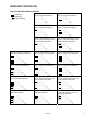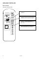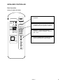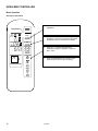
1
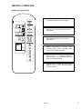
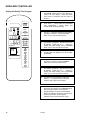
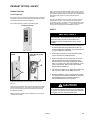
8-507.3
5H101551A Rev. C
July, 2009
INSTALLATION AND SERVICE MANUAL
Infra-Red Remote Controller for
Ceiling Cassettes with Microprocessor Controls
3087217
The ETL Listed Mark indicates that your product has been
tested by Intertek, found in compliance with accepted
national standards, and meets the minimal requirements
required for sale or distribution. To your distributors,
retailers, and customers, the ETL Mark is assurance that the
product is compliant with safety standards, having been
tested and certified by a third-party organization.
INSPECTION on ARRIVAL:
1.
2.
IMPORTANT
The use of this manual is specifically intended for a
qualified installation and service agency. A qualified
installation and service agency must perform all
installation and service of these appliances.
3.
Inspect unit upon arrival. In case of damage, report
immediately to transportation company and your local
sales representative.
Check rating plate on unit to verify that the power
supply meets available electric power at the point of
installation.
Inspect unit received for conformance with description
of product ordered (including specifications where
applicable).
This manual is the property of the owner.
Please be sure to leave it with the owner when you leave the job.
SPECIAL PRECAUTIONS / TABLE OF CONTENTS
SPECIAL PRECAUTIONS
TABLE OF CONTENTS
THE INSTALLATION AND MAINTENANCE INSTRUCTIONS IN
THIS MANUAL MUST BE FOLLOWED TO PROVIDE SAFE,
EFFICIENT, AND TROUBLE-FREE OPERATION. IN ADDITION,
PARTICULAR CARE MUST BE EXERCISED REGARDING THE
SPECIAL PRECAUTIONS LISTED BELOW. FAILURE TO
PROPERLY ADDRESS THESE CRITICAL AREAS COULD
RESULT IN PROPERY DAMAGE OR LOSS, PERSONAL INJURY,
OR DEATH. THESE INSTRUCTIONS ARE SUBJECT TO ANY
MORE RESTRICTIVE LOCAL OR NATIONAL CODES.
HAZARD INTENSITY LEVELS
1. DANGER: Indicates an imminently hazardous situation
which, if not avoided, WILL result in death or serious
injury.
2. WARNING: Indicates a potentially hazardous situation
which, if not avoided, COULD result in death or serious
injury.
3. CAUTION: Indicates a potentially hazardous situation
which, if not avoided, MAY result in minor or moderate
injury.
4. IMPORTANT: Indicates a situation which, if not
avoided, MAY result in a potential safety concern.
WARNING
Inspection on Arrival…………………….....………….
Special Precautions………………..………………….
Hazard Intensity Levels……………………………….
SI (Metric) Conversion Factors……………..………..
Introduction…………………………………..…………
Model Number Description………………….………..
General Description…………………………………...
PCB Control Board……………………………..……..
Infra-Red Controller
Transmitter……..……………………………….
Receiver / Self Diagnostics……………………
Receiver Indication Reference Guide………..
Basic Operation: Settings for COOL ONLY….
Basic Operation: Settings for HEAT ONLY….
Basic Operation: Settings for AUTO Mode….
Setting the Current Time……………………….
Setting the Weekly Time Program…………….
Method of Operation
Setting Jumper Links……………………………
Software Control………………………………..
Main Control Functions………………………..
Alarms……………………………………………
Network Option – Microprocessor Control…………
Pendant Option……………………………………….
Safety…………………………………………………..
Warranty………………………………………………..
1. Disconnect power supply before making wiring
connections to prevent electrical shock and equipment
damage.
2. All appliances must be wired strictly in accordance
with wiring diagram furnished with the appliance. Any
wiring different from the wiring diagram could result in
a hazard to persons and property.
3. Any original factory wiring that needs replacement
must be replaced with wiring material having a
temperature rating of at least 105ºC.
4. Ensure that the supply voltage to the appliance, as
indicated on the serial plate, is not 5% greater than the
rated voltage.
CAUTION
This product must be installed in strict compliance with the
enclosed installation instructions and any applicable local,
state, and national codes including, but not limited to,
building, electrical, and mechanical codes.
2
8-507.3
1
2
2
3
3
3
3
4
5
6
7
8
9
10
11
12
13
13
13
14
14
15
15
16
SI CONVERSION FACTORS / GENERAL DESCRIPTION
SI (Metric) CONVERSION FACTORS
To
Convert
“W.C.
Psig
ºF
Inches
Feet
CFM
Multiply
By
0.24
6.893
(ºF-32)
x0.555
25.4
0.305
0.028
GENERAL DESCRIPTION
To
Obtain
kPa
kPa
ºC
To
Convert
CFH
BTU/ft²
pound
Multiply
By
1.699
0.0374
0.453
To
Obtain
m³/min
mJ/m³
Kg
Controller - Before using the Infra-Red (IR) Transmitters, please
read this handbook fully and ensure the batteries (supplied loose)
are fitted into the IR transmitter or Pendant.
Mm
Meters
m³/min
BTU/hr
Gallons
Psig
0.000293
3.785
27.7
kW/hr
Liters
“W.C.
A microprocessor mounted in a metal enclosure is used to control
the entire unit operating functions with adjustments and settings
being made from a hand-held IR transmitter or Pendant.
INTRODUCTION
The Ceiling Cassette units effectively make each area served an
independent controlled temperature zone. Through thermostatic
control of operations, conditions can be varied to suit diverse
requirements or activities. Optional fresh air intakes are available to
provide for ventilation and recirculation of room air.
Ceiling Cassettes are available in a choice of three models – DX
cooling and heat pumps in five model sizes and chilled water
cooling in six model sizes – to properly match units to job
requirements. Optional heating can be provided by factory installed
electric heat or hot water modules, depending on model. This
versatility eliminates compromising architecture or design. Important
cost savings are often realized during building modernizations, as
existing piping and/or wiring can frequently be reused.
Design techniques are incorporated in every Ceiling Cassette to
reduce noise levels to an absolute minimum. These techniques
include low blower speeds, rigid panel and cabinet construction,
and sound-absorbent cabinet insulation.
The controls comprise of the following basic components:
PCB Control Board
Infra-Red Transmitter or Pendant
Infra-Red Receiver (mounted on the fascia)
Microprocessor Control Board - The PCB control board
relays control the operation of the indoor fan motor, outdoor fan
motor, compressor and electric heater (if fitted), to maintain room
conditions at a user defined set point. Temperature settings, fan
speeds and other control functions can be changed by the IR
transmitter or Pendant. The controller PCB provides the following
input/output facilities:
Inputs (3)
T1 Return Air Temperature Sensor
50K @ 77°F NTC.
T3 Indoor Coil Temperature Sensor
50K @ 77°F NTC.
T2 Defrost Signal (Switched 24VAC signal from Condensing Unit)
Outputs
Indoor Fan Motor
For individual comfort, Ceiling Cassettes are available with electromechanical or micro-processor based controls. The microprocessor controller includes an infrared transmitter which enables
room conditions to be maintained at a user defined set point.
Ceiling Cassettes are also available with Carel microprocessor
controls and network cards to allow units to be connected to a
Building Management System.
MODEL IDENTIFICATION
CEILING CASSETTE UNITS
CSD or SSD
CSH or SSH
CCW or SCW
Base Model:
Ceiling Cassette Unit – DX Cooling
Ceiling Cassette Unit – Heat Pump
Ceiling Cassette Unit – Chilled Water
8 to 42
Model Size:
Nominal Cooling in BTU/Hr (See Performance
Data for Details)
2/ or _ (blank)
Cabinet Size:
2/ = Small Body (2 X 2 Series)
_ = Medium Body (3 X 3 Series) or
Large Body (3 X 4 Series)
EM, MC or CA
Control Type:
EM = Electro-Mechanical Control
MC = Microprocessor Controlled – Remote
Control, Infrared or Pendant
CA = Carel Controller
Example:
CSD ( or SSD) 18MC =
Ceiling Cassette Unit, DX Cooling, 18,000
Nominal BTU/Hr, Microprocessor Controlled
Compressor
The controller will switch a combination of
3, 10A 230 VAC (3 Speed Settings)
resistive rated relays to deliver the
selected indoor fan speed.
A 30A 230 VAC resistive rated relay is
used to switch the compressor by a
contactor in the outdoor unit enabling
cooling or heat pump operation.
Reversing Valve (RV)
A 10A 230 VAC resistive rated relay is
used to switch the reversing valve in a
heat pump unit.
Condensate Pump
Activated when unit is in cooling mode
(Cassette units only).
Vane Motor
A 10A 230VAC resistive rated relay
switches the vane motor on when Air
Sweep is selected (Med. & Large Cassette
Units only).
Electric Heat
A 30A 230VAC resistive rated relay
switches the electric heater on when
required.
External Connections
Power Input
Network Connection
Nominal 230 Volt AC 60Hz
Twisted pair shielded cable
Microprocessor PCB Battery
The microprocessor PCB is fitted with a battery back up
system that maintains the CPU memory and time clock
settings during brief power outages. The battery is small,
round and silver in appearance, similar to a wrist watch
battery. When the unit is shipped, the battery is packed in a
plastic bag and is placed inside the small rectangular box
containing the infra-red transmitter. The battery should be
installed into the PCB’s battery holder (see page 4 for
location details) approximately 5 minutes before mains
power is initially applied to the unit.
8-507.3
3
4
SW
F1
8-507.3
Condensate
Pump
W
FH
230VAC
Terminal
L2
0
Vane Motor
Output
HEAT
IN
HEAT
OUT
COMP
IN
COMP
OUT
L1
10A Fuse
FL
Indoor Fan
3 Speeds
FM
Reversing
Valve In
HP
Transformer
Reversing
Valve Out
HP
JMP3
Pendant
Connector
JMP2
(See page 2 for battery
installation instructions)
Jumper Links
JMP1
Battery
– – S S1 RC
230VAC
Heater
Supply
L2
Heat
Output
Compressor
In
Compressor
Out
230VAC
Terminal
T3 = Indoor Coil
T2 = Defrost Input
T1 = Room Sensor
Sensor
IR Receiver
Connector
Network Terminals
For Master/Slave
MICROPROCESSOR CONTROL BOARD
PCB Control Board
T1 T1 T2 T2 T3 T3
CPU
INFRA-RED CONTROLLER
Transmitter
When using the IR transmitter, always point the transmitter head directly at the receiver. At the time of
transmission the
symbol will display and an audible alarm will be heard if the signal has been
received.
When the batteries are first installed, the transmitter or Pendant will have a default setpoint of 64ºF, low
fan speed will be selected and the system will be set to cool only mode.
ON/SEND:
Pressing this button will switch
the unit on and transmit the
system settings.
TRANSMIT INDICATOR:
This symbol will flash when the
system settings are transmitted.
ON/SEND
MODE INDICATOR:
Highlighted symbol indicates
current mode of operation.
MODE
A
FAN MODE INDICATOR:
Highlighted symbol indicates
current fan operating mode.
FAN
A
_
CLOCK/TIMER DISPLAY:
Shows current day, time and
stop/start times.
SETPOINT DISPLAY:
Indicates current room
temperature setpoint.
SWING INDICATOR:
Indicates operation of the air
vanes (Med Large cassettes only)
SLEEP INDICATOR:
Indicates when sleep mode is
selected.
FAN:
Pressing this button will cycle through
the fan speed options, LOW, MED,
HIGH & AUTO.
CLK/TIMER:
Pressing these buttons will select and
adjust the clock and stop/start times.
CLK/TIMER
WE
72
+
MODE:
Pressing this button will cycle through
the mode options, COOL, AUTO,
DRY, FAN & HEAT.
+
ºF
TEMP
_
SLEEP
SWING
OFF
TEMP:
Pressing these buttons will adjust the
room temperature setpoint.
SLEEP:
Pressing this button will cause the
room temperature setpoint to be
setback 2°F after first hour, 4°F after
second hour.
SWING:
Pressing this button will operate the air
vanes (Med Large cassettes only).
OFF:
Pressing this button will switch the
unit off.
8-507.3
5
INFRA-RED CONTROLLER
Receiver
The IR receiver is an extension of the control board and is located on the fascia of the unit,
connected by means of a 7 pin plug and socket.
The green On/Off indicator will be either permanently illuminated when the unit is running or
flashes if heating or cooling is called for but the compressor anti-cycle timer is delaying compressor
operation.
Yellow indicators show the present unit status ‘cool’ or ‘heat’.
When both yellows flash, the PCB control board battery needs changing (see page 3).
Note: Take care when changing the battery as the holder can be damaged.
Self Diagnostics
The microprocessor controller has a built-in diagnostics feature so that in the event of an alarm, the
nature of the fault can be determined. The red timer/alarm LED flashes on the fascia in a predetermined frequency depending on the fault.
These are identified below:
1
2
Alarm LED flashes once every second - indoor coil sensor failure, low coil
temperature, condensate high level trip or remote shutdown activated.
Alarm LED flashes once every 5 seconds - return air sensor failure.
Note: When the microprocessor is used in a master / slave network AND is configured for slave
operation, both the cool and heat indicators will be permanently lit, even during periods when the
unit is switched off.
6
8-507.3
INFRA-RED CONTROLLER
Receiver Indication Reference Guide
Unit Off, timer operation off, indoor
fan off, cooling and heating off.
Unit Off, timer operation on, indoor
fan off, cooling and heating off.
Unit On, timer operation off, indoor
fan on, cooling and heating off.
Unit On, timer operation on, indoor
fan on, cooling and heating off.
Unit On, timer operation off, indoor
fan on, cooling and heating off, anticycle protection delay active.
Unit On, timer operation on, indoor
fan on, cooling and heating off, anticycle protection delay active.
Unit On, indoor fan on, Timer off
slave unit controlled by master unit.
Unit On, timer operation off, indoor
fan on, cooling on, and heating off.
Unit On, timer operation on, indoor
fan on, cooling on, and heating off.
Unit On, timer operation off, indoor
fan on, check main PCB battery.
Unit On, timer operation off, indoor
fan on, cooling off, and heating on.
Unit On, timer operation on, indoor
fan on, cooling off, and heating on.
Unit On, timer operation on, indoor
fan on, check battery backup.
Unit On, timer operation off, indoor
fan on, cooling off, heating on, anticycle protection delay active.
Unit On, timer operation on, indoor
fan on, cooling off, heating on, anticycle protection delay active.
Unit On, alarm present, indoor fan on,
check battery backup.
Unit On, alarm present, indoor fan on,
cooling off, heating off.
Unit On, alarm present, indoor fan on,
cooling off, heating off, anti-cycle
protection delay active.
Indicator Off
Indicator On
Indicator Flashing
8-507.3
7
INFRA-RED CONTROLLER
Basic Operation
Settings for COOL ONLY Mode
1
Press MODE Button until the Cool symbol is
highlighted.
2
Press FAN Button until the desired fan speed is
highlighted. Note that in Auto the fan speed will
be determined by the temperature conditions.
3
Press the + / - buttons until the desired
temperature set point is displayed. Limits are
58°F – 90°F.
4
Press the ON/SEND button to switch the unit
ON and transmit the new system settings.
ON/SEND
MODE
A
FAN
A
_
CLK/TIMER
WE
72
+
+
ºF
TEMP
_
SLEEP
SWING
OFF
8
8-507.3
INFRA-RED CONTROLLER
Basic Operation
Settings for HEAT ONLY Mode
1
Press MODE Button until the Heat symbol is
highlighted.
2
Press FAN Button until the desired fan speed is
highlighted. Note that in Auto the fan speed will
be determined by the temperature conditions.
3
Press the + / - buttons until the desired
temperature setpoint is displayed. Limits are
58°F – 90°F.
4
Press the ON/SEND button to switch the unit
ON and transmit the new system settings.
ON/SEND
MODE
A
FAN
A
_
CLK/TIMER
WE
77
+
+
ºF
TEMP
_
SLEEP
SWING
OFF
8-507.3
9
INFRA-RED CONTROLLER
Basic Operation
Settings for AUTO Mode
1
Press MODE Button until the Auto symbol is
highlighted.
2
Press FAN Button until the desired fan speed is
highlighted. Note that in Auto the fan speed will
be determined by the temperature conditions.
3
Press the + / - buttons until the desired
temperature setpoint is displayed. Limits are
58°F – 90°F.
4
Press the ON/SEND button to switch the unit
ON and transmit the new system settings.
ON/SEND
MODE
A
FAN
A
_
CLK/TIMER
WE
77
+
+
ºF
TEMP
_
SLEEP
SWING
OFF
10
8-507.3
METHOD of OPERATION
Setting the Current Time
1
Press CLK/TIMER button once, you should see
“CLOCK SET” flashing in the time display.
2
Press either + / - buttons within the CLK/TIMER
area, the hours of the current time should now
start to flash.
3
Use the + / - buttons to change the hour setting.
Press CLK/TIMER button once to enter the
selected hour.
4
The minutes of the current time should now be
flashing. Again use the + / - buttons to change
the minute setting. Press CLK/TIMER button
once to enter the selected minutes.
5
The current weekday should now be flashing.
Again use the + / - buttons to change the
weekday setting. Press CLK/TIMER button once
to enter the selected weekday.
6
“CLOCK SET” in the time display should now
disappear and the current time and weekday
have now been set.
ON/SEND
MODE
A
FAN
A
_
+
CLK/TIMER
WE
CLOCK
SET
77
+
ºF
TEMP
_
SLEEP
SWING
OFF
8-507.3
11
INFRA-RED CONTROLLER
Setting the Weekly Time Program
1
Press CLK/TIMER button twice, you should see
“PROGRAM” flashing and the days Monday to
Friday in the time display. (Press the button
three times for Saturday and four times for
Sunday.)
2
Press either + / - buttons within the CLK/TIMER
area, “PROGRAM 1” should appear and
“START TIME” should be flashing.
3
Use the + / - buttons to change the hour setting
of program 1 start time. Press CLK/TIMER
button once to enter the selected hour.
4
The minutes of program 1 start time should now
be flashing. Again use the + / - buttons to
change the minute setting. Press CLK/TIMER
button once to enter the selected minutes.
5
“START TIME” will disappear and “STOP TIME”
should flash.
6
Use the + / - buttons to change the hour setting
of program 1 stop time. Press CLK/TIMER
button once to enter the selected hour.
7
The minutes of program 1 stop time should now
be flashing. Again use the + / - buttons to
change the minute setting. Press CLK/TIMER
button once to enter the selected minutes.
8
If program 2 is to be used then repeat from
steps 3 – 7. If program 2 is not to be used,
leave the start \ stops set to 12:00am.
9
When the programming is complete “SEND” will
flash in the time display, press ON/SEND button
while pointing at receiver, to transmit the
program settings. The main unit should beep
and the red indicator should be lit. A small clock
should be seen within the time display,
indicating a time program has been set-up.
ON/SEND
MODE
A
FAN
A
_
MO TU WE TH FR
PROGRAM 1
72
+
CLK/TIMER
+
ºF
TEMP
_
SLEEP
SWING
OFF
12
8-507.3
METHOD OF OPERATION
METHOD OF OPERATION
Heat Pump Units
SETTING JUMPER LINKS
The control system allows the selection of heat pump or non heat
pump modes via jumper 2. Non heat pump units can have only
one stage of heating, (optional), which is enabled by the electric
heater relay. Heat pump units can have up to two stages of
heating, the first stage being heat pump and the optional second
stage is electric heating (boost heat).
Jumper links are located on the Microprocessor Controller PCB
to offer different control features and their functionality is listed
below:
Jumper Links
JMP1
JMP2
JMP3
ON
Reversing Valve (RV)
On in Cooling (factory)
Heat Pump Mode (See
Wiring Diagram)
Unit is Stand Alone /
Master (Factory)
OFF
RV On in Heating
Defrost
Non Heat Pump
Mode / CW
Unit is Slave
Is initiated by the outdoor unit, a 24vac signal is sent to T2
terminals on the cassette micro. This then turns on the electric
heat if available, to act as re-heat.
Boost Heat
Jumper link settings must be made with the power turned off and
PCB battery removed. Jumper link 1 will be factory set to ON,
jumper link 2 will be factory set to suit the type of unit. Jumper
link 3 will be factory set to ON, should a Master/Slave system be
required jumper link 3 will require setting during the startup of the
units.
The electric heat relay can be used to initiate either low watts
density electric heating or low pressure hot water heating, neither
of which is fitted as standard, but are available as options. The
boost heat will be activated when the room temperature falls to
more than 8ºF below setpoint. Hysteresis of 2ºF will be applied
to prevent “hunting”. The boost heat facility is automatically
enabled/disabled by selecting non heat pump (Jumper 2. open).
WARNING
Temperature Control
1. Disconnect power supply before making wiring connections
to prevent electrical shock and equipment damage.
2. All appliances must be wired strictly in accordance with
wiring diagram furnished with the appliance. Any wiring
different from the wiring diagram could result in a hazard to
persons and property.
3. Any original factory wiring that needs replacement must be
replaced with wiring material having a temperature rating of
at least 105ºC.
4. Ensure that the supply voltage to the appliance, as
indicated on the serial plate, is not 5% greater than the
rated voltage.
The controller will switch heating or cooling loads in order to
maintain the temperature setpoint. The dead band is
programmed to 4ºF. Under normal operation, cooling or heating
will be activated at the limits of the dead band and will continue to
operate until setpoint is achieved.
The temperature setpoint can be adjusted between 58 and 90ºF
in 2ºF increments.
Compressor Protection
The compressor is protected by a ten minute consecutive start
delay and a four minute stop to start delay, e.g. if the compressor
has run for over ten minutes, stops and is then required to restart
immediately, there will be a four minute time delay before the
compressor runs. If the compressor has run for only four
minutes, stops and is then required to restart immediately, there
will be a six-minute time delay before the compressor runs.
These delays are to prevent unnecessary wear and potential
damage to the compressor motor. While the unit is switched on
and either of the compressor’s start delays are active the Green
On/Off LED on the IR receiver will flash at one second intervals.
As a further protection, compressor operation will be inhibited if
the indoor coil temperature falls below 28ºF.
SOFTWARE CONTROL
The control system software performs the following primary
functions:
• Control of the indoor fan, compressor, heat pump and electric
heater to achieve and maintain the temperature setpoint.
• Monitor status and temperature inputs for error conditions
and shutdown the relevant outputs in the event of a fault
occurring.
• Communicate with other controllers when operating in a
Master/Slave set-up.
• Receive coded IR data from the hand held IR transmitter or
Pendant and adjust control parameters as instructed.
• Operate to time functions if they are required.
Power Failure
The controller will auto restart in its previous mode of operation
after a power failure. When power is restored the controller will
revert to its last operating mode, e.g. if the controller was turned
on before power fail, after power is restored the controller will
automatically turn on. Alternatively if the controller was turned off
before power fail after power is restored the controller will remain
off.
MAIN CONTROL FUNCTIONS
Indoor Fan Operation
Battery Backup
The indoor fan will run continuously at the most recently set
speed or will alter the speed according to the room temperature
conditions when set to Auto. The indoor fan will continue to run
until the unit is turned off by the user or via a pre-set time setting.
When the unit is turned off during heating, the indoor fan will
continue to run for approximately two minutes, this helps to
dissipate residual heat from the electric heaters. In SLEEP mode
the fan will cycle with a call for heating or cooling.
To maintain all the user and time clock settings during a power
off situation, a 10 year battery backup has been provided. When
the battery requires replacing the Cool and Heat status LED’s on
the IR receiver will flash at 1 second intervals. This assumes
normal power outages. With no power the battery will last up to
three months.
8-507.3
13
METHOD OF OPERATION / NETWORK OPTION
Master/Slave Operation
ALARMS
The network option allows for 1 “master” unit and up to 19 “slave”
units to be interconnected using a twin twisted pair screened
cable to create a network.
The controller monitors the following alarm conditions:
• Return Air Sensor Failure
• Indoor Coil Sensor Failure
• Condensate High Level
• High Pressure Switch Trip (Heat pump units only)
• Indoor Coil Over Temperature (Heat pump units only)
• Indoor Coil Under Temperature
• Battery Backup Low Voltage
The master/slave operation has been programmed to operate the
units in the following manner:
When the master unit receives a transmission from the
transmitter, the transmitter settings are provided to all units on
the network.
Indoor Coil Under-Temperature
Slave units do NOT monitor the return air temperature but rely
instead on the master unit to monitor return air temperature and
make all control decisions. Slave units will mimic the operation of
the master unit and will cool, heat, switch on, switch off etc, with
the Master. When the units are configured as heat pumps the
defrost program is operated independently, to avoid unnecessary
defrosting and loss of heating performance.
In cooling mode, if the indoor coil sensor realizes a temperature
of 28ºF or less for a period exceeding two and a half minutes, the
controller will switch off the compressor and outdoor fan until the
coil temperature has remained above 40ºF for a period
exceeding six minutes. When the compressor and outdoor fan
are disabled in this manner the indoor fan will operate at high
speed and the Timer LED on the IR receiver will flash at one
second intervals.
At all times the slave units will follow the usual method of
operation regarding alarms and will act accordingly. When a
master unit experiences an alarm it will act in the usual manner
while maintaining instruction to slave units to operate normally.
The exception to this is when the Master unit experiences a
return air sensor failure. Due to the fact that it cannot control
correctly, the Master unit will instruct the slave units to revert to
stand alone operation.
Indoor Coil Over-Temperature
During heat pump mode, the electric heaters will be switched
off if the indoor coil sensor realizes a temperature greater
than 140ºF for a period exceeding one minute. The electric
heater will remain switched off and the indoor fan will operate
at high speed until the coil temperature has remained below
130ºF for a period exceeding 8 minutes.
In the event of the network cable being severed or
communications between Master and Slaves being lost for any
reason, the slave units will revert to stand alone control after six
minutes without instruction from the Master. During this time the
slaves will monitor the return air temperature themselves and will
make their own control decisions based upon the last set of
transmitter settings received from the Master.
Electric Heater Overheat Protection
In the event of an auto reset overheat cut-out, the electric heater will
be switched off until the temperature drops sufficiently for the auto
cut-out to reset itself. Should the manual reset overheat cut-out
operate, the electric heater will be switched off and remain off until
the reset button on the manual overheat cut-out is pressed.
(SWITCH OFF POWER TO UNIT BEFORE RESETTING).
Network Connection
The network cable is routed between controllers and terminated
at each unit in the manner shown below:
Note: The cable screen is provided to prevent signals being
imposed on and corrupting the data carried by the 2 cable cores.
The screen must be grounded at only one end for each unit on
the network.
High Condensate Level Alarm
On occurrence of a high condensate level condition, the compressor
will stop. When the high condensate alarm level condition clears the
compressor will automatically switch back on, providing the
compressor protection delays are not active.
A remote shutdown is possible by installing a dry contact
between the indoor coil sensor and terminal T3. When the
contact is closed the unit operation is normal. When the contact
is open the unit will be shutdown and the alarm light will flash
once per second.
NETWORK OPTION – MICROPROCESSOR
CONTROLLER
M aster U nit
RC S1
S
_
Slave Unit 2
S lave U nit 1
_
RC S 1
S
_
_
RC S1
S
_
_
To next unit –
To next unit S1
To O ther U nits
14
8-507.3
PENDANT OPTION / SAFETY
Note: The Pendant controller transmits a signal to the unit via an
optical lens on the back of the controller to the mounting bracket.
The Pendant controller MUST be mounted in the wall bracket and
operated from this position to communicate with the unit
controller.
PENDANT OPTION
Pendant (Optional)
The pendant option is a hard-wired replacement for the hand held
transmitter, it has all the functionality of the transmitter but is field
mounted and therefore cannot be misplaced.
Plug the 2 way female connector on other end of the cable into
the “pendant connector” on the cassette unit microprocessor
circuit board. Finally, connect the screen wire to the either one of
the two network terminals marked “– “. (The pendant connector
and network terminal positions are illustrated on page 4).
The Pendant assembly consists of the following parts:
Pendant Controller
SAFETY
IMPORTANT
The information contained in this manual is critical to the
correct operation and maintenance of the unit and
should be read by all persons responsible for the
installation, start up and maintenance of the Ceiling
Cassette.
1. The equipment has been designed and manufactured
to meet international safety standards but, like any
mechanical/electrical equipment, care must be taken if
you are to obtain the best results.
Pendant Wall Mounting
Bracket
Reverse of Wall Mounting
Bracket, Showing cable
connection
2. Service and maintenance of this equipment should
only be carried out by skilled personnel.
3. When working with any air conditioning unit, ensure
that the electrical disconnect supplying the unit is
switched off prior to servicing or repair work and that
there is no power to any part of the equipment. In the
case of a DX system, both the indoor and outdoor
units should be switched off.
C
B
4. Also ensure that there are no other power feeds to the
unit such as fire alarm circuits, BMS circuits, etc.
A
5. Electrical installation, start up and maintenance work
on this equipment should be undertaken by competent
and trained personnel in accordance with local
relevant standards and codes of practice.
Position the wall bracket and mark through the 2 fixing holes
(Item A).
CAUTION
Connect the 3 way female cable connector (Item B) with the male
bracket connector (Item C). The cable can be routed from either
the top or the left hand side of the wall bracket and the bracket
then affixed to the wall.
This product must be installed in strict compliance with
the enclosed installation instructions and any applicable
local, state, and national codes including, but not limited
to, building, electrical, and mechanical codes.
Slide the Pendant controller into the wall bracket, from the top, to
complete the assembly.
8-507.3
15
COMMERCIAL WARRANTY
Seller warrants its products to be free from defects in material and
workmanship, EXCLUSIVE, HOWEVER, of failures attributable to the use of
materials substituted under emergency conditions for materials normally
employed. This warranty covers replacement of any parts furnished from
the factory of Seller, but does not cover labor of any kind and materials not
furnished by Seller, or any charges for any such labor or materials, whether
such labor, materials or charges thereon are due to replacement of parts,
adjustments, repairs, or any other work done. This warranty does not apply
to any equipment which shall have been repaired or altered outside the
factory of Seller in any way so as, in the judgment of Seller, to affect its
stability, nor which has been subjected to misuse, negligence, or operating
conditions in excess of those for which such equipment was designed. This
warranty does not cover the effects of physical or chemical properties of
water or steam or other liquids or gases used in the equipment.
BUYER AGREES THAT SELLER’S WARRANTY OF ITS PRODUCTS TO
BE FREE FROM DEFECT IN MATERIAL AND WORKMANSHIP, AS
LIMITED HEREIN, SHALL BE IN LIEU OF AND EXCLUSIVE OF ALL
OTHER WARRANTIES, EITHER EXPRESS OR IMPLIED, WHETHER
ARISING FROM LAW, COURSE OF DEALING, USAGE OF TRADE, OR
OTHERWISE, THERE ARE NO OTHER WARRANTIES, INCLUDING
WARRANTY OF MERCHANTABILITY OR FITNESS FOR PURPOSE,
WHICH EXTEND BEYOND THE PRODUCT DESCRIPTION CONFIRMED
BY BUYER AND SELLER AS OF THE DATE OF FINAL AGREEMENT.
This warranty is void if the input to the product exceeds the rated input as
indicated on the product serial plate by more than 5% on gas-fired and oilfired units, or if the product in the judgment of SELLER has been installed in
a corrosive atmosphere, or subjected to corrosive fluids or gases, been
subjected to misuse, negligence, accident, excessive thermal shock,
excessive humidity, physical damage, impact, abrasion, unauthorized
alterations, or operation contrary to SELLER’S printed instructions, or if the
serial number has been altered, defaced or removed.
DEFINED HEREIN AND UPON PRIOR WRITTEN APPROVAL, BE
RETURNED TO SELLER WITH TRANSPORTATION CHARGES PREPAID
AND WHICH THE EXAMINATION OF SELLER SHALL DISCLOSE TO
HAVE BEEN DEFECTIVE; EXCEPT THAT WHEN THE PRODUCT IS TO
BE USED BY BUYER AS A COMPONENT PART OF EQUIPMENT
MANUFACTURED BY BUYER, BUYER’S REMEDY FOR BREACH, AS
LIMITED HEREIN, SHALL BE LIMITED TO ONE YEAR FROM DATE OF
SHIPMENT FROM SELLER. FOR GAS-FIRED PRODUCTS INSTALLED IN
HIGH HUMIDITY APPLICATIONS AND UTILIZING STAINLESS STEEL
HEAT EXCHANGERS, BUYER’S REMEDY FOR BREACH, AS LIMITED
HEREIN, SHALL BE LIMITED TO TEN YEARS FROM DATE OF
SHIPMENT FROM SELLER.
These warranties are issued only to the original owner-user and cannot be
transferred or assigned. No provision is made in these warranties for any
labor allowance or field labor participation. Seller will not honor any
expenses incurred in its behalf with regard to repairs to any of Seller’s
products. No credit shall be issued for any defective part returned without
proper written authorization (including, but not limited to, model number,
serial number, date of failure, etc.) and freight prepaid.
OPTIONAL SUPPLEMENTAL WARRANTY
Provided a supplemental warranty has been purchased, Seller extends the
warranty herein for an additional four (4) years on certain compressors.
Provided a supplemental warranty has been purchased, Seller extends the
warranty herein for an additional four (4) years or nine (9) years on certain
heat exchangers.
EXCLUSION OF CONSUMABLES & CONDITIONS BEYOND SELLER’S
CONTROL
The above referenced warranty shall not be applicable to any of the
following items: refrigerant gas, belts, filters, fuses and other items
consumed or worn out by normal wear and tear or conditions beyond
Seller’s control, including (without limitation as to generality) polluted or
contaminated or foreign matter contained in the air or water utilized for heat
exchanger (condenser) cooling or if the failure of the part is caused by
improper air or water supply, or improper or incorrect sizing of power supply.
BUYER’S REMEDY FOR BREACH OF WARRANTY, EXCLUSIVE OF ALL
OTHER REMEDIES PROVIDED BY LAW, IS LIMITED TO REPAIR OR
REPLACEMENT AT THE FACTORY OF SELLER, ANY COMPONENT
WHICH SHALL, WITHIN THE APPLICABLE WARRANTY PERIOD
Component
“APPLICABLE WARRANTY PERIOD”
Applicable Models
Heat Exchangers
TEN YEARS FROM DATE OF FIRST BENEFICIAL USE BY BUYER OR ANY OTHER USER, WITHIN
Gas-Fired Units except PSH/BSH
TEN YEARS FROM DATE OF RESALE BY BUYER OR ANY OTHER USER, WITHIN TEN YEARS FROM
DATE OF RESALE BY BUYER IN ANY UNCHANGED CONDITION, OR WITHIN ONE HUNDRED
TWENTY-SIX MONTHS FROM DATE OF SHIPMENT FROM SELLER, WHICHEVER OCCURS FIRST
Heat Exchangers
FIVE YEARS FROM DATE OF FIRST BENEFICIAL USE BY BUYER OR ANY OTHER USER, WITHIN
Low Intensity Infrared Units
FIVE YEARS FROM DATE OF RESALE BY BUYER OR ANY OTHER USER, WITHIN FIVE YEARS
FROM DATE OF RESALE BY BUYER IN ANY UNCHANGED CONDITION, OR WITHIN SIXTY-SIX
Compressors
MONTHS FROM DATE OF SHIPMENT FROM SELLER, WHICHEVER OCCURS FIRST
Condensing Units for Cassettes
Burners
Low Intensity Infrared Units
TWO YEARS FROM DATE OF FIRST BENEFICIAL USE BY BUYER OR ANY OTHER USER, WITHIN
TWO YEARS FROM DATE OF RESALE BY BUYER IN ANY UNCHANGED CONDITION, OR WITHIN
Other
THIRTY MONTHS FROM DATE OF SHIPMENT FROM SELLER, WHICHEVER OCCURS FIRST
Components excluding Heat Exchangers,
Coils, Condensers, Burners, Sheet Metal
Heat Exchangers/Coils
Indoor and Outdoor Duct Furnaces and
System Units, PSH/BSH, Steam/Hot Water
Units, Oil-Fired Units, Electric Units,
Cassettes, Vertical Unit Ventilators
Compressors
Vertical Unit Ventilators
ONE YEAR FROM DATE OF FIRST BENEFICIAL USE BY BUYER OR ANY OTHER USER, WITHIN
ONE YEAR FROM DATE OF RESALE BY BUYER IN ANY UNCHANGED CONDITION, OR WITHIN
EIGHTEEN MONTHS FROM DATE OF SHIPMENT FROM SELLER, WHICHEVER OCCURS FIRST
Burners
High Intensity Infrared Units
Sheet Metal Parts
All Products
Modine Manufacturing Company has a continuous product improvement program, and therefore reserves the right to change design and specifications without notice.
CSD, CSH and CCW Model Series
Phone: 1.866.823.1631 (Toll Free)
www.airedaleusa.com
SSD, SSH and SCW Model Series
Phone: 1.800.828.4328 (HEAT)
www.modine.com
© Modine Manufacturing Company 2009
Commercial Products Group
Modine Manufacturing Company
1500 DeKoven Avenue
Racine, WI 53403
07/09 Litho in USA