1
D096
SERVICE MANUAL
005627MIU
D096
SERVICE MANUAL
D096
SERVICE MANUAL
005627MIU
It is the reader's responsibility when discussing the information contained
within this document to maintain a level of confidentiality that is in the best
interest of Ricoh Americas Corporation and its member companies.
NO PART OF THIS DOCUMENT MAY BE REPRODUCED IN ANY
FASHION AND DISTRIBUTED WITHOUT THE PRIOR
PERMISSION OF RICOH AMERICAS CORPORATION.
All product names, domain names or product illustrations, including
desktop images, used in this document are trademarks, registered
trademarks or the property of their respective companies.
They are used throughout this book in an informational or editorial fashion
only and for the benefit of such companies. No such use, or the use of
any trade name, or web site is intended to convey endorsement or other
affiliation with Ricoh products.
© 2010 RICOH Americas Corporation. All rights reserved.
WARNING
The Service Manual contains information
regarding service techniques, procedures,
processes and spare parts of office equipment
distributed by Ricoh Americas Corporation.
Users of this manual should be either service
trained or certified by successfully completing a
Ricoh Technical Training Program.
Untrained and uncertified users utilizing
information contained in this service manual to
repair or modify Ricoh equipment risk personal
injury, damage to property or loss of warranty
protection.
Ricoh Americas Corporation
LEGEND
PRODUCT
CODE
D096
GESTETNER
MP 1900
COMPANY
LANIER
RICOH
LD319
MP 1900
SAVIN
N/A
DOCUMENTATION HISTORY
REV. NO.
*
DATE
04/2010
COMMENTS
Original Printing
D096
TABLE OF CONTENTS
PRODUCT INFORMATION
1. PRODUCT INFORMATION...........................................................1-1 1.1 SPECIFICATIONS ..................................................................................... 1-1 1.2 MACHINE CONFIGURATION ................................................................... 1-2 1.3 GUIDANCE FOR THOSE WHO ARE FAMILIAR WITH PREDECESSOR
PRODUCTS ..................................................................................................... 1-3 1.4 OVERVIEW ................................................................................................ 1-4 1.4.1 COMPONENT LAYOUT ................................................................... 1-4 1.4.2 PAPER PATH ................................................................................... 1-6 1.4.3 DRIVE LAYOUT ................................................................................ 1-7
INSTALLATION
2. INSTALLATION ............................................................................2-1 2.1 INSTALLATION REQUIREMENTS ............................................................ 2-1 2.1.1 ENVIRONMENT ............................................................................... 2-1 2.1.2 MACHINE LEVEL ............................................................................. 2-2 2.1.3 MINIMUM SPACE REQUIREMENTS ............................................... 2-3 2.1.4 POWER REQUIREMENTS............................................................... 2-3 2.2 COPIER INSTALLATION ........................................................................... 2-4 2.2.1 POWER SOCKETS FOR PERIPHERALS ........................................ 2-4 2.2.2 ACCESSORY CHECK ...................................................................... 2-4 2.2.3 INSTALLATION PROCEDURE......................................................... 2-5 2.3 PLATEN COVER INSTALLATION ............................................................. 2-9 2.3.1 ACCESSORY CHECK ...................................................................... 2-9 2.3.2 INSTALLATION PROCEDURE......................................................... 2-9 2.4 ADF INSTALLATION ............................................................................... 2-10 2.4.1 ACCESSORY CHECK .................................................................... 2-10 2.4.2 INSTALLATION PROCEDURE....................................................... 2-11 2.5 ANTI-CONDENSATION HEATER INSTALLATION ................................. 2-14 2.6 TRAY HEATER ........................................................................................ 2-15 SM
i
D096
2.6.1 TRAY HEATER ............................................................................... 2-15 2.7 ACCESSIBILITY HANDLE INSTALLATION ............................................ 2-17
PREVENTIVE MAINTENANCE
3. PREVENTIVE MAINTENANCE ....................................................3-1 3.1 PM TABLES ............................................................................................... 3-1 3.2 HOW TO RESET THE PM COUNTER ...................................................... 3-2
REPLACEMENT AND ADJUSTMENT
4. REPLACEMENT AND ADJUSTMENT .........................................4-1 4.1 GENERAL CAUTIONS .............................................................................. 4-1 4.1.1 PCU (PHOTOCONDUCTOR UNIT) .................................................. 4-1 4.1.2 TRANSFER ROLLER ....................................................................... 4-1 4.1.3 SCANNER UNIT ............................................................................... 4-1 4.1.4 LASER UNIT ..................................................................................... 4-2 4.1.5 FUSING UNIT ................................................................................... 4-2 4.1.6 PAPER FEED ................................................................................... 4-2 4.2 SPECIAL TOOLS AND LUBRICANTS....................................................... 4-3 4.3 EXTERIOR COVERS & OPERATION PANEL .......................................... 4-4 4.3.1 REAR COVER .................................................................................. 4-4 4.3.2 COPY TRAY ..................................................................................... 4-4 4.3.3 UPPER COVERS ............................................................................. 4-5 4.3.4 LEFT COVER ................................................................................... 4-5 4.3.5 FRONT COVER ................................................................................ 4-6 4.3.6 FRONT RIGHT COVER .................................................................... 4-6 4.3.7 RIGHT REAR COVER ...................................................................... 4-7 4.3.8 RIGHT DOOR ................................................................................... 4-7 4.3.9 BY-PASS TRAY ................................................................................ 4-8 4.3.10 PLATEN COVER SENSOR .......................................................... 4-9 4.4 SCANNER UNIT ...................................................................................... 4-10 4.4.1 EXPOSURE GLASS/DF EXPOSURE GLASS................................ 4-10 4.4.2 LENS BLOCK ................................................................................. 4-11 4.4.3 LAMP STABILIZER BOARD AND EXPOSURE LAMP ................... 4-12 4.4.4 SCANNER MOTOR ........................................................................ 4-13 4.4.5 SCANNER HOME POSITION SENSOR......................................... 4-14 D096
ii
SM
4.4.6 ADJUSTING SCANNER POSITIONS ............................................. 4-15 4.5 LASER UNIT ............................................................................................ 4-19 4.5.1 LOCATION OF CAUTION DECAL .................................................. 4-19 4.5.2 TONER SHIELD GLASS................................................................. 4-20 4.5.3 LASER UNIT ................................................................................... 4-21 4.5.4 LD UNIT .......................................................................................... 4-22 4.5.5 POLYGONAL MIRROR MOTOR .................................................... 4-23 4.5.6 LASER UNIT ALIGNMENT ADJUSTMENT .................................... 4-24 4.6 PCU SECTION......................................................................................... 4-26 4.6.1 PCU ................................................................................................ 4-26 4.6.2 TONER SUPPLY MOTOR .............................................................. 4-27 4.6.3 PICK-OFF PAWLS AND TONER DENSITY SENSOR ................... 4-28 4.6.4 OPC DRUM .................................................................................... 4-29 4.6.5 CHARGE ROLLER AND CLEANING BRUSH ................................ 4-30 4.6.6 CLEANING BLADE ......................................................................... 4-31 4.6.7 DEVELOPER .................................................................................. 4-32 4.6.8 AFTER REPLACEMENT OR ADJUSTMENT ................................. 4-33 4.7 PAPER FEED SECTION ......................................................................... 4-34 4.7.1 PAPER FEED ROLLER .................................................................. 4-34 4.7.2 FRICTION PAD ............................................................................... 4-35 4.7.3 PAPER END SENSOR ................................................................... 4-35 4.7.4 EXIT SENSOR ................................................................................ 4-36 4.7.5 BY-PASS FEED ROLLER AND PAPER END SENSOR ................ 4-37 4.7.6 REGISTRATION ROLLER .............................................................. 4-38 4.7.7 BY-PASS PAPER SIZE SWITCH ................................................... 4-39 4.7.8 REGISTRATION CLUTCH.............................................................. 4-40 4.7.9 REGISTRATION SENSOR ............................................................. 4-40 4.7.10 PAPER FEED CLUTCH AND BY-PASS FEED CLUTCH ........... 4-41 4.7.11 PAPER SIZE SWITCH ................................................................ 4-42 4.8 IMAGE TRANSFER ................................................................................. 4-43 4.8.1 IMAGE TRANSFER ROLLER ......................................................... 4-43 4.8.2 IMAGE DENSITY SENSOR ............................................................ 4-44 4.9 FUSING ................................................................................................... 4-45 4.9.1 FUSING UNIT ................................................................................. 4-45 4.9.2 THERMISTOR ................................................................................ 4-45 4.9.3 FUSING LAMPS ............................................................................. 4-46 SM
iii
D096
4.9.4 HOT ROLLER STRIPPER PAWLS ................................................. 4-47 4.9.5 HOT ROLLER ................................................................................. 4-47 4.9.6 THERMOSTAT ............................................................................... 4-48 4.9.7 PRESSURE ROLLER AND BUSHINGS ......................................... 4-49 4.9.8 NIP BAND WIDTH ADJUSTMENT ................................................. 4-50 4.9.9 CLEANING ROLLER ...................................................................... 4-51 4.10 OTHER REPLACEMENTS................................................................. 4-52 4.10.1 QUENCHING LAMP ................................................................... 4-52 4.10.2 HIGH-VOLTAGE POWER SUPPLY BOARD ............................. 4-52 4.10.3 BICU (BASE-ENGINE IMAGE CONTROL UNIT) ....................... 4-53 4.10.4 MAIN MOTOR............................................................................. 4-53 4.10.5 LEFT EXHAUST FAN ................................................................. 4-54 4.10.6 PSU (POWER SUPPLY UNIT) ................................................... 4-54 4.10.7 GEARBOX .................................................................................. 4-55 4.11 COPY ADJUSTMENTS PRINTING/SCANNING ................................ 4-58 4.11.1 PRINTING ................................................................................... 4-59 4.11.2 SCANNING ................................................................................. 4-60 4.11.3 ADF IMAGE ADJUSTMENT ....................................................... 4-63
SERVICE TABLES
5. SERVICE TABLES........................................................................5-1 5.1 SERVICE PROGRAM MODE .................................................................... 5-1 5.1.1 SP TABLES ...................................................................................... 5-1 5.1.2 HOW TO ENTER THE SP MODE .................................................... 5-1 5.2 USING SP MODES .................................................................................... 5-3 5.2.1 ADJUSTING REGISTRATION AND MAGNIFICATION .................... 5-3 5.2.2 ID SENSOR ERROR ANALYSIS (SP 2221) ..................................... 5-4 5.2.3 MEMORY CLEAR ............................................................................. 5-5 5.2.4 INPUT CHECK (SP 5803)................................................................. 5-7 5.2.5 OUTPUT CHECK (SP 5804)........................................................... 5-12 5.2.6 SERIAL NUMBER INPUT (SP 5811) .............................................. 5-14 5.2.7 NVRAM DATA UPLOAD/DOWNLOAD (SP 5824/5825) ................. 5-15 5.2.8 FIRMWARE UPDATE PROCEDURE ............................................. 5-17 5.2.9 TEST PATTERN PRINT (SP 5902 1) ............................................. 5-19 5.2.10 PAPER JAM COUNTERS (SP 7504) ......................................... 5-21 D096
iv
SM
5.2.11 5.2.12 5.2.13 5.2.14 SMC PRINT (SP 5990) ............................................................... 5-22 ORIGINAL JAM HISTORY DISPLAY (SP 7508)......................... 5-22 JAM HISTORY CODES .............................................................. 5-22 ADF APS SENSOR OUTPUT DISPLAY (SP 6901).................... 5-23
TROUBLESHOOTING
6. TROUBLESHOOTING ..................................................................6-1 6.1 SERVICE CALL CONDITIONS .................................................................. 6-1 6.2 ELECTRICAL COMPONENT DEFECTS ................................................... 6-2 6.2.1 SENSORS ........................................................................................ 6-2 6.2.2 SWITCHES ....................................................................................... 6-4 6.3 BLOWN FUSE CONDITIONS .................................................................... 6-5 6.4 LED DISPLAY ............................................................................................ 6-6 6.4.1 BICU ................................................................................................. 6-6
ENERGY SAVING
7. ENERGY SAVING .........................................................................7-1 7.1 ENERGY SAVE ......................................................................................... 7-1 7.1.1 ENERGY SAVER MODES................................................................ 7-1 Timer Settings ...................................................................................... 7-2 Return to Stand-by Mode ..................................................................... 7-2 Recommendation ................................................................................. 7-2 7.1.2 ENERGY SAVE EFFECTIVENESS .................................................. 7-3 D096 SERVICE MANUAL APPENDICES
SEE D096 SERVICE MANUAL APPENDICES SECTION FOR DETAILED TABLE OF
CONTENTS
DF 2000 (B813)
SEE SECTION B813 FOR DETAILED TABLE OF CONTENTS
SM
v
D096
APPENDIX: TROUBLESHOOTING GUIDE
REPLACEMENT AND ADJUSTMENT
APPENDIX: SP MODE TABLES
SERVICE TABLES
TROUBLESHOOTING
ENERGY SAVING
TAB
POSITION 1
TAB
POSITION 2
TAB
POSITION 3
PREVENTIVE MAINTENANCE
TAB
POSITION 4
APPENDIX: PREVENTIVE MAINTENANCE
TAB
POSITION 5
INSTALLATION
TAB
POSITION 6
B813 DOCUMENT FEEDER DF2000
TAB
POSITION 7
APPENDIX: SPECIFICATIONS
TAB
POSITION 8
PRODUCT INFORMATION
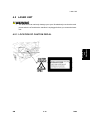
Read This First
Safety Notices
Important Safety Notices
Prevention of Physical Injury
1.
Before disassembling or assembling parts of the copier and peripherals, make sure
that the power cord is unplugged.
2.
The wall outlet should be near the copier and easily accessible.
3.
Note that some components of the copier and the paper tray unit are supplied with
electrical voltage even if the main power switch is turned off.
4.
If a job has started before the copier completes the warm-up or initializing period, keep
hands away from the mechanical and electrical components because the starts
making copies as soon as the warm-up period is completed.
5.
The inside and the metal parts of the fusing unit become extremely hot while the copier
is operating. Be careful to avoid touching those components with your bare hands.
Health Safety Conditions
Toner and developer are non-toxic, but if you get either of them in your eyes by accident, it
may cause temporary eye discomfort. Try to remove with eye drops or flush with water as
first aid. If unsuccessful, get medical attention.
Observance of Electrical Safety Standards
The copier and its peripherals must be installed and maintained by a customer service
representative who has completed the training course on those models.
Safety and Ecological Notes for Disposal
1.
Do not incinerate toner bottles or used toner. Toner dust may ignite suddenly when
exposed to an open flame.
2.
Dispose of used toner, developer, and organic photoconductors in accordance with
local regulations. (These are non-toxic supplies.)
3.
Dispose of replaced parts in accordance with local regulations.
Handling Toner
Work carefully when removing paper jams or replacing toner bottles or cartridges to
avoid spilling toner on clothing or the hands.
If toner is inhaled, immediately gargle with large amounts of cold water and move to a
well ventilated location. If there are signs of irritation or other problems, seek medical
attention.
If toner gets on the skin, wash immediately with soap and cold running water.
If toner gets into the eyes, flush the eyes with cold running water or eye wash. If there
are signs of irritation or other problems, seek medical attention.
If toner is swallowed, drink a large amount of cold water to dilute the ingested toner. If
there are signs of any problem, seek medical attention.
If toner spills on clothing, wash the affected area immediately with soap and cold water.
Never use hot water! Hot water can cause toner to set and permanently stain fabric.
Always store toner and developer supplies such as toner and developer packages,
cartridges, and bottles (including used toner and empty bottles and cartridges) out of
the reach of children.
Always store fresh toner supplies or empty bottles or cartridges in a cool, dry location
that is not exposed to direct sunlight.
Laser Safety
The Center for Devices and Radiological Health (CDRH) prohibits the repair of laser-based
optical units in the field. The optical housing unit can only be repaired in a factory or at a
location with the requisite equipment. The laser subsystem is replaceable in the field by a
qualified Customer Engineer. The laser chassis is not repairable in the field. Customer
engineers are therefore directed to return all chassis and laser subsystems to the factory or
service depot when replacement of the optical subsystem is required.
Use of controls, or adjustment, or performance of procedures other than
those specified in this manual may result in hazardous radiation exposure.
WARNING FOR LASER UNIT
WARNING: Turn off the main switch before attempting any of the procedures in the
Laser Unit section. Laser beams can seriously damage your eyes.
CAUTION MARKING:
Symbols and Abbreviations
This manual uses several symbols and abbreviations. The meaning of those symbols and
abbreviations are as follows:
See or Refer to
Clip ring
Screw
Connector
Clamp
SEF
Short Edge Feed
LEF
Long Edge Feed
PRODUCT INFORMATION
R E V I S I O N H I S T O RY
P a ge
Date
A d de d /U pd at e d /N ew
None
Product
Information
Specifications
1. PRODUCT INFORMATION
1.1 SPECIFICATIONS
See "Appendices" for the following information:
General Specifications
Supported Paper Size
Optional Equipment
SM
1-1
D096
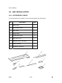
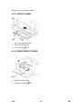
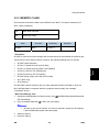
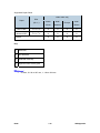
Machine Configuration
1.2 MACHINE CONFIGURATION
Unit/Component
Machine Code
Diagram
Copier (1-tray non-duplex model)
D096
[D]
Platen cover (optional)
B406
[B]
ADF (optional)
B813
[A]
Accessibility Handle Type A (optional)
B272
-
Copier
D096
1-2
SM
Product
Information
Guidance for Those Who are Familiar with Predecessor Products
1.3 GUIDANCE FOR THOSE WHO ARE FAMILIAR
WITH PREDECESSOR PRODUCTS
The D096 model is successor models to the B245 model. If you have experience with the
predecessor products, the following information will be of help when you read this manual.
Different Points from Predecessor Products
D096
B245
Duplex
Not available
Not available
Paper Tray
One tray
One tray
Printer/ Scanner
Not available
Not available
Fax
Not available
Not available
GDI Controller
Not available
Not available
GW Controller
Not available
Not available
APS (Mainframe)
Not available
Available
Copy Speed
19 cpm
15cpm
SM
1-3
D096
Overview
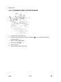
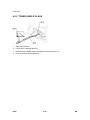
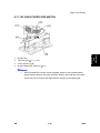
1.4 OVERVIEW
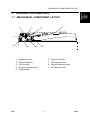
1.4.1 COMPONENT LAYOUT
D096
1-4
SM
1. 2nd Mirror
2. Exposure Lamp
3. 1st Mirror
4. Exposure Glass
5. Lens Block
6. SBU
7. Exit Sensor
8. Scanner Motor
9. Hot Roller
10. Pressure Roller
11. OPC Drum
12. Image Density Sensor
13. Registration Roller
14. Registration Sensor
SM
Product
Information
Overview
15. By-pass Tray
16. By-pass Feed Roller
17. Friction Pad
18. Paper Feed Roller
19. Paper End Sensor
20. Bottom Plate
21. PCU
22. Development Roller
23. WTL
24. Polygon Mirror Motor
25. Laser Unit
26. Toner Supply Bottle Holder
27. Exit Roller
28. 3rd Mirror
29. Scanner HP Sensor
1-5
D096
Overview
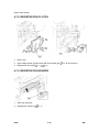
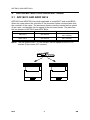
1.4.2 PAPER PATH
1.
Original Feed from ADF
2.
Paper Feed from Tray 1
3.
Paper Feed from By-pass Tray
D096
1-6
SM
Product
Information
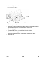
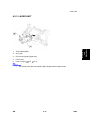
Overview
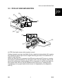
1.4.3 DRIVE LAYOUT
1. Scanner Motor
5. Development Roller
2. Main Motor
6. By-pass Feed Clutch
3. Hot Roller
7. Paper Feed Clutch
4. OPC Drum
8. Registration Clutch
SM
1-7
D096
INSTALLATION
R E V I S I O N H I S T O RY
P a ge
Date
A d de d /U pd at e d /N ew
None
Installation Requirements
2. INSTALLATION
Installation
2.1 INSTALLATION REQUIREMENTS
Before installing options, please do the following:
If there is a printer option in the machine, print out all data in the printer buffer.
Turn off the main switch and disconnect the power cord, the telephone line, and
the network cable.
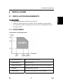
2.1.1 ENVIRONMENT
–Temperature and Humidity Chart–
Temperature Range:
10°C to 32°C (50°F to 89.6°F)
Humidity Range:
15% to 80% RH
Ambient Illumination:
Less than 1,500 lux (do not expose to direct sunlight)
Ventilation:
3 times/hr/person or more
Ambient Dust:
Less than 0.075 mg/m3 (2.0 x 10⁻⁶ oz/yd3)
SM
2-1
D096
Installation Requirements
Avoid areas exposed to sudden temperature changes:
1) Areas directly exposed to cool air from an air conditioner.
2) Areas directly exposed to heat from a heater.
Do not place the machine in areas where it can get exposed to corrosive gases.
Do not install the machine at any location over 2,000 m (6,500 ft.) above sea level.
Place the machine on a strong and level base. (Inclination on any side should be no
more than 5 mm.)
Do not place the machine where it is subjected to strong vibrations.
2.1.2 MACHINE LEVEL
Front to back:
Within 5 mm (0.2") of level
Right to left:
Within 5 mm (0.2") of level
D096
2-2
SM
Installation Requirements
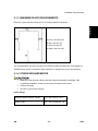
2.1.3 MINIMUM SPACE REQUIREMENTS
Installation
Place the copier near the power source, providing clearance as shown:
A (front): 750 mm (30")
B (left): 150 mm (6")
C (rear): 50 mm (2")
D (right): 250 mm (10")
The recommended 750 mm front space is sufficient to allow the paper tray to be pulled out.
Additional front space is required to allow operators to stand at the front of the machine.
2.1.4 POWER REQUIREMENTS
Make sure that the wall outlet is near the machine and easily accessible. After.
completing installation, make sure the plug fits firmly into the outlet.
Avoid multi-wiring.
Be sure to ground the machine
Input voltage:
North and South America, Taiwan:
110 – 120 V, 60 Hz, 12 A
Europe, Asia:
220 – 240 V, 50/60 Hz, 7 A
SM
2-3
D096
Copier Installation
2.2 COPIER INSTALLATION
2.2.1 POWER SOCKETS FOR PERIPHERALS
Make sure to plug the cables into the correct sockets.
[A]: Socket for ADF (Rated voltage output max. DC24 V)
[B]: Socket for paper tray unit (Rated voltage output max. DC24 V)
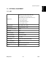
2.2.2 ACCESSORY CHECK
Check that you have the accessories in this list.
No.
Description
Q’ty
1
Multi-language (-17, -27,-19, -29)
1
2
NECR-English (-17)
1
3
Model Name Plate (-22, -19, -29)
1
4
Operating Instruction (-17, -19, -29)
1
D096
2-4
SM
Copier Installation
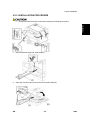
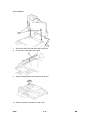
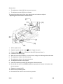
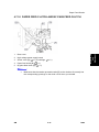
2.2.3 INSTALLATION PROCEDURE
Unplug the machine power cord before starting the following procedure.
Installation
1.
Remove filament tape and other padding.
2.
Open the front door and remove the toner bottle holder [A]
SM
2-5
D096
Copier Installation
3.
Open the right door [B], and remove the PCU (photoconductor unit) [C].
4.
Separate the PCU into the upper part and the lower part (
5.
Put a sheet of paper on a level surface and place the upper part on it.
6.
x 5).
This prevents foreign material from getting on the sleeve rollers
Distribute a pack of developer [D] to all openings equally.
Do not spill the developer on the gears [E]. If you have spilled it, remove the
developer by using a magnet or magnetized screwdriver.
D096
Do not turn the gear [E] too much. The developer may spill.
2-6
SM
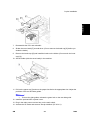
Installation
Copier Installation
7.
Reassemble the PCU and reinstall it.
8.
Shake the toner bottle [F] several times. (Do not remove the bottle cap [G] before you
shake the bottle.)
9.
Remove the bottle cap [G] and install the bottle on the holder. (Do not touch the inner
cap [H].)
10. Set the holder (with the toner bottle) in the machine.
11. Pull out the paper tray [I] and turn the paper size dial to the appropriate size. Adjust the
positions of the end and side guides.
To move the side guides, release the green lock on the rear side guide.
12. Install the optional ADF or platen cover.
13. Plug in the main power cord and turn on the main switch.
14. Activate the SP mode and execute "Devlpr Initialize" (SP 2214 1).
SM
2-7
D096
Copier Installation
15. Wait until the message "Completed" shows (about 45 seconds).
16. Activate the User Tools and select the menu "Language."
17. Specify a language. This language is used for the operation panel.
18. Load the paper in the paper tray and make a full size copy, and make sure the
side-to-side and leading edge registrations are correct.
D096
2-8
SM
Platen Cover Installation
2.3 PLATEN COVER INSTALLATION
Installation
2.3.1 ACCESSORY CHECK
Check that you have the accessories indicated below.
No.
Description
Q’ty
1
Stepped Screw
2
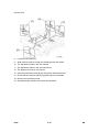
2.3.2 INSTALLATION PROCEDURE
Unplug the machine power cord before starting the following procedure.
Install the platen cover (
SM
x 2).
2-9
D096
ADF Installation
2.4 ADF INSTALLATION
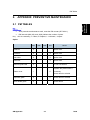
2.4.1 ACCESSORY CHECK
Check the quantity and condition of the accessories against the following list.
No.
Description
Q'ty
1
Scale Guide
1
2
DF Exposure Glass
1
3
Stud Screw
2
4
Fixing Screw
2
5
Original Size Decal
2
6
Screwdriver Tool
1
7
Attention Decal - Top Cover
1
8
Stamp Cartridge
1
9
Installation Procedure
1
D096
2-10
SM
ADF Installation
2.4.2 INSTALLATION PROCEDURE
Unplug the machine power cord before starting the following procedure.
Installation
1.
Remove the strips of tape.
2.
Remove the left scale [A] (
3.
Place the DF exposure glass [B] on the glass holder. Make sure that the white mark [C]
x 2).
is on the bottom at the front end.
4.
Peel off the backing [D] of the double-sided tape attached to the rear side of the scale
guide [E], then install the scale guide (
x 2 [removed in step 2]).
5.
Install the two stud screws [F].
6.
Mount the ADF on the copier, and then slide it to the front.
SM
2-11
D096
ADF Installation
7.
Secure the ADF unit with the fixing screws [G].
8.
Connect the cable [H] to the copier.
9.
Attach the appropriate scale decal [I] as shown.
10. Attach an attention decal to the top cover.
D096
2-12
SM
ADF Installation
The attention decals in the package are written in different languages.
Installation
11. Open the ADF [J].
12. Turn the main power switch on. Then check if the document feeder works properly.
13. Make a full size copy, and check that the side-to-side and leading edge registrations
are correct. If they are not, adjust the side-to-side and leading edge registrations. (
p.4-63).
SM
2-13
D096
Anti-condensation Heater Installation
2.5 ANTI-CONDENSATION HEATER INSTALLATION
Unplug the machine power cord before starting the following procedure.
1.
Remove the exposure glass.
2.
Remove the left cover.
3.
Pass the connector [A] through the opening [B].
4.
Install the anti-condensation heater [C], as shown.
5.
Join the connectors [A, D].
6.
Clamp the harness with the clamp [E].
7.
Reinstall the left cover and exposure glass.
D096
2-14
SM
Tray Heater
2.6 TRAY HEATER
Unplug the machine power cord before starting the following procedure.
Installation
2.6.1 TRAY HEATER
1.
Remove the 1st tray cassette [A].
2.
Remove the rear cover.
3.
Pass the connector [B] through the opening [C] and install the tray heater [D] (
SM
2-15
x 1).
D096
Tray Heater
4.
Install the relay harness [E].
5.
Fix the harness with the clamp [F].
6.
Reinstall the 1st tray cassette and the rear cover.
D096
2-16
SM
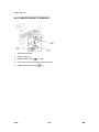
Accessibility Handle Installation
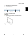
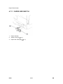
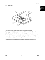
2.7 ACCESSIBILITY HANDLE INSTALLATION
Installation
The following procedure is for the paper tray for the main copier only.
1.
Remove the paper tray [A] from the main copier.
2.
Turn the paper tray over to the opposite side.
3.
Lower the paper tray grip handle [B] into the paper tray slot as shown with the arrow in
the above illustration.
SM
2-17
D096
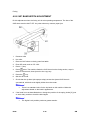
Accessibility Handle Installation
4.
Attach the grip handle to the paper tray (
5.
Put the paper tray back into the machine.
D096
x 2) as shown above.
2-18
SM
PREVENTIVE MAINTENANCE
R E V I S I O N H I S T O RY
P a ge
Date
A d de d /U pd at e d /N ew
None
PM Tables
3. PREVENTIVE MAINTENANCE
3.1 PM TABLES
Preventive
Maintenance
See "Appendices" for the "PM Tables".
SM
3-1
D096
How to Reset the PM Counter
3.2 HOW TO RESET THE PM COUNTER
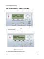
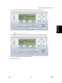
After preventive maintenance work, reset the PM counter (SP 7804 1) as follows.
1.
Activate the SP mode.
2.
Select SP 7804 1 (Reset–PM Counter).
3.
Press the OK key [A]. The message "Execute" shows.
4.
Press the button [B] below the message "Execute."
D096
3-2
SM
How to Reset the PM Counter
The messages "Execute?" followed by "Cancel" and "Execute" show.
6.
To reset the PM counter, press the button [C] below the message "Execute."
7.
Wait until the message "Completed" shows.
8.
Quit the SP mode.
Preventive
Maintenance
5.
SM
3-3
D096
REPLACEMENT AND ADJUSTMENT
R E V I S I O N H I S T O RY
P a ge
Date
A d de d /U pd at e d /N ew
None
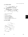
General Cautions
4. REPLACEMENT AND ADJUSTMENT
4.1 GENERAL CAUTIONS
Do not turn off the main switch while any of the electrical components are active. Doing so
may result in damage to units (such as the PCU) as they are pulled out or replaced.
4.1.1 PCU (PHOTOCONDUCTOR UNIT)
The PCU consists of the OPC drum, charge roller, development unit, and cleaning
components. Observe the following precautions when handling the PCU.
1.
Never touch the drum surface with bare hands. If the drum surface is dirty or if you
have accidentally touched it, wipe it with a dry cloth, or clean it with wet cotton and then
2.
Never use alcohol to clean the drum. Alcohol will dissolve the drum surface.
3.
Store the PCU in a cool dry place.
4.
Do not expose the drum to corrosive gases (ammonia, etc.).
5.
Do not shake a used PCU, as this may cause toner and developer to spill out.
6.
Dispose of used PCU components in accordance with local regulations.
Replacement
and
Adjustment
wipe it dry with a cloth.
4.1.2 TRANSFER ROLLER
1.
Never touch the surface of the transfer roller with bare hands.
2.
Be careful not to scratch the transfer roller, as the surface is easily damaged.
4.1.3 SCANNER UNIT
1.
Use alcohol or glass cleaner to clean the exposure and scanning glass. This will
reduce the static charge on the glass.
2.
Use a blower brush or a water-moistened cotton pad to clean the mirrors and lenses.
3.
Make sure to not bend or crease the exposure lamp’s ribbon cable.
4.
Do not disassemble the lens unit. This will cause the lens and copy image to get out of
focus.
5.
SM
Do not turn any of the CCD positioning screws. This will put the CCD out of position.
4-1
D096
General Cautions
4.1.4 LASER UNIT
1.
Do not loosen or adjust the screws securing the LD drive board on the LD unit. This will
put the LD unit out of adjustment.
2.
Do not adjust the variable resistors on the LD unit. These are adjusted at the factory.
3.
The polygonal mirror and F-theta lens are very sensitive to dust.
4.
Do not touch the toner shield glass or the surface of the polygonal mirror with bare
hands.
4.1.5 FUSING UNIT
1.
After installing the fusing thermistor, make sure that it is in contact with the hot roller
and that the roller can rotate freely.
2.
Be careful to avoid damage to the hot roller stripper pawls and their tension springs.
3.
Do not touch the fusing lamp and rollers with bare hands.
4.
Make sure that the fusing lamp is positioned correctly and that it does not touch the
inner surface of the hot roller.
4.1.6 PAPER FEED
1.
Do not touch the surface of the paper feed rollers.
2.
To avoid misfeeds, the side and end fences in each paper tray must be positioned
correctly so as to align with the actual paper size.
You must run SP 2214 to initialize the TD sensor after you install a new PCU. After
starting initialization, be sure to wait for it to reach completion (wait for the motor to
stop) before you re-open the front cover or turn off the main switch.
If the optional tray heater or optics anti-condensation heater is installed, keep the
machine's power cord plugged in even while the main switch is off, to keep the
heater(s) energized.
D096
4-2
SM
Special Tools and Lubricants
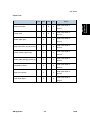
4.2 SPECIAL TOOLS AND LUBRICANTS
Part Number
SM
Description
Q’ty
Scanner Positioning Pins (4 pins/set)
1 set
A2929500
Test Chart S5S (10 pcs/set)
1 set
VSSM9000
FLUKE 87 Digital Multimeter
1
N8036701
4MB Flash Memory Card
1
A2579300
Grease Barrierta S552R
1
52039502
Grease G-501
1
4-3
Replacement
and
Adjustment
A0069104
D096
Exterior Covers & Operation Panel
4.3 EXTERIOR COVERS & OPERATION PANEL
4.3.1 REAR COVER
1.
Unplug the DF cable [A] (if installed).
2.
Rear cover [B] (
x 6)
4.3.2 COPY TRAY
1.
Copy tray [A] (
D096
x 2)
4-4
SM
Exterior Covers & Operation Panel
4.3.3 UPPER COVERS
1.
Platen Cover or ADF (if installed)
2.
Rear cover
3.
Left upper cover [A] (
4.
Front upper left cover [B] (
5.
Operation panel [C] (
6.
Right upper cover [D] (
7.
Push the cover to the rear side to release the hooks.
8.
Top rear cover [E] (
x 4,
Replacement
and
Adjustment
x 2)
x 3)
x 1)
x 1, 3 hooks)
x 1)
4.3.4 LEFT COVER
1.
SM
Left cover [A] (
x 3)
4-5
D096
Exterior Covers & Operation Panel
4.3.5 FRONT COVER
1.
Pull out the (top) paper tray.
2.
Open the front door [A].
3.
Front cover [B] (
x 4)
4.3.6 FRONT RIGHT COVER
1.
Open the front door [A].
2.
Front right cover [B] (
D096
x 1)
4-6
SM
Exterior Covers & Operation Panel
4.3.7 RIGHT REAR COVER
Right upper cover (
2.
Open the right door.
3.
Right rear cover [A] (
p.4-5 "Upper Covers")
Replacement
and
Adjustment
1.
x 1)
4.3.8 RIGHT DOOR
1.
Right rear cover (see above)
2.
Open the right door [A].
3.
Open the clamps [B] and disconnect the two connectors [C].
4.
Right door
SM
4-7
D096
Exterior Covers & Operation Panel
4.3.9 BY-PASS TRAY
1.
Right rear cover (above)
2.
Open the right door.
3.
Release the by-pass tray cable from the clamps (see [A] on the preceding procedure)
and disconnect the connector (5-pin connector with colored wires).
4.
Front-side clip ring [A]
5.
Front-side pin [B] (You can push the pin from behind the right door.)
6.
Front-side tray holder arm [C]
7.
Remove the rear-side clip ring, pin, and tray holder arm in the same manner.
8.
By-pass tray [D]
D096
4-8
SM
Exterior Covers & Operation Panel
1.
Top rear cover
2.
Platen cover sensor [A] (
SM
Replacement
and
Adjustment
4.3.10 PLATEN COVER SENSOR
x 1)
4-9
D096
Scanner Unit
4.4 SCANNER UNIT
4.4.1 EXPOSURE GLASS/DF EXPOSURE GLASS
- Exposure Glass 1.
Front upper left cover (
2.
Left scale [A] (
3.
Rear scale [B] (
4.
Exposure glass [C]
p.4-5 "Upper Covers")
x 2)
x 3)
Make sure that the mark is at the rear left corner, and that the left edge is
aligned to the support on the frame when you reinstall the exposure glass.
- DF Exposure Glass 1.
Front upper left cover (
2.
Left scale [A]
3.
DF exposure glass [D]
p.4-5 "Upper Covers")
Make sure that the mark [E] is on the bottom at the front end when reinstall the
exposure glass.
D096
4-10
SM
Scanner Unit
4.4.2 LENS BLOCK
Do not touch the paint-locked screws on the lens block. The position of the lens
assembly (black part) is adjusted before shipment.
Do not grasp the PCB or the lens assembly when you handle the lens block. The
Replacement
and
Adjustment
lens assembly may slide out of position.
p.4-10 "Exposure Glass/DF Exposure Glass ")
1.
Exposure glass (
2.
Lens cover [A] (
3.
Disconnect the flat cable [B].
4.
Lens block [C] (
x 5)
x 4).
Adjust the image quality (
p.4-58 "Copy Adjustments Printing/Scanning")
after you install a new lens block.
SM
4-11
D096
Scanner Unit
4.4.3 LAMP STABILIZER BOARD AND EXPOSURE LAMP
1.
Operation panel (
p.4-5 "Upper Covers")
2.
Exposure glass (
p.4-10 "Exposure Glass/DF Exposure Glass ")
3.
Slide the first scanner to a position where the front end of the lamp is visible.
4.
Place one hand under the lamp stabilizer board [A] and release the hook [B].
5.
Lamp stabilizer board (
6.
Press the plastic latch [C] and push the front end of the lamp toward the rear.
7.
Lamp [D] (with the cable)
D096
x 2)
4-12
SM
Scanner Unit
1.
Left upper cover, front upper left cover, operation panel, top rear cover (
p.4-10
"Exposure Glass/DF Exposure Glass ")
p.4-10 "Exposure Glass/DF Exposure Glass ")
2.
Exposure glass (
3.
Scanner motor [B] ( x 3,
x 1, 1 spring, 1 belt)
Install the belt first, and then set the spring when you reassemble. Fasten the
leftmost screw (viewed from the rear), and fasten the other two screws.
SM
Adjust the image quality after you install the motor.
4-13
D096
Replacement
and
Adjustment
4.4.4 SCANNER MOTOR
Scanner Unit
4.4.5 SCANNER HOME POSITION SENSOR
1.
Left upper cover, top rear cover.
2.
Exposure glass, DF exposure glass (if installed) (
p.4-10 "Exposure Glass/DF
Exposure Glass ")
3.
Disconnect the connector [A].
4.
Scanner left lid [B] (
5.
Sensor tape [C].
6.
Scanner home position sensor [D]
D096
x 7)
4-14
SM
Scanner Unit
4.4.6 ADJUSTING SCANNER POSITIONS
Grasp the front and rear ends (not the middle) of the first scanner when you
manually move it. The first scanner may be damaged if you press, push, or pull its
middle part.
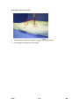
- Overview Adjust the scanner positions when the first scanner [C] and second scanner [B] are not
parallel with the side frames [A], or, when you have replaced one or more of the scanner
Replacement
and
Adjustment
belts.
To adjust the scanner positions, do either of the following:
To adjust the belt contact points on the first scanner (See "Adjusting the First Scanner
Contact Points" below.)
To adjust the belt contact points on the scanner bracket (See "Adjusting the Second
Scanner Contact Points" below.)
The two actions above have the same objectives--to align the following holes and marks:
SM
The adjustment holes [H] [J] in the first scanner
4-15
D096
Scanner Unit
The adjustment holes [H] [J] in the second scanner
The alignment marks [G] [I] on the frames
The scanner positions are correct when these holes and marks are aligned.
- Adjusting the First Scanner Contact Points -
1.
ADF or platen cover
2.
Operation panel, top rear cover (
3.
Exposure glass (
4.
Loosen the 2 screws [A] [F].
5.
Slide the 1st and 2nd scanners, or one of them, to align the following holes and marks
6.
The adjustment holes in the first scanner
7.
The adjustment holes in the second scanner
8.
The alignment marks on the frames
9.
Insert the positioning tools [D] [E] through the holes and marks.
p.4-5 "Upper Covers").
p.4-10 "Exposure Glass/DF Exposure Glass ")
10. Check that the scanner belts [B] [C] [G] [H] are properly set between the bracket and
the 1st scanner.
11. Tighten the screws [A] [F].
12. Remove the positioning tools.
13. Reassemble the machine and check the operation.
D096
4-16
SM
Scanner Unit
- Adjusting the Second Scanner Contact Points -
1.
ADF or platen cover
2.
Operation panel, top rear cover (
3.
Exposure glass (
4.
Controller bracket [A] (
5.
Disconnect the platen-cover-sensor connector [B].
6.
Rear frame [C] (
7.
Scale bracket [D] (
SM
p.4-5 "Upper Covers").
Replacement
and
Adjustment
p.4-10 "Exposure Glass/DF Exposure Glass ")
x 3)
x 7)
x 2)
4-17
D096
Scanner Unit
8.
Loosen the 2 screws [A].
9.
Slide the 2nd scanner to align the following holes and marks
10. The adjustment holes in the first scanner
11. The adjustment holes in the second scanner
12. The alignment marks on the frames
13. Insert the positioning tools [B] [C] through the holes and marks.
14. Check that the scanner belts are properly set in the brackets.
15. Remove the positioning tools.
16. Reassemble the machine and check the operation.
D096
4-18
SM
Laser Unit
4.5 LASER UNIT
The laser beam can seriously damage your eyes. Be absolutely sure that the main
power switch is off and that the machine is unplugged before you access the laser
unit.
Replacement
and
Adjustment
4.5.1 LOCATION OF CAUTION DECAL
SM
4-19
D096
Laser Unit
4.5.2 TONER SHIELD GLASS
1.
Open the front door.
2.
Lift the toner cartridge latch [A].
3.
Press the toner shield glass cover [B] to the left and pull it out.
4.
Pull out the toner shield glass [C].
D096
4-20
SM
Laser Unit
1.
Toner shield glass.
2.
Copy tray
3.
Pull out the (upper) paper tray.
4.
Front cover
5.
Laser unit [A] (
SM
x 2,
Replacement
and
Adjustment
4.5.3 LASER UNIT
x 4)
The screw at the left front position [B] is longer than the other three.
4-21
D096
Laser Unit
4.5.4 LD UNIT
Do not touch the paint-locked screw [A]. The LD position is adjusted before
shipment.
1.
Laser unit
2.
LD unit [B] (
D096
x 1)
Do not screw the LD unit in too tightly when you install it.
4-22
SM
Laser Unit
Replacement
and
Adjustment
4.5.5 POLYGONAL MIRROR MOTOR
1.
Laser unit
2.
Two rubber bushings [A]
3.
Laser unit cover [B] (
4.
Polygonal mirror motor [C] (
5.
After reassembling, adjust the image quality (
x 1)
x 4)
p.4-58 "Copy Adjustments
Printing/Scanning").
SM
4-23
D096
Laser Unit
4.5.6 LASER UNIT ALIGNMENT ADJUSTMENT
Reinstall the copy exit tray before you turn the main switch on. The laser beam
may go out of the copier when the copy exit tray is not installed. The laser beam
can seriously damage your eyes.
1.
Start the SP mode.
2.
Select SP 5902 1 and output the ‘Trimming Area’ pattern (pattern 10).
3.
Make sure that the four corners of the pattern make right angles:
4.
If they make right angles, you do not need to adjust the laser unit alignment.
If they do not make right angles, go on to the next step.
Check the screw position on the lever [B].
If the screw is in the hole [C], go on to the next step.
If the screw is in the slot [D], loosen the screw on the lever, loosen the four screws
on the laser unit, and go on to step 9.
The initial position of the screw is in hole [C].
5.
Four screws in the laser unit (
6.
Remove the lever (
p.4-21)
x 1), confirm the position of the hole beneath the slot [D], and
reinstall the lever.
7.
Install the screw (through the slot [D]) loosely into the hole beneath the slot (do not
tighten the screw).
8.
Install the four screws for the laser unit loosely (do not tighten the screws).
9.
When you rotate the lever clockwise or counterclockwise by one notch of the lever, the
D096
4-24
SM
Laser Unit
corners of the pattern shift by ±0.4 mm (from the leading and trailing edges). See the
trim pattern made in step 2, and find how much the corners should be shifted.
10. Tighten the screw [A].
11. Tighten the screws on the laser unit.
12. Reinstall the copy tray.
13. Print the trim pattern and check the result. Do the procedure again if further adjustment
SM
Replacement
and
Adjustment
is required.
4-25
D096
PCU Section
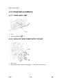
4.6 PCU SECTION
4.6.1 PCU
1.
Toner bottle with the holder [A]
2.
Open the right door.
3.
Press the latch [B] and pull out the PCU [C].
Do not touch the OPC drum surface with bare hands.
p.4-32).
4.
Load new developer (
5.
Do SP 2214 to reinitialize the TD sensor when you reassemble.
D096
4-26
SM
PCU Section
4.6.2 TONER SUPPLY MOTOR
1.
Copy tray (
2.
Open the front door.
3.
Toner bottle holder (
4.
Toner supply motor [A] (
SM
Replacement
and
Adjustment
p.4-5 "Upper Covers")
p.4-26 "PCU")
x 1)
4-27
D096
PCU Section
4.6.3 PICK-OFF PAWLS AND TONER DENSITY SENSOR
Do not turn the PCU upside down. This causes toner and developer to spill out.
1.
PCU (
2.
Pawl [A]
3.
p.4-26)
Pull down the pawl and release the bottom end.
Toner density sensor [B] (
x 1)
The toner density sensor is taped to the bottom of the PCU. Pry it off with a
regular screwdriver.
4.
After reinstalling the pick-off pawls or toner density sensor, adjust the image quality
(
D096
p.4-33 "After Replacement or Adjustment").
4-28
SM
PCU Section
Replacement
and
Adjustment
4.6.4 OPC DRUM
p.4-26)
1.
PCU (
2.
Front side piece [A] (
x 1)
3.
Rear side piece [B] (
x 2, 1 coupling)
4.
Separate the drum section [C] from the developer section [D].
To ensure that the left-side gears line up, keep the drum cover [E] closed
when reinserting the front side piece.
5.
Pry out the drum retaining clip [F].
Install the clip in the same orientation (with the lip facing away from the drum
shaft) when you reassemble.
6.
OPC drum [G]
7.
When reassembling, adjust the image quality (
p.4-33 "After Replacement or
Adjustment").
SM
4-29
D096
PCU Section
4.6.5 CHARGE ROLLER AND CLEANING BRUSH
p.4-29)
1.
OPC Drum (
2.
Holding pin [A]
3.
Stepped screw [B]
4.
Charge roller [C] and cleaning brush [D] (with the holders and springs)
5.
Turn the gear [E] (as necessary) so that the rear holder [F] comes out.
When reassembling, adjust the image quality (
p.4-33 "After Replacement or
Adjustment").
D096
4-30
SM
PCU Section
4.6.6 CLEANING BLADE
1.
Drum charge roller (
2.
Cleaning blade [B] (
3.
When reassembling, adjust the image quality (
p.4-30 "Charge Roller and Cleaning Brush")
Replacement
and
Adjustment
x 2)
p.4-33 "After Replacement or
Adjustment").
Apply toner to the edge of the new cleaning blade when you replace the cleaning
blade. This prevents possible damage to the OPC drum and blade.
After installing the cleaning blade, remove some of the toner from the old blade
with your finger.
Apply the toner to the edge [A] of the new cleaning blade. Make sure to apply the
toner evenly along full length of the new cleaning blade.
SM
4-31
D096
PCU Section
4.6.7 DEVELOPER
p.4-26)
1.
PCU (
2.
To let the toner fall to the development section, gently tap about eight different spots on
the top of the PCU with a screwdriver. Each spot must be approximately at an equal
distance from the next spot.
3.
Reinstall the PCU in the copier.
4.
Turn the main switch on.
5.
Open and close the front door and wait for the machine to rotate the development roller
for about 10 seconds.
6.
Repeat the previous step two more times.
7.
PCU (
8.
Separate the developer section from the OPC drum section (
9.
Top part [A] of the development unit (
p.4-26)
p.4-29).
x 5)
Release the hook [B].
10. Set the coupling [C] back to the shaft.
11. Turn the coupling in the direction of the arrow [D] to remove developer from the roller.
12. Turn the bottom part [E] over and rotate the gears to remove the developer.
13. Load new developer.
14. When reassembling, execute SP 2214 to reinitialize the TD sensor.
D096
4-32
SM
PCU Section
Make sure no toner or developer stays on the gear. Clean the gears as
necessary with a blower brush, etc.
Be sure to replace the Mylar at the rear side in the correct position. (The Mylar
protects the gears at the rear side from falling toner).
4.6.8 AFTER REPLACEMENT OR ADJUSTMENT
Do the following procedure after replace or adjust any of the PCU components.
This procedure is not necessary when you replaced the whole PCU with a new
one.
1.
Take 5 sample copies.
2.
If black dots (dropped toner) show on any of the copies, continue as follows. (If all
3.
Remove the PCU from the mainframe.
4.
Tap the top of the PCU with a screwdriver at eight evenly spaced locations (two or
Replacement
and
Adjustment
copies are clean, you don't need to do the following steps.)
three taps at each spot), to knock the recycled toner down into the development
section.
5.
Put the PCU back into the mainframe.
6.
Turn the main power on. Then open and close the door and wait for the machine to
rotate the development roller for 10 seconds. Then open and close the door two more
times, so that total rotation time is 30 seconds.
7.
Make some sky-shot copies (or solid black prints).
If using A4 or 81/2" x 11" paper, make 4 copies/prints.
If using A3 or 11" x 17" paper, make 2 copies/prints.
To make solid black prints, use SP 5902 pattern 8.
Step 7 is required only after parts replacement or adjustment. You do not need
to make sky-shot (or solid black) copies after you replace the developer.
SM
4-33
D096
Paper Feed Section
4.7 PAPER FEED SECTION
4.7.1 PAPER FEED ROLLER
1.
Paper cassette
2.
Clip [A]
3.
Push the shaft back through the opening, and tilt it up.
If the black plastic bushing [B] comes off, make sure you remount it when
reinstall the shaft.
4.
Paper feed roller [C]
D096
4-34
SM
Paper Feed Section
1.
Paper cassette
2.
Clip [A]
3.
Push the shaft back through the opening, so that the roller moves clear of the friction
pad.
4.
Friction pad [B]
4.7.3 PAPER END SENSOR
1.
Paper cassette
2.
Paper end sensor [A] (
SM
x 1)
4-35
D096
Replacement
and
Adjustment
4.7.2 FRICTION PAD
Paper Feed Section
4.7.4 EXIT SENSOR
1.
Open the right door.
2.
Front right cover
3.
Guide [A] (
4.
Exit sensor bracket [B] (
5.
Exit sensor [C] (
D096
x 2)
x 1)
x 1)
4-36
SM
Paper Feed Section
1.
Replacement
and
Adjustment
4.7.5 BY-PASS FEED ROLLER AND PAPER END SENSOR
By-pass tray
If you have a support to keep the by-pass tray within the reach of the
connector cable, you do not need to disconnect the connector. When you do
so, use caution not to place too much load on the cable.
2.
Sensor holder [A]
3.
By-pass paper end sensor [B] (
4.
By-pass feed roller [C]
SM
x 1)
4-37
D096
Paper Feed Section
4.7.6 REGISTRATION ROLLER
1.
PCU
2.
Front cover
3.
Right door
4.
Rear cover
5.
High-voltage power supply
6.
Registration clutch
7.
Unhook the springs [A] and [B] at the rear and front sides.
8.
Guide support [C] and guide [D] (
9.
Bushing [E] (
x 1,
x 1)
x 1)
10. Gear [F] and bushing [G] (
x 1)
11. Registration roller [H] with the image transfer unit [I]
D096
4-38
SM
Paper Feed Section
1.
By-pass tray
2.
Tray lever [A] (
3.
Lift the upper tray [B]
4.
By-pass paper size switch [C] ( x 1)
Replacement
and
Adjustment
4.7.7 BY-PASS PAPER SIZE SWITCH
x 1, 1 pin)
When reinstalling the switch: Move the paper guides to their middle position
(about halfway between fully open and fully closed), and install the round gear
so that the hole in the gear [D] aligns with the peg [E] on the sliding gear.
SM
4-39
D096
Paper Feed Section
4.7.8 REGISTRATION CLUTCH
1.
Rear cover
2.
High-voltage power supply board (with the bracket) [A] (
3.
Registration clutch [B] (
x 1,
x 4, all connectors)
x 1)
4.7.9 REGISTRATION SENSOR
1.
Open the right door.
2.
Registration sensor [A] (
D096
x 1)
4-40
SM
Paper Feed Section
1.
Rear cover
2.
High-voltage power supply board
3.
Clutch cover [A] (
4.
Paper feed clutch [B] (
5.
By-pass feed clutch [C] (
x 2, 2 bushings,
Replacement
and
Adjustment
4.7.10 PAPER FEED CLUTCH AND BY-PASS FEED CLUTCH
x2)
x 1)
x 1)
Make sure that the rotation-prevention tabs [D] on the clutches fit correctly into
the corresponding openings on the clutch cover when you reinstall.
SM
4-41
D096
Paper Feed Section
4.7.11 PAPER SIZE SWITCH
1.
Paper cassette
2.
Switch cover [A] (
3.
Paper size switch [B] (
D096
x 1)
x 1)
4-42
SM
Image Transfer
4.8 IMAGE TRANSFER
4.8.1 IMAGE TRANSFER ROLLER
Do not touch the transfer roller surface with bare hands
Replacement
and
Adjustment
1.
Open the right door.
2.
Lift the plastic holders [A] with the image transfer roller [B].
Leave the springs under the holders. Make sure that the pegs [C] on the
holders [D] engage with the springs when you reassemble.
SM
4-43
D096
Image Transfer
4.8.2 IMAGE DENSITY SENSOR
1.
Open the right door.
2.
Plastic cover [A]
3.
Image transfer roller (
4.
Push down on the notch [B] to free the sensor.
5.
Image density sensor [C] (
D096
p.4-43)
x 1)
4-44
SM
Fusing
4.9 FUSING
4.9.1 FUSING UNIT
The fusing unit can become very hot. Make sure that it has cooled down
Replacement
and
Adjustment
sufficiently before you handle it.
1.
Turn off the main switch, and unplug the machine.
2.
Front right cover
3.
Open the right door.
4.
Fusing unit [A] (
x 2,
x 4)
4.9.2 THERMISTOR
1.
Fusing unit (see above)
2.
Thermistors [A] (
SM
x 1,
x 1)
4-45
D096
Fusing
4.9.3 FUSING LAMPS
1.
Fusing unit
2.
Separate the hot roller section [A] from the pressure roller section [B] (
3.
Front holding plate [C] (
x 1)
4.
Rear holding plate [D] (
x 1)
5.
Fusing lamp with the connector (600W) [E] (
x 2)
6.
Fusing lamp with the connector (550W) [F] (
x 2)
x 4).
Check that the front ends of the two lamps fit in the front holding plate when
you reassemble. They do not fit in there if you arrange the two lamps
incorrectly.
D096
4-46
SM
Fusing
4.9.4 HOT ROLLER STRIPPER PAWLS
1.
Hot roller section (See above)
2.
Roller guard [A] (
3.
Metal holders [B] (1 holder for each)
4.
Hot roller stripper pawls [C] (1 spring for each)
Replacement
and
Adjustment
x 3)
4.9.5 HOT ROLLER
1.
Hot roller stripper pawls (See above)
2.
Hot roller [A] (2 C-rings, 1 gear, 2 bearings)
SM
4-47
D096
Fusing
4.9.6 THERMOSTAT
1.
Hot roller (See above)
2.
Thermostat [A] (
D096
x 2 for each)
4-48
SM
Fusing
Replacement
and
Adjustment
4.9.7 PRESSURE ROLLER AND BUSHINGS
1.
Separate the hot roller section from the pressure roller section (
p.4-46 "Fusing
Lamps").
2.
Fusing entrance guide [A] (
3.
2 springs [B]
4.
2 pressure arms [C]
5.
2 Bushings [D]
6.
Pressure roller [E]
SM
x 2)
4-49
D096
Fusing
4.9.8 NIP BAND WIDTH ADJUSTMENT
Do this adjustment when the fusing unit is at its operating temperature. The size of the
OHP sheet must be A4/LT LEF. Any other sizes may cause a paper jam.
1.
Pressure roller
2.
Hot roller
1.
Place an OHP sheet on the by-pass feed table.
2.
Enter SP mode, and run SP 1109.
3.
Press '1' (Yes)
4.
Press
twice. The machine feeds the OHP sheet into the fusing section, stops it
there for 20 seconds, then ejects it to the copy tray.
key.
5.
Press the
6.
Quit the SP mode.
7.
Check that the nip band (the opaque stripe) across the ejected OHP sheet is
symmetrical, with both ends slightly thicker than the center.
There is no standard value for the nip band on this machine. Make the
adjustment based on the band's appearance.
8.
If the band is not as described above, change the position of the spring hooks [C] (one
on each side), and then check the band again.
D096
The higher hook position produces greater tension.
4-50
SM
Fusing
4.9.9 CLEANING ROLLER
Pressure roller and bushings (
2.
Cleaning roller [A]
p.4-49)
Replacement
and
Adjustment
1.
SM
4-51
D096
Other Replacements
4.10 OTHER REPLACEMENTS
4.10.1 QUENCHING LAMP
1.
PCU
2.
Quenching lamp [A] (
x 1)
4.10.2 HIGH-VOLTAGE POWER SUPPLY BOARD
1.
Rear cover
2.
High-voltage power supply board [A] (
D096
x 2, 3 standoffs, all connectors)
4-52
SM
Other Replacements
1.
Rear cover
2.
BICU [A] (
Replacement
and
Adjustment
4.10.3 BICU (BASE-ENGINE IMAGE CONTROL UNIT)
x 7, all connectors, 2 flat cables)
Remove the NVRAM [B] from the old BICU and install it on the new BICU
when you replace the BICU. The NVRAM keeps machine-specific data.
4.10.4 MAIN MOTOR
1.
Rear cover
2.
Main motor [A] (
SM
x 4,
x 1)
4-53
D096
Other Replacements
4.10.5 LEFT EXHAUST FAN
1.
Rear cover
2.
Left cover
3.
Fan cover [A] (
4.
Fan [B] (
x 3,
x 3)
x 1)
Make sure that the arrow on the fan [C] points the outside of the copier when you
reassemble. The arrow indicates the direction of the air current.
4.10.6 PSU (POWER SUPPLY UNIT)
1.
Left cover
2.
PSU [A] (All connectors,
D096
x 6)
4-54
SM
Other Replacements
Replacement
and
Adjustment
4.10.7 GEARBOX
- Replacement Procedure 1.
Inverter tray [A]
2.
Two screws [B] from the middle rear cover
This step releases the topmost part of the BICU bracket.
3.
High-voltage power supply board (with the bracket) (
4.
BICU (with the bracket) [C] (
p.4-40)
x 6)
If you have difficulty to remove the bracket, remove the screw at the middle of
the crosspiece (see step 6).
5.
Main motor
6.
Crosspiece [D] (
7.
Registration clutch
SM
x 3)
4-55
D096
Other Replacements
8.
PCU
9.
This step releases the gear (on the gearbox) that drives the PCU.
Ground plate [E] (
10. Gearbox [F] (
x 2)
x 5, 1 belt)
Do not change the position of the spring [G] and make sure that the bushing [H] on the
PCU drive shaft is in the correct position you when you reassemble. You can adjust its
position by rotating the gear [I] seen from the opening of the gearbox.
- Gear Arrangement in the Gearbox -
D096
4-56
SM
The gears are numbered 1 to 12 in the order in which they are to be installed in the gearbox.
These numbers show both on the gearbox and on the front (exposed) surface of each gear.
If the gears fall out, start by finding gear number 1 and installing it onto location number 1
(setting it into place so that the side with the printed number stays visible). Then install the
remaining gears (2 to 12) in the same way.
SM
4-57
D096
Replacement
and
Adjustment
Other Replacements
Copy Adjustments Printing/Scanning
4.11 COPY ADJUSTMENTS PRINTING/SCANNING
You need to perform the adjustment after you do a Memory All Clear, and after you
replace or adjust any of the following parts.
First or second scanner
Lens Block
Scanner Motor
Polygonal Mirror Motor
Paper Tray
Paper Side Fence
For detailed explanations about how to access and use the SP modes, see
Section 5.
D096
4-58
SM
Copy Adjustments Printing/Scanning
4.11.1 PRINTING
Make sure the paper is installed correctly in each paper tray before you start these
adjustments.
Use the Trimming Area Pattern (SP 5902, No.10) to print the test pattern for the
printing adjustments below.
Set SP 5902 to 0 again after you complete these printing adjustments.
- Registration - Leading Edge/Side-to-Side 1.
Check the leading edge registration for each paper feed station, and adjust each of
these registrations using SP 1001.
2.
Check the side-to-side registration for each paper feed station, and adjust these
Tray
SP mode
All Trays
SP 1001 1
By-pass feed
SP 1001 2
1st tray
SP 1002 1
By-pass feed
SP 1002 5
Replacement
and
Adjustment
registrations using SP 1002.
Specification
2 ± 1.5 mm
A: Leading Edge Registration
B: Side-to-side Registration
- Blank Margin -
SM
4-59
D096
Copy Adjustments Printing/Scanning
If the leading edge or side-to-side registration cannot be adjusted to within the
specification, then adjust the leading-edge blank margin or the left-side blank
margin.
1.
Check the trailing edge and right side edge blank margins, and adjust them using the
following SP modes.
SP mode
Trailing edge
SP 2101 2
Right edge
SP 2101 4
Leading edge
SP 2101 1
Left edge
SP 2101 3
Specification
2 +2.5/–1.5 mm
2 ± 1.5 mm
A: Trailing Edge Blank Margin
B: Right Edge Blank Margin
C: Leading Edge Blank Margin
D: Left Edge Blank Margin
- Main Scan Magnification 1.
Print the single-dot grid pattern (SP 5902 1).
2.
Check the magnification (the grid size should be 2.7 x 2.7 mm), and if necessary use
SP 2998 to adjust it. The specification is 100 ± 1%.
4.11.2 SCANNING
D096
4-60
SM
Copy Adjustments Printing/Scanning
Before doing the following scanner adjustments, check and adjust the printing
leading-edge and side-to-side registrations and the printing blank margins (as
described above).
Use an A3 test chart to perform the following adjustments.
- Registration: Platen Mode 1.
Place the test chart on the exposure glass and make a copy from one of the feed
stations.
2.
Check the leading edge and side-to-side registration, and adjust as necessary with the
following SP modes.
SP mode
Leading edge
Specification
SP 4010
2 ± 1.5 mm
SP 4011
Replacement
and
Adjustment
Side-to-side
A: Leading edge registration
B: Side-to-side registration
- Magnification -
A: Main scan magnification
B: Sub-scan magnification
SM
4-61
D096
Copy Adjustments Printing/Scanning
- Main Scan Magnification 1.
Place the A3 test chart on the exposure glass and make a copy from one of the feed
stations.
2.
Check the magnification ratio. If necessary, adjust the magnification using the following
SP mode.
SP mode
Main Scan Magnification
SP 4009
Specification
± 1.0%
- Sub-Scan Magnification 1.
Place the OS-A3 test chart on the exposure glass and make a copy from one of the
feed stations.
2.
Check the magnification ratio. If necessary, adjust the magnification with the following
SP mode.
SP mode
Sub-scan magnification
SP 4008
Specification
± 1.0%
- Standard White Density Adjustment This procedure adjusts the standard white density level. Do this adjustment after you do
any of the following:
After you replace the standard white plate.
After you replace the NVRAM on the BICU. (But note that you do not need to carry out
this adjustment if you have replaced the BICU itself but retained the previous NVRAM
board [by moving it over onto the new BICU].)
After you perform a memory all clear (SP 5801 2)
Procedure:
1.
Place 10 sheets of new A4/LTR paper (sideways, LEF) or new A3/DLT paper on the
exposure glass, and close the platen cover or the ADF.
2.
Enter SP 4428 1 and select "1: YES". The machine automatically adjusts the standard
white density.
D096
4-62
SM
Copy Adjustments Printing/Scanning
4.11.3 ADF IMAGE ADJUSTMENT
A: Leading edge registration
B: Side-to-side registration
Place the temporary test chart on the ADF and make a copy from one of the feed
stations.
2.
Check the registrations, and adjust as necessary with the appropriate SP modes, as
follows.
SP mode
Side-to-side registration
SP 6006 1
Leading edge registration
SP 6006 2
Blank margin for the trailing edge
SP 6006 3
SM
4-63
D096
Replacement
and
Adjustment
1.
Make a temporary test chart as shown above, using A3/11" x 17" paper.
Copy Adjustments Printing/Scanning
- Sub-scan Magnification -
A: Sub-scan magnification
Make a temporary test chart as shown above, with A3/11" x 17" paper.
Place the temporary test chart on the ADF and make a copy from one of the feed stations.
Check the registration, and if necessary adjust it with SP 6006 5. The specification is
±1.0%.
D096
4-64
SM
SERVICE TABLES
R E V I S I O N H I S T O RY
P a ge
Date
A d de d /U pd at e d /N ew
None
Service Program Mode
5. SERVICE TABLES
5.1 SERVICE PROGRAM MODE
Do not let the user access the SP mode. Only service representatives are allowed
to access the SP mode. The machine quality or its operation is NOT guaranteed if
persons other than service representatives accesses the SP mode.
5.1.1 SP TABLES
See "Appendices" for the following information:
System SP Tables
5.1.2 HOW TO ENTER THE SP MODE
The following two modes are available:
SP Mode (Service Program Mode): The SP Mode includes the programs that are
Service
Tables
necessary for standard maintenance work.
SM
5-1
D096
Service Program Mode
Starting SP Mode
Selecting Programs
When a blinking underscore (or several blinking underscores) shows, you can type a
number from the numeric keypad [D].
When the sign "
/OK" [A] shows in the upper right corner, you can scroll through the
menu by pressing the left-arrow key [B] or the right-arrow key [C]. To select a program,
press the "OK" key [F].
Specifying Values
After locating a program, press the "OK" key. A blinking underscore (or several blinking
underscores) indicates which value you can change. The value in parentheses is the
default value of the menu.
Type a necessary value from the numeric keypad. To switch between positive (plus)
and negative (minus) values, press the [./*] (period/asterisk) key.
To validate the value, press the "OK" key. To cancel the value, press the cancel key [E].
Activating Copy Mode
You can activate the copy mode while the SP mode is running. When you do so, the copier
outputs images or patterns that help you adjust the SP-mode program.
Press the
Specify copy settings and press the "OK" key.
To return to the SP mode, press the
key. The copy mode is activated.
key.
You cannot end the SP mode while the copy mode is activated.
Quitting Programs/Ending (S)SP Mode
Press the
key or the "Cancel" key to quit the program. You can end the SP mode by
pressing one of these keys several times.
D096
5-2
SM
Using SP Modes
5.2 USING SP MODES
5.2.1 ADJUSTING REGISTRATION AND MAGNIFICATION
To adjust the registration and magnification, you need to use several service programs.
The chart shows an example of the procedure to adjust the machine in the basic
Service
Tables
configuration.
SM
5-3
D096
Using SP Modes
5.2.2 ID SENSOR ERROR ANALYSIS (SP 2221)
The image quality may become very bad when the ID sensor does not operate properly.
However, there is no such SC code that indicates ID-sensor malfunction; instead, SP 2221
shows you some information on the ID sensor. Check this information when the image
quality is not very good.
The table lists the information shown with SP 2221 (ID Sensor Error Analysis).
SP
Error condition
Possible cause
SP 2221 1 Vsg
Vsg < 2.5V or
ID sensor defective
(VG in the display) (Vsg – Vsp) <
ID sensor dirty
1.00V
Drum not charged
SP 2221 2 Vsp
Vsp > 2.5V or
Toner density very low
(VP in the display)
(Vsg – Vsp) <
ID sensor pattern not
1.00V
created
SP 2221 3 Power
Vsg < 3.5V
(PW in the
when maximum
display)
power (979) is
applied
SP 2221 4 Vsdp
Remarks
ID sensor defective
ID sensor dirty
Drum not get charged
Power source for the
ID-sensor light
No Error
Conditions
SP 2221 5 Vt
Vt > 4.5V or
Vt < 0.2V
TD sensor defective
SP 2221 6 Vts
D096
5-4
SM
Using SP Modes
5.2.3 MEMORY CLEAR
This machine stores all the data in the NVRAM on the BICU. The data is cleared by SP
5801 2 (see exceptions)
002
Main Motor Reverse
003
Quenching Lamp
Data
All data
NVRAM
Cleared by
BICU
Remarks
SP 5801 2
- Exceptions SP 5801 2 clears most of the settings and counters stored in the NVRAM on the BICU (the
values return to their default values). However, the following settings are not cleared:
SP 5807 (Area Selection)
SP 5811 1 (Serial Num Input [Code Set])
SP 5811 3 (Serial Num Input [ID2 Code Display])
SP 5812 1 (Service TEL [Telephone])
SP 5812 2 (Service TEL [Facsimile])
SP 5907 (Plug & Play: Not used in this model)
SP 7 (Data Log)
SP 8 (History)
Service
Tables
Use SP 5802 2 (basic machine) after you have replaced the BICU NVRAM or when the
BICU NVRAM data is corrupted. When the program ends normally, the message
"Completed" shows.
- With Flash Memory Card
1.
Upload the NVRAM data to a flash memory card (
NVRAM Data Upload/Download
(SP 5824/5825)).
2.
Print out all SMC data lists (
SMC Print (SP 5990)).
Be sure to print out all the lists. You have to manually change the SP settings
if the NVRAM data upload ends abnormally.
3.
Select SP 5801 2.
4.
Press the OK key.
SM
5-5
D096
Using SP Modes
5.
Select "Execute." The messages "Execute?" followed by "Cancel" and "Execute"
shows.
6.
Select "Execute."
7.
When the program has ended normally, the message "Completed" shows. If the
program has ended abnormally, an error message shows.
8.
Press the cancel key.
9.
Turn the main switch off and on.
10. Download the NVRAM data from a flash memory card (
NVRAM Data
Upload/Download (SP 5824/5825))
- Without Flash Memory Card 1.
Print out all SMC data lists (
2.
Select SP 5-801.
3.
Press the OK key.
4.
Select "Execute." The messages "Execute?" followed by "Cancel" and "Execute"
SMC Print (SP 5990)).
show.
5.
Select "Execute."
6.
When the program has ended normally, the message "Completed" is displayed. If the
program has ended abnormally, an error message shows.
7.
Turn the main switch off and on.
8.
Adjust the printer and scanner registration and magnification (
p.4-58 "Copy
Adjustments Printing/Scanning").
9.
Refer to the SMC lists, and enter any values that differ from the factory settings.
Double-check the values for SP 4901.
10. Adjust the standard white level (SP 4428).
11. Initialize the TD sensor (SP 2214).
12. Check the copy quality and the paper path.
D096
5-6
SM
Using SP Modes
5.2.4 INPUT CHECK (SP 5803)
- Conducting an Input Check 1.
Select SP 5803.
2.
Select the number (see the table below) corresponding to the component.
3.
Select "Execute." The copy mode is activated.
4.
The sign "01H" or "00H" show (see the table below).
- Input Check Table -
Sensor/Switch
01H
00H
001
Safety SW
Open
Closed
002
Safety SW-LD 5V
Open
Closed
003
Right Cover SW
Open
Closed
004
Right Low Cover SW
Open
Closed
005
Tray Cover SW
Open
Closed
006
Upper Relay S
Paper detected
Not detected
007
Lower Relay S
Paper detected
Not detected
008
Vertical Trans S
Paper detected
Not detected
009
Registration Sensor
Paper detected
Not detected
010
Exit Sensor
Paper detected
Not detected
011
Duplex Inverter S
Paper detected
Not detected
012
Duplex Entrance S
Paper detected
Not detected
013
Duplex Exit S
Paper detected
Not detected
014
By-pass PE S
Paper detected
Not detected
015
By-pass P Size S
*1
016
Upper PE S
Paper detected
SM
5-7
Service
Tables
Num.
Not detected
D096
Using SP Modes
Num.
Sensor/Switch
01H
00H
017
Lower PE S
Paper detected
018
Upper P Size SW
*1
019
Lower P Size SW
*1
020
BK-Upper Paper End S
Paper detected
Not detected
021
BK-Lower Paper End S
Paper detected
Not detected
022
BK-Up P Size SW
*1
023
BK-Low P Size SW
*1
024
BK-Up P Height S
*2
025
BK-Low P Height S
*2
026
BK-Upper Lift S
At upper limit
028
BK type
*3
030
Duplex Installed
Installed
Not installed
031
Lower Lift S
At upper limit
Not at upper limit
032
Main M Lock
Locked
Not locked
033
Polygon M Lock
Locked
Not locked
034
BK-Lift M Lock
Locked
Not locked
035
Total CO Install
Installed
Not installed
036
Key CO Install
Installed
Not installed
037
L-Synchronization
Detected
Not detected
038
DF-Position S
Detected
Not detected
039
DF-Cover Open S
Detected
Not detected
040
DF-Original Set S
Detected
Not detected
D096
5-8
Not detected
Not at upper limit
SM
Using SP Modes
Sensor/Switch
01H
00H
041
DF-Registration S
Detected
Not detected
042
DF-Exit S
Detected
Not detected
043
DF-Trailing S
Detected
Not detected
044
DF-Reverse S
Detected
Not detected
045
Platen Cover S
Open
Closed
046
1 bin Installed
Installed
Not installed
047
1 bin Exit S
Paper detected
Not detected
048
1 bin Paper S
Paper detected
Not detected
049
1 bin Tray S
Open
Closed
050
Fan Motor Lock
High speed
Not high speed
051
2 Tray BK Install
Installed
Not installed
053
HP Sensor
Detected
Not detected
054
Duplex Fan M Lock
Locked
Not locked
*1 Paper Size
Copier
00
01
Europe
Not set
A4 LEF
Not set
A4 LEF
Not set
A4 LEF B5 LEF A4 SEF A5 LEF B4 SEF --
North
America
China
SM
02
8Hx13
SEF
8Hx13
SEF
03
04
05
A4 SEF A5 LEF LT LEF
LT SEF
5-9
LG
SEF
LT LEF
Service
Tables
Num.
06
07
--
A3 SEF
--
DLT
SEF
A3 SEF
D096
Using SP Modes
Paper
00
01
03
04
Not
LT
LG
A4
set
SEF
SEF
LEF
North
Not
LT
LG
A4
America
set
SEF
SEF
LEF
Not
LT
LG
A4
set
SEF
SEF
LEF
Feed Unit
Europe
China
By-Pass
05
--
--
--
0A
0C
0E
0F
DLT
A4
LT
A3
SEF
SEF
LEF
SEF
DLT
A4
LT
A3
SEF
SEF
LEF
SEF
DLT
A4
LT
A3
SEF
SEF
LEF
SEF
04
0C
08
00
01
03
02
06
A5
A5
A5
A5
8x13
A4
A3
A3
SEF
SEF
SEF
SEF
SEF
SEF
SEF
SEF
HLT
HLT
HLT
HLT
HLT
LG
DLT
DLT
America SEF
SEF
SEF
SEF
SEF
SEF
SEF
SEF
B6
B6
A5
A5
B5
A4
B4
A3
SEF
SEF
SEF
SEF
SEF
SEF
SEF
SEF
Tray
Europe
North
China
D096
5-10
SM
Using SP Modes
- *2 Paper Amount -
10
Near end
11
About 25%
00
About 75%
00
About 100%
- *3 Available Paper Feed Unit -
None
20
2-tray paper feed unit
30
1-tray paper feed unit
Service
Tables
00
SM
5-11
D096
Using SP Modes
5.2.5 OUTPUT CHECK (SP 5804)
- Conducting an Output Check –
To prevent mechanical or electrical damage, do not keep an electrical component
on for a long time.
1.
Select SP 5804.
2.
Select the number (see the table below) corresponding to the component.
3.
Select "ON."
4.
To stop the operation, select "OFF."
- Output Check Table Number 005, 006, 040, and 041 may not respond when the fusing temperature is high.
Num.
Component
001
Main Motor Forward
002
Main Motor Reverse
003
Quenching Lamp
004
Toner Supply Motor Forward
005
Fan Motor High
006
Fan Motor Low
007
Registration Clutch
008
By-pass Feed Clutch
009
Upper Feed Clutch
010
Lower Feed Clutch
011
BK-Low Lift Motor Up
012
BK-Low Lift Motor Down
013
Relay Clutch
D096
5-12
SM
Using SP Modes
Component
014
BK-Relay Clutch
015
BK-Upper Feed Clutch
016
BK-Lower Feed Clutch
017
BK-Lift Motor
018
BK-Up Lift Motor Up
019
BK-Up Lift Motor Down
020
Duplex Inv Motor Reverse
021
Duplex Inv Motor Forward
022
Duplex Trans Motor
023
Duplex Gate Solenoid
024
Duplex Inv Motor Hold
025
Dup Trans Motor Hold
026
Polygon Motor
027
Polygon M/LD
028
LD
029
DF-Transport Motor
030
DF-Feed Motor
031
DF-Feed Clutch
032
DF-Pickup Solenoid
033
DF-Stamp Solenoid
034
DF-Gate Solenoid
035
1 bin Gate Solenoid
SM
Service
Tables
Num.
5-13
D096
Using SP Modes
Num.
Component
036
1 bin Tray Motor
037
1 bin Tray Motor Hold
038
Fusing Solenoid
040
Duplex Fan Motor High
041
Duplex Fan Motor Low
5.2.6 SERIAL NUMBER INPUT (SP 5811)
- Specifying Characters SP 5811 1 specifies the serial number. For this machine, you use the numeric keypad.
A serial number consists of 11 characters. You can change each character by pressing one
of the first 11 keys on the numeric keypad ( ,
For example, when you press the
,
, ... ,
,
).
key, the first character of the serial number changes
as follows:
0
1
2
...
When you press the
8
9
A
B
...
X
Y
Z.
key, the second character changes likewise.
You can specify a digit ("0" to "9") or a capital letter ("A" to "Z") for the first four characters of
a serial number, and you can specify a digit in the other seven characters (not capital
letters).
D096
5-14
SM
Using SP Modes
5.2.7 NVRAM DATA UPLOAD/DOWNLOAD (SP 5824/5825)
Make sure that you turn off the main switch before inserting or removing a flash
memory card. Installing or removing a flash memory card while the main switch is
on may damage the BICU or memory.
- Overview You can copy the data from the NVRAM to a flash memory card (NVRAM Upload), or from
a flash memory card to the NVRAM (NVRAM download).
SP 5824 1
From the BICU to a
(NVRAM Upload)
flash memory card
SP 5825 1
From a flash memory
(NVRAM Download)
card to the BICU
You should execute NVRAM Upload before replacing the NVRAM or before executing SP
5801 2 (
Memory Clear). You can copy back the data from the flash card to the NVRAM
as necessary.
Service
Tables
- NVRAM Upload (SP 5824 1) -
1.
Turn off the main switch.
2.
Remove the card cover [B] (1 rivet).
3.
Turn the face of the flash memory card [A] ("A" is printed on it) toward your left-hand
SM
5-15
D096
Using SP Modes
side, and insert it into the card slot.
4.
Turn on the main switch.
5.
Start the SP mode and select SP 5824 1.
6.
The machine erases the settings on the card (if any), then writes the machine’s
settings to the flash memory card. This takes about 20 seconds. If uploading fails, an
error message appears. If an error message appears, retry the upload procedure.
7.
Turn off the main switch.
8.
Remove the memory card.
- NVRAM Download (SP 5825 1) SP 5825 1 copies the data from the flash memory card to the NVRAM. The following data is
NOT copied (the data in the NVRAM remains unchanged).
SP 8221 1 (ADF Original Feed [Front])
SP 8381 1 (Total: Total Printer Pages)
SP 8382 1 (Copy Application: Total Print Pages)
SP 8391 1 (Large Size Print Pages [A3/DLT, Larger])
1.
Turn off the main switch.
2.
Remove the card cover [B] (1 rivet).
3.
Turn the face of the flash memory card [A] ("A" is printed on it) toward your left-hand
side, and insert it into the card slot.
4.
Turn on the main switch.
5.
Start the SP mode and select SP 5825 1.
6.
The machine erases the current settings, then writes the new settings onto the
NVRAM on the BICU board. This takes about 1 second. If downloading fails, an error
message appears. If an error message appears, retry the download procedure.
7.
Turn off the main switch.
8.
Remove the memory card.
D096
5-16
SM
Using SP Modes
5.2.8 FIRMWARE UPDATE PROCEDURE
This section shows how to update the firmware.
The machine has the following firmware programs
Firmware Type
SP Mode
Engine (BICU)
7801 2
Service
Tables
- Engine (BICU) Firmware Update Procedure -
1.
Turn the main switch off.
2.
Remove the card cover [B] (1 rivet).
3.
Insert the flash memory card [A].
4.
Press down the power switch on the operation panel and hold it, and turn on the main
switch.
5.
SM
Select "Execute" [C].
5-17
D096
Using SP Modes
6.
Do not touch any key while the message "Load Status..." shows. This message
indicates that the program is running.
7.
Make sure the message "End Sum..." shows. This message indicates that the program
has ended normally.
8.
Turn off the main switch.
9.
Remove the flash memory card.
10. Replace the card cover [B] (1 rivet).
11. Turn the main switch on.
12. Check the operation.
D096
5-18
SM
Using SP Modes
5.2.9 TEST PATTERN PRINT (SP 5902 1)
- Executing Test Pattern Printing 1.
Specify the pattern number and press the OK key.
2.
Press the copy start key. The copy mode is activated
3.
Specify copy settings and press the
key.
4.
To return to the SP mode, press the
key.
- Test Patterns -
Test Patterns Using VCU
Pattern
0
(No print)
1
Vertical Lines (Single Dot)
2
Horizontal Lines (Single Dot)
3
Vertical Lines (Double Dot)
4
Horizontal Lines (Double Dot)
5
Grid Pattern (Single Dot)
6
Grid Pattern (Double Dot)
7
Alternating Dot Pattern
8
Isolated one dot
9
Black Band (Horizontal)
10
Trimming Area
11
Argyle Pattern (Single Dot)
12
Grayscales (Horizontal)
13
Grayscales (Vertical)
14
Grayscales (Vertical/Horizontal)
SM
Service
Tables
No.
5-19
D096
Using SP Modes
Test Patterns Using VCU
15
Grayscales (Vertical/Horizontal Overlay)
16
Grayscales With White Lines (Horizontal)
17
Grayscales with White Lines (Vertical)
18
Grayscales with White Lines (Vertical/Horizontal)
Test Patterns Using IPU
No.
Pattern
30
Vertical Lines (Single Dot)
31
Horizontal Lines (Single Dot)
32
Vertical Lines (Double Dot)
33
Horizontal Lines (Double Dot)
34
Isolated Four Dots
35
Grid Pattern (Double Dot)
36
Black Band (Vertical, 1024 Dots)
37
Grayscales (Horizontal, 512 Dots)
38
Grayscales (Vertical, 256 Dots)
39
ID Patch
40
Cross
41
Argyle Pattern (128-Dot Pitch)
42
Square Gradation (64 Grades)
43
Square Gradation (256 Grades)
44
Grayscales (Horizontal, 32-Dot Width)
45
Grayscales (Vertical, 32-Dot Width)
D096
5-20
SM
Using SP Modes
Test Patterns Using IPU
46
Trimming Area (A3)
47
A4 Gradation Patches 1 (128 Grades)
48
A4 Gradation Patches 2 (128 Grades)
49
Trimming Area (A4)
Test Patterns Using SBU
No.
Pattern
51
Grid Pattern (double dot)
52
Gray scale 1 (256 grades)
53
Gray scale 2 (256 grades)
The table lists the menu numbers (the last three digits of SP 7504 XXX) and the paper jam
timings and locations.
Code
001
Paper jam occurs at power on.
010
Paper does not reach the registration sensor (from a paper tray).
050
Paper does not reach the registration sensor (from the by-pass tray).
070
Paper is caught at the registration sensor.
120
Paper is caught at the exit sensor (previous page).
121
Paper does not reach the exit sensor.
122
Paper is caught at the exit sensor.
SM
5-21
D096
Service
Tables
5.2.10 PAPER JAM COUNTERS (SP 7504)
Using SP Modes
5.2.11 SMC PRINT (SP 5990)
SP 5990 outputs machine status lists.
1.
Select SP 5990.
2.
Select a menu:
001 All, 002 SP, 003 UP, 004 Log, or 005 Big Font
3.
The output given by the menu "Big Font" is suitable for faxing.
Press the "Execute" key.
The copy mode is activated
Specify copy settings and press the
4.
To return to the SP mode, press the
key. The machine status lists is output.
key.
5.2.12 ORIGINAL JAM HISTORY DISPLAY (SP 7508)
- Viewing the Copy Jam History You can view the information on the most recent 10 events. The information on older
events is deleted automatically.
The information on jam history is saved in the NVRAM.
1.
Select SP 7508.
2.
Select one of the menu items ("Latest 1" through Latest 10").
3.
Press the OK key. The summary of the jam history shows.
4.
To view more information, select "Detail."
5.2.13 JAM HISTORY CODES
Code
Meaning
210
Original does not reach the registration sensor.
211
Original caught at the registration sensor.
216
Short interval between originals.
D096
5-22
SM
Using SP Modes
5.2.14 ADF APS SENSOR OUTPUT DISPLAY (SP 6901)
- Sensor Positions -
Large to Small
1
0
0
1
W2
0
0
1
1
Service
Tables
W1
SM
5-23
D096
Using SP Modes
- Reading Data -
Paper Size
W1
W2
L1
L2
NA
EU/AA
0
0
0
0
—
B5 LEF
0
0
1
1
11" x 17"
B4
0
1
0
0
81/2" x 51/2" LEF
A5 LEF
0
1
1
0
81/2" x 11" SEF
A4 SEF
1
1
1
1
81/2" x 14"
81/2" x 13"
1
0
0
0
11" x 81/2" LEF
A4 LEF
1
0
1
1
11" x 17"
A3
1
1
0
0
51/2" X 81/2" SEF
A5 SEF
1
1
1
0
—
B5 SEF
1: Detected
D096
5-24
SM
TROUBLESHOOTING
R E V I S I O N H I S T O RY
P a ge
Date
A d de d /U pd at e d /N ew
None
Service Call Conditions
6. TROUBLESHOOTING
6.1 SERVICE CALL CONDITIONS
TroubleShooting
For "Service Call Conditions" information, see "Appendices".
SM
6-1
D096
Electrical Component Defects
6.2 ELECTRICAL COMPONENT DEFECTS
6.2.1 SENSORS
Component
CN
Condition
Symptom
The Paper Jam message will appear
Open
Registration
whenever a copy is made (paper has not
111-2
reached the sensor).
(BICU)
The Paper Jam message appears even if
Shorted
there is no paper at the sensor.
The Paper End indicator lights when the
Open
1st paper tray is selected, even if there is
paper in the tray.
Paper End
114-2
The Paper End indicator does not light
(BICU)
when the 1st paper tray is selected, even
if there is no paper in the tray. The Paper
Shorted
Jam message will appear whenever a
copy is made from the 1st paper tray.
The Paper End indicator lights when the
Open
bypass tray is selected, even if there is
paper in the tray.
By-pass Paper End
136-7
The Paper End indicator does not light
(BICU)
when the bypass tray is selected, even if
there is no paper in the tray. The Paper
Shorted
Jam message will appear whenever a
copy is made from the bypass tray.
The Paper Jam message will appear
Exit
124-2
Open
whenever a copy is made (paper has not
reached the sensor).
(BICU)
Shorted
D096
The Paper Jam message appears even if
6-2
SM
Electrical Component Defects
Component
CN
Condition
Symptom
there is no paper at the sensor.
Toner Density
Image Density
Scanner H.P.
125-3
Open
SC390 is displayed.
(BICU) Shorted
123-2
Open
The toner density control process is
changed (see the note below the table).
(BICU) Shorted
102-2
Open
SC120 shows.
(BICU) Shorted
Auto Reduce/Enlarge do not function
Open
Platen Cover
correctly.
102-5
If the Start button is pressed with the
(BICU)
Shorted
platen cover or A(R) DF closed, “Cannot
detect original size” is displayed.
SC392 is activated when the CPU detects an ID sensor error during developer
initialization (SP 2214). However, SC392 is not displayed on the LCD but simply
logged in the SC log (SMC printout), unless the technician exits SP Mode as soon
SM
TroubleShooting
as an error message is displayed.
6-3
D096
Electrical Component Defects
6.2.2 SWITCHES
Component
CN
115-
Paper Size
Condition
Open
The CPU cannot detect the proper paper
size, and misfeeds may occur when a
1,2,4
(BICU)
Shorted
copy is made from the 1st paper tray.
The CPU misdetects or is not able to
136By-pass Paper Size
1,2,4,5
detect the size of the paper set in the
Open
bypass tray, causing possible misfeeds
(BICU)
when feeding from this tray.
The Cover Open indicator is lit even if the
Open
Right Door
right door is closed.
124-5
(BICU)
The Cover Open indicator is not lit even if
Shorted
the right door is open.
The Cover Open indicator is lit even if
Open
Front/Right Cover
doors are closed.
130-1
(BICU)
The Cover Open indicator is not lit even if
Shorted
Main
D096
Symptom
doors are open.
281-3,4
Open
The machine does not turn on.
(PSU)
Shorted
The machine does not turn off.
6-4
SM
Blown Fuse Conditions
6.3 BLOWN FUSE CONDITIONS
All the fuses in the following table are on the power supply board.
Rating
Fuse
120 V
220 – 240 V
15A/125V
8A/250V
FU2
5A/125V
2.5A/250V
FU3
1A/250V
1A/250V
FU4
4A/250V
4A/250V
FU5
4A/250V
4A/250V
FU6
4A/250V
4A/250V
FU7
4A/250V
4A/250V
TroubleShooting
FU1
SM
6-5
D096
LED Display
6.4 LED DISPLAY
6.4.1 BICU
Number
LED 1
D096
Function
Monitors the +5 V line for the CPU and the surrounding circuit.
Usually, this LED is blinking.
6-6
SM
ENERGY SAVING
R E V I S I O N H I S T O RY
P a ge
Date
A d de d /U pd at e d /N ew
None
Energy Save
7. ENERGY SAVING
7.1 ENERGY SAVE
7.1.1 ENERGY SAVER MODES
Customers should use energy saver modes properly, to save energy and protect the
environment.
The area shaded in this diagram represents the amount of energy that is saved when the
timers are at the default settings. If the timers are changed, then the energy saved will be
different. For example, if the timers are all set to 240 min., the grey area will disappear, and
Energy
Saving
no energy is saved before 240 min. expires.
SM
7-1
D096
Energy Save
Timer Settings
The user can set these timers with User Tools (System settings > Timer setting)
Energy saver timer (1– 240 min): Energy Saver Mode. Default setting: 1minute
Auto off timer (1 – 240 min): Off Mode. Default settings: 1 minute
Normally, Energy Saver timer < Auto Off timer. But, for example, if Auto Off timer < or =
Energy Saver timer, the machine goes immediately to Off mode when the Auto Off timer
expires. It skips the Energy Saver Mode.
Example
Energy saver timer: 1 min.
Auto Off: 1 min.
The machine goes to Off mode after 1 minute. Energy Saver Mode is not used.
Return to Stand-by Mode
Off Mode
Recovery time.
Max 10 sec.
Recommendation
We recommend that the default settings should be kept.
If the customer requests that these settings should be changed, please explain that
their energy costs could increase, and that they should consider the effects on the
environment of extra energy use.
If it is necessary to change the settings, please try to make sure that the Auto Off timer
is not too long. Try with a shorter setting first, such as 30 min., then go to a longer one
(such as 60 min.) if the customer is not satisfied.
If the timers are all set to the maximum value, the machine will not begin saving energy
until 240 minutes has expired after the last job. This means that after the customer has
finished using the machine for the day, energy will be consumed that could otherwise
be saved.
If you change the settings, the energy consumed can be measured using SP8941, as
explained below.
D096
7-2
SM
Energy Save
7.1.2 ENERGY SAVE EFFECTIVENESS
SP 8941 (Machine Status) keeps a record of the amount of time that the machine spends in
each mode.
8941-001: Operating mode
8941-002: Standby mode
8941-003: Panel off mode (not used in this machine)
8941-004: Low power mode (Energy saver mode)
8941-005: Off/sleep mode
With this data, and the power consumption values from the specifications, we can estimate
the amount of energy that is used by the machine.
This should only be used as a reference value, because the power consumption
specifications are measured in a controlled environment with a constant power supply.
To get an exact measurement at the customers site, a watt meter must be used to measure
the actual energy consumed.
To use SP8941 to calculate the energy consumed:
At the start of the measurement period, read the values of SP8941 001 to 005.
At the end of the measurement period, read the values of SP8941 001 to 005 again.
Find the amount of time spent in each mode (subtract the earlier measurement from
the later measurement).
Multiply this by the power consumption spec for each mode.
Convert the result to kWh (kilowatt hours)
Energy
Saving
Here is an example calculation.
SM
7-3
D096
Energy Save
Machine
Power
SP8941:Machin
Start
End
Time
Power
Date
Consumptio
e
Time:
Time:
Difference
Consumptio
n (W):
Status
(min.)
(min.)
s
n
Data: b
Data: c
(Data:b -
(Data:a x
Data: c)
Data:d)
(min.)
(Wmin.)
Data: d
Data: e
Data: a
Operatin
g mode
001: Operating
1081.8
Time
21089.0
21386.0
297.0
321294.6
002:
306163.
308046.
0
0
1883.0
402962.0
Time
71386.0
75111.0
3725.0
797150.0
005:
508776.
520377.
0
0
11601.0
81207.0
Ready
mode
(stand
by)
214.0
Standby Time
003:
Energy Save
Energy
mode
214.0
Off/Sleep
mode
7.0
Off mode Time
Total Time of Data: d (min.)
17506.0
Total Time of Data: d/60min. (Hour)
291.77
Total Power Consumption of Data: e (Wmin.)
Total Power Consumption of Data: e /60min./1000W (KWH)
D096
7-4
1602613.60
26.71
SM
D096
SERVICE MANUAL APPENDICES
D096 APPENDICES
TABLE OF CONTENTS
1. APPENDIX: SPECIFICATIONS ....................................................1-1 1.1 GENERAL SPECIFICATIONS ................................................................... 1-1 1.2 SUPPORTED PAPER SIZES .................................................................... 1-6 1.2.1 ORIGINAL SIZE DETECTION .......................................................... 1-6 North America, Europe, Asia, Taiwan .................................................. 1-6 China, Korea ........................................................................................ 1-8 1.2.2 PAPER FEED AND EXIT ................................................................ 1-10 Main Frame ........................................................................................ 1-10 1.3 OPTIONAL EQUIPMENT ......................................................................... 1-13 1.3.1 ADF ................................................................................................. 1-13 2. APPENDIX: PREVENTIVE MAINTENANCE ................................2-1 2.1 PM TABLES ............................................................................................... 2-1 3. APPENDIX: TROUBLESHOOTING GUIDE .................................3-1 3.1 SERVICE CALL CONDITIONS .................................................................. 3-1 3.1.1 SUMMARY........................................................................................ 3-1 3.1.2 SC CODE DESCRIPTIONS .............................................................. 3-2 4. APPENDIX: SP MODE TABLES ..................................................4-1 4.1 SP MODE TABLES .................................................................................... 4-1 4.1.1 SP1-XXX (FEED) .............................................................................. 4-1 4.1.2 SP2-XXX (DRUM) ............................................................................. 4-5 4.1.3 SP4-XXX (SCANNER) .................................................................... 4-13 4.1.4 SP5-XXX (MODE) ........................................................................... 4-21 4.1.5 SP6-XXX (PERIPHERALS) ............................................................ 4-25 4.1.6 SP7-XXX (DATA LOG) ................................................................... 4-27 4.1.7 SP8-XXX (HISTORY) ..................................................................... 4-32 SM Appendix
i
D096
APPENDIX:
SPECIFICATIONS
R E V I S I O N H I S T O RY
P a ge
Date
A d de d /U pd at e d /N ew
None
1. APPENDIX: SPECIFICATIONS
1.1 GENERAL SPECIFICATIONS
Configuration:
Desktop
Copy Process:
Dry electrostatic transfer system
Originals:
Sheet/Book/Object
Original Size:
Maximum A3/11" x 17"
Maximum:
A3/11" x 17"
A5 LEF/81/2" x 51/2" (Paper tray),
Minimum:
A6 SEF/51/2" x 81/2" (By-pass)
Custom sizes in
the by-pass
Copy Paper Size:
tray:
Width: 90 – 297 mm (3.55" – 11.69"),
Length: 148 – 600 mm (5.83" – 23.62")
NOTE: Physically, the by-pass tray can handle the following
size (but this size is not recognized by the application
software):
Width: 305 mm
Length: 1,260 mm
Copy Paper Weight:
SM Appendix
Paper Tray: 60 – 90 g/m2, 16 – 24 lb.
By-pass: 52 – 162 g/m2, 14 – 43 lb.
1-1
D096
Appendix:
Specifications
General Specifications
General Specifications
Reproduction Ratios:
3 enlargement and 4 reduction
Enlargement
-
Full Size
Reduction
Zoom:
A4/A3 Version
LT/DLT Version
200%
155%
141%
129%
122%
121%
100%
100%
93%
93%
82%
78%
71%
65%
50%
50%
50% to 200%, in 1% steps
Taiwan:
110 V, 60 Hz, 12 A
Korea:
220 V, 60 Hz, 7 A
North America:
120 V, 60 Hz, 12 A
Europe, Asia:
220 – 240 V, 50/60 Hz, 7 A
Full System:
Not above 1.28 kW
Off Mode:
Not above 1 W
Power Source:
Power Consumption:
Full system - Maximum possible power consumption
(any combination of mainframe and options),
excluding optional heaters.
D096
1-2
SM Appendix
Standby (Mainframe/Full
Not above 40 dB(A)
system):
Noise Emission:
Operating (Mainframe only):
Not above 62 dB(A)
Operating (Full System):
Not above 66 dB(A)
The above measurements were made in
accordance with ISO 7779. Measurements were
taken from the normal position of the operator.
550 x 568 x 420 mm (21.7" x 22.4" x 16.5")
Dimensions (W x D x H):
Measurement Conditions
With by-pass feed table closed
Without the ADF
35 kg (78 lb.)
Weight:
(Excluding ADF, platen cover, toner, and developer)
Copying Speed in Multicopy Mode (copies/minute):
Mode
cpm
1-sided
A3 SEF/11" × 17"
11
A4 LEF/11" x 81/2"
19
A3 SEF/11" × 17"
9
A4 LEF/11" x 81/2"
18
Memory copy
1-sided
-
DF 1-to-1
Measurement Conditions:
Figures are for one-sided original to one-sided copy except where stated
otherwise
100% size
SM Appendix
1-3
D096
Appendix:
Specifications
General Specifications
General Specifications
Warm-up Time:
Less than 10 seconds (at 20°C [68°F])
Not more than 6.5 seconds
Measurement Conditions
From the ready state, with the polygonal mirror motor
operating.
First Copy Time:
A4/LT copying
100%size
Paper feed from the upper tray
Copy Number Input:
Numeric keypad, 1 to 99 (increment, decrement)
Manual Image Density:
5 steps
Automatic Reset:
Automatic Shut-off:
Default is 60 seconds. Can be set from 10 to 999 seconds
with user tools.
Default is 1 minute. Can be set from 1 to 240 minutes with
user tools.
Paper Tray:
250 sheets
By-pass Tray:
Copy Paper Capacity:
100 sheets (sheets up to 432 mm [17"])
40 postcards
10 envelopes
Copy weight: 80 g/m2 (20 lb.)
Toner Replenishment:
Cartridge replacement (260 g/cartridge)
Platen cover
Auto document feeder
Optional Equipment:
Tray heater
Optics anti-condensation heater
Universal Handle
D096
1-4
SM Appendix
Toner Yield:
9k copies (A4 LEF, 6% full black, 1 to 2 copying, normal text
mode)
Copy-Tray Capacity
250 sheets
Memory
16 MB (BICU)
SM Appendix
1-5
D096
Appendix:
Specifications
General Specifications
Supported Paper Sizes
1.2 SUPPORTED PAPER SIZES
1.2.1 ORIGINAL SIZE DETECTION
North America, Europe, Asia, Taiwan
North America
Paper
D096
Europe/Asia/Taiwan
Size (W x L)
Platen
ADF
Platen
ADF
A3 SEF
297 x 420 mm
O
O
O
X
B4 SEF
257 x 364 mm
O
O
O
X
A4 SEF
210 x 297 mm
O
A4/LT
O
X
A4 LEF
297 x 210 mm
O
A4/LT
O
X
B5 SEF
182 x 257 mm
O
O
O
X
B5 LEF
257 x 182 mm
O
O
O
X
A5 SEF
148 x 210 mm
O
O
O
X
A5 LEF
210 x 148 mm
O
O
O
X
B6 SEF
128 x 182 mm
O
O
O
O
B6 LEF
182 x 128 mm
O
O
O
O
8K SEF
267 x 390 mm
O
O
O
O
16K SEF
195 x 267 mm
O
O
O
O
16K LEF
267 x 195 mm
O
O
O
O
DLT SEF
11" x 17"
O
X
O
O
SEF
11" x 15"
O
O
O
O
LG SEF
81/2" x 14"
O
X
O
O
LT SEF
81/2" x 11"
O
X
O
A4/LT
1-6
SM Appendix
North America
Paper
Europe/Asia/Taiwan
Size (W x L)
Platen
ADF
Platen
ADF
LT LEF
11" x 81/2"
O
X
O
A4/LT
HLT SEF
51/2" x 81/2"
O
X
O
O
HLT LEF
81/2" x 51/2"
O
X
O
O
F/GL (F4) SEF
8" x 13"
O
O
O
F
Foolscap SEF
81/2" x 13"
O
O
O
F
Folio SEF
81/4" x 13"
O
O
O
F
USB4 SEF
10" x 14"
O
O
O
O
Eng Quarto SEF
8" x 10"
O
O
O
O
Eng Quarto LEF
10" x 8"
O
O
O
O
Key:
X:
Detected
O:
Not detected
F:
Detected as F (81/2" x 13")
S:
Detected as specified
A4/LT:
Detected as A4 or LT as specified
SM Appendix
1-7
D096
Appendix:
Specifications
Supported Paper Sizes
Supported Paper Sizes
China, Korea
China/Korea
Paper
D096
China/Korea (localized)
Size (W x L)
Platen
ADF
Platen
ADF*1
A3 SEF
297 x 420 mm
O
X
O
O
B4 SEF
257 x 364 mm
O
X
O
O
A4 SEF
210 x 297 mm
O
X
O
O
A4 LEF
297 x 210 mm
O
X
O
O
B5 SEF
182 x 257 mm
O
X
O
O
B5 LEF
257 x 182 mm
O
X
O
O
A5 SEF
148 x 210 mm
O
X
O
X
A5 LEF
210 x 148 mm
O
X
O
X
B6 SEF
128 x 182 mm
O
O
O
O
B6 LEF
182 x 128 mm
O
O
O
O
8K SEF
267 x 390 mm
O
O
O
X
16K SEF
195 x 267 mm
O
O
O
X
16K LEF
267 x 195 mm
O
O
O
X
DLT SEF
11" x 17"
O
O
O
O
SEF
11" x 15"
O
O
O
O
LG SEF
81/2" x 14"
O
O
O
O
LT SEF
81/2" x 11"
O
A4/LT
O
O
LT LEF
11" x 81/2"
O
A4/LT
O
O
HLT SEF
51/2" x 81/2"
O
O
O
O
1-8
SM Appendix
China/Korea
Paper
China/Korea (localized)
Size (W x L)
Platen
ADF
Platen
ADF*1
HLT LEF
81/2" x 51/2"
O
O
O
O
F/GL (F4) SEF
8" x 13"
O
F
O
F
Foolscap SEF
81/2" x 13"
O
F
O
F
Folio SEF
81/4" x 13"
O
F
O
F
USB4 SEF
10" x 14"
O
O
O
O
Eng Quarto SEF
8" x 10"
O
O
O
O
Eng Quarto LEF
10" x 8"
O
O
O
O
Key:
X:
Detected
O:
Not detected
F:
Detected as F (81/2" x 13")
S:
Detected as specified
A4/LT:
Detected as A4 or LT as specified
*1: Change the settings of SP 4305 1.
SM Appendix
1-9
D096
Appendix:
Specifications
Supported Paper Sizes
Supported Paper Sizes
1.2.2 PAPER FEED AND EXIT
Main Frame
Main frame tray
Paper
Size
(W x L)
China/
North
Korea
America
Europe
Asia/
Taiwan
A3 SEF
297 x 420 mm
X
M
X
X
A3 LEF
420 x 297 mm
O
O
O
O
B4 SEF
257 x 364 mm
X
M
M
M
B4 LEF
364 x 257 mm
O
O
O
O
A4 SEF
210 x 297 mm
X
M
X
X
A4 LEF
297 x 210 mm
X
X
X
X
B5 SEF
182 x 257 mm
M
M
M
M
B5 LEF
257 x 182 mm
X
M
M
M
A5 SEF
148 x 210 mm
O
O
O
O
A5 LEF
210 x 148 mm
X
M
X
X
B6 SEF
128 x 182 mm
O
O
O
O
B6 LEF
182 x 128 mm
O
O
O
O
A6 SEF
105 x 148 mm
O
O
O
O
A6 LEF
148 x 105 mm
O
O
O
O
DLT SEF
11" x 17"
M
X
M
M
DLT LEF
17" x 11"
O
O
O
O
LG SEF
81/2" x 14"
M
X
M
M
LG LEF
14" x 81/2"
O
O
O
O
D096
1-10
SM Appendix
Main frame tray
Paper
Size
(W x L)
China/
North
Korea
America
Europe
Asia/
Taiwan
Gov. LG SEF
81/4" x 14"
M
M
M
M
Gov. LG LEF
14" x 81/4"
O
O
O
O
LT SEF
81/2" x 11"
M
X
M
M
LT LEF
11" x 81/2"
M
X
X
X
HLT SEF
51/2" x 81/2"
O
O
O
O
HLT LEF
81/2" x 51/2"
M
M
M
M
Executive SEF
71/4" x 101/2"
M
M
M
M
Executive LEF
101/2" x 71/4"
M
M
M
M
F SEF
8" x 13"
M
M
M
M
F LEF
13" x 8"
O
O
O
O
Foolscap SEF
81/2" x 13"
M
X
X
X
Foolscap LEF
13" x 81/2"
O
O
O
O
Folio SEF
81/4" x 13"
M
M
M
M
Folio LEF
13" x 81/4"
O
O
O
O
8K SEF
267 x 390 mm
M
M
M
M
8K LEF
390 x 267 mm
O
O
O
O
16K SEF
195 x 267 mm
M
M
M
M
16K LEF
267 x 195 mm
M
M
M
M
C5 Env. SEF
162 x 229 mm
O
O
O
O
C6 Env. SEF
114 x 162 mm
O
O
O
O
DL Env. SEF
110 x 220 mm
O
O
O
O
SM Appendix
1-11
D096
Appendix:
Specifications
Supported Paper Sizes
Supported Paper Sizes
Main frame tray
Size
Paper
(W x L)
China/
North
Korea
America
Europe
Asia/
Taiwan
Com10 SEF
41/8" x 91/2"
O
O
O
O
Monarch SEF
37/8" x 71/2"
O
O
O
O
O
O
O
O
Custom
Key:
X:
Detected
O:
Not detected
M:
Selected manually
K:
Specified from the key pad
D096
Custom; W: 90 to 297 mm, L: 148 to 600 mm
1-12
SM Appendix
1.3 OPTIONAL EQUIPMENT
1.3.1 ADF
Standard sizes (Single-sided mode only):
A3 to A5, 11" x 17" to 51/2" x 81/2"
Non-standard sizes (Single-sided mode only):
Original Size:
Max. width 297 mm
Min. width 105 mm
Max. length 1,260 mm
Min. length 128 mm
Original Weight:
52 – 105 g/m2 (14 – 28 lb)
Table Capacity:
30 sheets (80 g/m2, 22 lb)
Original Standard Position:
Center
Separation:
FRR
Original Transport:
Roller transport
Original Feed Order:
From the top original
Reproduction Range:
50 – 200%
Power Source:
24 and 5 Vdc (from the main frame)
Power Consumption:
25 W
Dimensions (W x D x H):
550 mm x 470 mm x 90 mm
Weight:
Not above 7 kg (15 lb)
SM Appendix
1-13
D096
Appendix:
Specifications
Optional Equipment
APPENDIX:
PREVENTIVE MAINTENANCE
R E V I S I O N H I S T O RY
P a ge
Date
A d de d /U pd at e d /N ew
None
PM Tables
2. APPENDIX: PREVENTIVE MAINTENANCE
After preventive maintenance work, reset the PM counter (SP 7804 1).
PM intervals (60k, 80k, and 120K) indicate the number of prints.
Key:
Appendix:
Preventive
Maintenance
2.1 PM TABLES
AN: As necessary, C: Clean, R: Replace, L: Lubricate, I: Inspect
Optics
EM
60k
120k
AN
NOTE
Reflector
C
Optics cloth
1st mirror
C
C
Optics cloth
2nd mirror
C
C
Optics cloth
3rd mirror
C
C
Optics cloth
Scanner guide rails
C
Do not use alcohol.
Replace the platen sheet if
Platen cover
I
C
necessary.
Blower brush or alcohol
Exposure glass
C
Toner shield glass
C
SM Appendix
C
Blower brush or alcohol
Blower brush
2-1
D096
PM Tables
Drum Area
EM
60k
PCU
I
Drum
R
Developer
R
Charge roller
R
Cleaning brush (charge roller)
R
Cleaning blade (OPC drum)
R
Pick-off pawls (OPC drum)
R
Transfer roller
ID sensor
D096
120k
AN
NOTE
R
C
C
2-2
Blower brush
SM Appendix
PM Tables
Paper Feed
60k
120k
AN
Paper feed roller
C
R
C
Friction pad
C
R
C
Bottom-plate pad
C
C
Paper feed roller (by-pass tray)
C
C
Friction pad (by-pass tray)
C
C
Bottom-plate pad (by-pass tray)
C
C
Registration rollers
C
C
Paper feed guides
C
C
Paper-dust Mylar
C
C
SM Appendix
2-3
NOTE
Appendix:
Preventive
Maintenance
EM
Clean with water or
alcohol.
Clean with water or
alcohol.
Clean with water or
alcohol.
Clean with water or
alcohol.
Clean with water or
alcohol.
Clean with water or
alcohol.
Clean with water or
alcohol.
Clean with water or
alcohol.
Clean with water or
alcohol.
D096
PM Tables
Fusing Unit
EM
60k
120k
Hot roller
R
Pressure roller
R
Pressure roller cleaning
AN
NOTE
R
roller
Hot roller bushings
I
Pressure-roller bushing
R
Hot roller stripper pawls
R
Thermistor
C
Cleaning roller bushing
C
C
Dry cloth
C
Dry cloth
C
Dry cloth
ADF
80k
AN
Feed belt
R
C
Clean with water or alcohol.
Separation roller
R
C
Clean with water or alcohol.
Pick-up roller
R
C
Clean with water or alcohol.
Stamp
R
Replace when necessary.
White plate
C
Clean with water or alcohol.
DF exposure glass
C
Clean with water or alcohol.
Platen cover
C
Clean with water or alcohol.
D096
NOTE
2-4
SM Appendix
APPENDIX:
TROUBLESHOOTING GUIDE
R E V I S I O N H I S T O RY
P a ge
Date
A d de d /U pd at e d /N ew
None
Service Call Conditions
3. APPENDIX: TROUBLESHOOTING GUIDE
3.1 SERVICE CALL CONDITIONS
3.1.1 SUMMARY
Level
Definition
Reset Procedure
To prevent damage to the machine, the main
machine cannot be operated until the SC has
A
been reset by a service representative (see
the note below).
If the SC was caused by incorrect sensor
B
detection, the SC can be reset by turning the
main power switch off and on.
C
on.
Turn the main power switch
off and on.
Turn the main power switch
excluding the unit related to the service call.
off and on.
be operated as usual.
the main power switch off and
The main machine can be operated as usual,
The SC history is updated. The machine can
D
Enter SP mode, and then turn
The SC will not be displayed.
Only the SC history is
updated.
If the problem concerns electrical circuit boards, first disconnect then reconnect
the connectors before replacing the PCBs.
If the problem concerns a motor lock, first check the mechanical load before
replacing motors or sensors.
SM Appendix
3-1
D096
Appendix:
Troubleshooting
Guide
There are four levels of service call conditions.
Service Call Conditions
3.1.2 SC CODE DESCRIPTIONS
No.
Symptom
Definition
Possible Cause
Exposure Lamp Error
Exposure lamp defective
Exposure lamp stabilizer defective
Exposure lamp connector defective
101
B
The standard white level
Dirty scanner mirror or scanner mirror
was not detected properly
out of position
when scanning the white
SBU board defective
plate.
SBU connector defective
Lens block out of position
Incorrect position or width of white
plate scanning (SP4015)
Scanner home position error 1
Scanner home position sensor
defective
120
B
The scanner home position
Scanner drive motor defective
sensor does not detect the
Scanner home position sensor
off condition during
connector defective
initialization or copying.
Scanner drive motor connector
defective
BICU board defective
D096
3-2
SM Appendix
Service Call Conditions
Scanner home position error 2
Scanner home position sensor
defective
121
B
The scanner home position
Scanner drive motor defective
sensor does not detect the
Scanner home position sensor
on condition during
connector defective
initialization or copying.
Scanner drive motor connector
Appendix:
Troubleshooting
Guide
defective
BICU board defective
SBU white/black level correction error
The automatic SBU
adjustment has failed to
143
D
correct the black level.
The automatic SBU
adjustment has failed to
correct the white level
twenty times consecutively.
Exposure lamp defective
Dirty white plate
Incorrect position or width of white
plate scanning (SP4015)
BICU board defective
SBU board defective
Communication Error between BICU and SBU
The flat cable between the BICU board
144
B
The BICU board cannot
detect the SBU connect
signal.
and the SBU has a poor connection
The flat cable between the BICU board
and the SBU is damaged
BICU board defective
SBU defective
SM Appendix
3-3
D096
Service Call Conditions
Automatic SBU adjustment error
145
D
During the automatic SBU
Exposure lamp defective
adjustment, the machine
Dirty white plate
detects that the white level
Incorrect position or width of white
read from the white plate or
plate scanning (SP4015)
paper is out of range.
BICU board defective
(SP4015)
SBU board defective
Charge roller current leak
302
B
A current leak signal for the
charge roller is detected.
Charge roller damaged
High voltage supply board defective
Poor connection of the PCU
Polygonal mirror motor error
The polygon mirror motor
does not reach operating
speed within 10 seconds
320
B
after the motor ON signal is
sent, or does not turn on
within one of the 200 ms
check intervals during
operation.
Polygon mirror motor defective
Poor connection between the
polygonal mirror motor driver and the
BICU board
Damaged cable between BICU and
polygonal mirror motor driver
BICU board defective
No laser writing signal (F-GATE) error
The laser-writing signal
(F-GATE) fails to turn Low
321
C
after the laser crosses 5
mm on the drum surface
BICU board defective
from the laser writing start
position.
D096
3-4
SM Appendix
Service Call Conditions
Laser synchronization error
Poor connection between the LD unit
The main scan
synchronization detector
B
board cannot detect the
laser synchronization signal
for more than 5 consecutive
100 ms intervals.
Damaged cable between BICU and LD
unit
LD unit out of position
LD unit defective
BICU board defective
Appendix:
Troubleshooting
Guide
322
and the BICU board
TD sensor error
The TD sensor outputs less
390
B
than 0.2 V or more than 4.0
TD sensor abnormal
V 10 times consecutively
Poor connection of the PCU
during copying.
Development bias leak
391
B
A development bias leak
Poor connection of the PCU
signal is detected.
High voltage supply board defective
TD sensor initial setting error
ID sensor defective
No developer
392
B
TD sensor initial setting is
not performed correctly.
Drum does not turn
Development roller does not turn
Poor connection of the PCU
The voltage is not applied to charge
roller
SM Appendix
3-5
D096
Service Call Conditions
Transfer roller leak error 1
A current leak signal for the
401
B
transfer roller is detected.
A current feedback signal
for the transfer roller is not
detected.
High voltage supply board defective
Poor connection of the PCU
Transfer/separation unit set incorrectly
Transfer roller damaged
Transfer roller leak error 2
A current leak signal for the
402
B
transfer roller is detected.
A current feedback signal
for the transfer roller is not
detected.
High voltage supply board defective
Poor connection of the PCU
Transfer/separation unit set incorrectly
Transfer roller damaged
Main motor lock
A main motor lock signal is
not detected for more than
7 consecutive checks (700
500
B
ms) after the main motor
Too much load on the drive
starts to rotate, or the lock
mechanism
signal is not detected for
Main motor defective
more than 7 consecutive
checks during rotation after
the last signal.
Fusing thermistor open (center)
The fusing temperature
541
A
detected by the thermistor
is below 71°C and is not
corrected after the main
power switch is turned on.
D096
3-6
Fusing thermistor defective or out of
position
Power supply board defective
Loose connectors
SM Appendix
Service Call Conditions
Fusing temperature warm-up error (center)
The fusing temperature
rises less than 7 degrees in
542
A
2 seconds, and this
Fusing thermistor defective or out of
continues 5 times
position
consecutively.
Fusing lamp open
The fusing temperature is
Power supply board defective
Appendix:
Troubleshooting
Guide
not detected in 25 or 35
seconds.
Fusing overheat error (center)
The fusing temperature is
543
A
over 230°C for 1 second
Fusing thermistor defective
(detected by the
Power supply board defective
thermistor).
Fusing overheat error (center) 2
The fusing temperature is
544
A
over 250°C for 1 second
(detected by the fusing
temperature monitor
Fusing thermistor defective
Power supply board defective
circuit).
Fusing lamp overheat error (center)
After the fusing temperature
545
A
reaches the target
Fusing thermistor defective or out of
temperature, the fusing
position
lamp does not turn off for 12 Power supply board defective
consecutive seconds.
SM Appendix
3-7
D096
Service Call Conditions
Unstable fusing temperature (center)
The fusing temperature
546
A
varies 50°C or more within
Thermistor defective or out of position
1 second, and this occurs 2
Power supply unit defective
consecutive times.
Zero cross signal malfunction
Zero cross signals are not
detected within 5 seconds
547
B
after the main power switch
Power supply board defective
is turned on, or are not
BICU defective
detected within 1 second
after operation begins.
Fusing thermistor open (rear)
The fusing temperature
551
A
detected by the thermistor
is below 71°C and is not
corrected after the main
power switch is turned on.
Fusing thermistor defective or out of
position
Power supply board defective
Loose connectors
Fusing temperature warm-up error (rear)
The fusing temperature
rises less than 7 degrees in
552
A
2 seconds, and this
Fusing thermistor defective or out of
continues 5 times
position
consecutively.
Fusing lamp open
The fusing temperature is
Power supply board defective
not detected in 25 or 35
seconds.
D096
3-8
SM Appendix
Service Call Conditions
Fusing overheat error (rear)
The fusing temperature is
553
A
over 230°C for 1 second
Fusing thermistor defective
(detected by the
Power supply board defective
thermistor).
After the fusing temperature
555
A
reaches the target
Fusing thermistor defective or out of
temperature, the fusing
position
lamp does not turn off for 20 Power supply board defective
consecutive seconds.
Unstable fusing temperature (rear)
The fusing temperature
556
A
varies 50°C or more within
Thermistor defective or out of position
1 second, and this occurs 2
Power supply unit defective
consecutive times.
Jam error detected 3 times in succession
559
The exit sensor and the
Paper jams can occur for the following
duplex sensor detect a
reasons.
paper jam 3 times in
Dampness
succession
Paper curl
This condition can occur
Incorrect paper setting in the paper
when SP 1159 1 is set to
tray
'on'. The default is 'off'.
Stripper pawls coming apart
Left exhaust fan motor error
590
B
SM Appendix
The CPU detects an
Loose connection of the exhaust fan
exhaust fan lock signal for
motor
more than 5 seconds.
Too much load on the motor drive
3-9
D096
Appendix:
Troubleshooting
Guide
Fusing lamp overheat error (rear)
Service Call Conditions
ADF connection error
621
B
An incorrect ADF (an ADF
ADF incorrect (The ADF for
for some other copier) is
B039/B040/B043 or B121/B122/B123
detected.
is installed on this machine.)
ADF gate abnormal 1
The ADF Gate signal line
760
B
between the ADF main
board and the BICU is
disconnected.
ADF main board defective
Input/output board defective
Poor connection (ADF Gate line)
between the ADF main board and the
BICU.
ADF gate abnormal 2
The FGATE signal is not
761
B
issued from the ADF within
ADF connector defective
30 seconds after the ADF
SBU board defective
starts feeding.
ADF gate abnormal 3
The FGATE signal is not
762
B
terminated by the ADF
ADF connector defective
within 60 seconds after the
SBU board defective
ADF starts feeding.
Mechanical total counter
901
B
The mechanical total
Mechanical total counter defective
counter does not work
BICU defective
properly.
Disconnected mechanical total counter
Engine total counter error
903
B
The checksum of the total
counter is not correct.
D096
3-10
NVRAM on the BICU defective
SM Appendix
Service Call Conditions
Memory error
The machine detects a
discrepancy in the
928
B
write/read data during its
write/read test (done at
power off/on and at
recovery from low power or
Memory defective
BICU defective
Poor connection between BICU and
memory
929
B
Appendix:
Troubleshooting
Guide
night/off mode).
IMAC Hardware Error
NVRAM error
The machine detects a
discrepancy in the NVRAM
981
B
write/read data when
attempting to save actual
data to the NVRAM (i.e.
during actual use).
SM Appendix
3-11
NVRAM defective
Poor connection between BICU and
NVRAM
NVRAM is not connected
BICU defective
D096
Service Call Conditions
Localization error
The localization settings in
First machine start after the NVRAM is
the nonvolatile ROM and
replaced
RAM are different
Incorrect localization setting
(SP5807).
NVRAM defective
Board installed incorrectly
BICU board defective
IC card defective
NVRAM defective
Loss of power during downloading
982
B
Important Notes About SC999
The download (program,
print data, language data)
from the IC card does not
execute normally.
Primarily intended for operating in the
download mode, logging is not
performed with SC999.
If the machine loses power while
downloading, or if for some other
reason the download does not end
normally, this could damage the BICU
or the PCB targeted for the download
and prevent subsequent downloading.
If this problem occurs, the damaged
PCB must be replaced.
D096
3-12
SM Appendix
APPENDIX:
SP MODE TABLES
R E V I S I O N H I S T O RY
P a ge
Date
A d de d /U pd at e d /N ew
None
SP Mode Tables
4. APPENDIX: SP MODE TABLES
4.1 SP MODE TABLES
The following codes are used:
Asterisk (*): The settings are saved in the NVRAM. Most of them return to the default
values when you execute SP 5801 2
The DFU menu is for design or factory use only. You must not change the settings.
Brackets ([ ]): The brackets enclose the setting rage, default value, and minimum step
(with unit) as follows: [Minimum to Maximum / Default / Step].
Appendix:
SP Mode
Tables
4.1.1 SP1-XXX (FEED)
Leading Edge Registration
1001*
Adjusts the printing leading-edge registration from paper trays.
1001 1 All Trays
[–9.0 to 9.0 / 0.0 / 0.1 mm/step] (
1001 2 By-pass
Adjustments Printing/Scanning)
Copy
Side-to-Side Registration
Adjusts the printing side-to-side registration from each paper feed station,
using the Trimming Area Pattern (SP 5902, No.10). Adjustments are
1002*
supported for all 4 possible feed trays (including optional trays).
The SP 1002 1 setting is applied to all trays, not just the 1st tray. Settings for
trays 2 to 4 are offsets relative to the SP 1002 1 setting.
For duplex copies, the value for the front side is determined by SP 1002 1 to
4, and the value for the rear side is determined by SP 1002 6.
1002 1 1st tray
[–9.0 to 9.0 / 0.0 / 0.1 mm/step] (
1002 5 By-pass
Adjustments Printing/Scanning)
SM Appendix
4-1
Copy
D096
SP Mode Tables
Paper Feed Timing
1003*
Adjusts the amount of buckle the paper feed clutch applies to the paper after
the registration sensor is activated. A higher setting applies greater buckling.
1003 1 1st tray
[0 to 10 / 5 / 1 mm/step]
1003 4 By-pass feed
[0 to 10 / 6 / 1 mm/step]
1007
Display By-pass
1007 1 Display By-pass
Displays the by-pass paper width switch output.
Fusing Idling
This program decides the action of the Fusing Drive Release Mechanism.
1103*
When you select "1," the contact/release control is disabled and the drive
power is always transmitted to the fusing unit. As a result, the machine takes
a longer time to warm up the fusing unit. Use SP 1103 1 if fusing quality is low
even when the room temperature is not very low.
1103 1 Fusing Idling
[0 = No / 1 = Yes]
Fusing Temperature Adjustment
1105*
Adjusts the target fusing temperature. "Center" indicates the center of the
roller; "End" indicates the front and rear ends.
1105 1 Warm Up-Center
[140 to 180 / 160 / 1°C/step]
1105 2 Warm Up-End
1105 3 Standby-Center
[140 to 170 / 155 / 1°C/step]
1105 4 Standby-End
[140 to 165 / 150 / 1°C/step]
1105 5 Copying-Center
[140 to 185 / 160 / 1°C/step]
1105 6 Copying-End
D096
4-2
SM Appendix
SP Mode Tables
1105 7 Low Level 2-Center
[0 to 80 / 60 / 1°C/step]
1105 8 Low Level 2-End
1105 9 Thick-Center
[140 to 185 / 175 / 1°C/step]
1105 10 Thick-End
1105 11 Warm Up Low-Center
[140 to 180 / 170 / 1°C/step]
1105 12 Warm Up Low-End
1106
Display Fusing
Fusing Soft Start
Adjusts the number of zero-cross cycles of the fusing lamp AC supply needed
1107*
to bring the fusing lamp power to 100% while bringing the lamp up to the
standby temperature or while copying. Increase this value if the machine is
experiencing sudden power dropouts (
1107 1
Warm Up Soft
Start
1107 2 Other Soft Start
1108*
1108 1
1109
Fusing Temperature Control).
[0 = 10 cycles / 1 = 20 cycles / 2 = 50 cycles]
[0 = 5 cycles / 1 = 10 cycles / 2 = 20 cycles]
Set-Fusing Start
[0 = 1s / 1 = 1.5s / 2 = 2s]
Specifies the interval for fusing-temperature control (
Fusing Temperature
Control).
Nip Band Check
1109 1 Checks the fusing nip band (
SM Appendix
NIP Band Width Adjustment).
4-3
D096
Appendix:
SP Mode
Tables
1106 1 Displays the fusing temperature (center)
SP Mode Tables
1110*
Fan Control Timer
[30 to 60 / 30 / 1 s/step]
1110 1
Inputs the fan control time. The fan maintains normal speed for the specified
time after occurrence of an SC or following entry into Warm-up mode, Low
Power mode, or Night/Off mode.
1159*
1159 1
1902
Fusing Jam SC Code Setting
0=No 1=Yes
This SP mode detects SC559. Set this SP mode to 'Yes' if the machine
experiences paper jam problems on a continual basis.
Display-AC Freq.
Displays the fusing lamp power control frequency (as detected by the zero
1902 1 cross signal generator). The displayed value is 1/5 the actual frequency: 10 =
50 Hz, 12 = 60 Hz.
Feed Clutch Boost
Adjusts the amount of extra push that the feed clutch gives to the paper after
1903*
the skew has been corrected at registration. This feature helps the
registration roller feed certain types of paper (such as thick paper). Increase
the value if thick paper is jamming after feeding from the registration roller.
1903 1 By-pass tray
1911*
[0 to 10 / 6 / 1 mm/step]
By-pass Envelope
[0 = Disabled / 1= Enabled
The program dedicated to envelope printing runs when you enable this
1911 1 program (SP 1911 1) and you select "Thick Paper" as the paper type of the
by-pass tray (System Settings > Tray Paper Settings > Paper Type: By-pass
Tray).
D096
4-4
SM Appendix
SP Mode Tables
4.1.2 SP2-XXX (DRUM)
2001*
Charge Roller Bias Adjustment
Printing
[–2100 to –1500 / –1700 / 1 V/step]
Adjusts the voltage applied to the charge roller when printing. The actually
2001 1 applied voltage changes automatically as charge roller voltage correction is
carried out. The value you set here becomes the base value on which this
correction is carried out.
ID sensor pattern
[0 to 400 / 300 / 1 V/step]
charge-roller voltage is obtained by adding this value to the value of SP 2001
1.
2101*
Erase Margin Adjustment
[0.0 to 9.0 / 2.0 / 0.1 mm/step] (
Leading edge
2101 1
Copy Adjustments
Printing/Scanning)
Specification: 2 ± 1.5 mm
Adjusts the leading edge erase margin.
[0.0 to 9.0 / 3.0 / 0.1 mm/step] (
Trailing
Copy Adjustments
Printing/Scanning)
Specification: 2 +2.5/–1.5 mm
2101 2
Adjusts the trailing edge erase margin. The rear trailing edge is this value
plus 1.2 mm.
[0.0 to 9.0 / 2.0 / 0.1 mm/step] (
Left side
Copy Adjustments
Printing/Scanning)
Specification: 2 ± 1.5 mm
2101 3
Adjusts the left edge erase margin. The rear left edge is this value plus 0.3
mm.
SM Appendix
4-5
D096
Appendix:
SP Mode
Tables
Adjusts the voltage applied to the charge roller when generating the Vsdp ID
2001 2 sensor pattern (as part of charge roller voltage correction). The actual
SP Mode Tables
[0.0 to 9.0 / 2.0 / 0.1 mm/step] (
Right side
Copy Adjustments
Printing/Scanning)
Specification: 2 +2.5/–1.5 mm
2101 4
Adjusts the right edge erase margin. The rear right edge is this value plus 0.3
mm.
2201*
Development Bias Adjustment
Printing
[–1500 to –200 / –650 / 1 V/step]
2201 1 Adjusts the voltage applied to the development roller when printing. This can
be adjusted as a temporary measure if faint copies are being produced due
to an aging drum.
ID sensor pattern
[–2 = LL (220 V) / -1 = L (260 V) / 0 = N (300 V) /
1 = H (340 V) / 2 = HH (380 V)]
2201 2 Adjusts the voltage applied to the development roller when generating the ID
sensor pattern. The actual voltage applied is this setting plus the value of SP
2201 1. The setting affects ID sensor pattern density, which in turn affects the
toner supply.
2213*
Outputs after Near End
[0 = 50 pages / 1 = 20 pages]
2213 1
Sets the number of copy/print pages that can be made after toner near-end
has been detected. Reduce the number of pages if the user normally makes
copies with a high image ratio.
2214
2214 1
D096
Developer Initialization
Initializes both the TD sensor toner supply target voltage and the TD sensor
gain value. Carry this out after replacing the developer or the TD sensor.
4-6
SM Appendix
SP Mode Tables
2220
TD Sensor Output Value Display
Displays:
Vt: the current TD sensor output value and
2220 1
Vref: the target TD output value Vts (SP 2926) + correction for ID sensor
output.
The TD sensor output value changes every copy. If 1 > 2, toner is supplied to
the development unit.
ID Sensor Error Analysis
2221 1 Vsg
Displays the Vsg value.
2221 2 Vsp
Displays the Vsp value.
2221 3 PWM
Displays the PWM value.
2221 4 Vsdp
Displays the Vsdp value.
2221 5 Vt
Displays the Vt value.
2221 6 Vts
Displays the Vts value.
2301*
Appendix:
SP Mode
Tables
2221
Transfer Current Adjustment
Normal paper
[–2 = –4 mA / –1 = –2 mA / 0 = 0 mA / 1 = 2 mA /
2 = +4 mA]
2301 1 Adjusts the current applied to the transfer roller when feeding from a paper
tray. Use a high setting if the user normally feeds relatively thick paper (within
spec) from a paper tray (
SM Appendix
Image Transfer Current Timing).
4-7
D096
SP Mode Tables
Thick/Special paper
[–2 = –4 mA / –1 = –2 mA / 0 = 0 mA / 1 = 2 mA /
2 = +4 mA]
Adjusts the current applied to the transfer roller when feeding from the
2301 2 by-pass tray. Use a high setting (a) if the user normally feeds relatively thick
paper from the by-pass tray, or (b) if waste toner is re-attracted from the drum
(which can occur when using transparencies). (
Image Transfer Current
Timing)
Cleaning
[–10 to 0 / –1 / 1 mA/step]
Adjusts the current applied to the transfer roller for roller cleaning. Increase
2301 4 the current if toner remains on the roller after cleaning. (Remaining toner may
cause dirty background on the rear side.) (
Image Transfer Current
Timing)
2802
Forced Developer Churning
Initializes the developer and checks the TD sensor output (Vt). The machine
mixes the developer for 2 minutes while reading and displaying the Vt value.
2802 1
The machine does not initialize the TD sensor output. If the machine has not
been used for a long period of time, prints may have a dirty background. In
this case, use this SP mode to mix the developer. The message "Completed"
is displayed when the program ends normally.
2906*
Tailing Correction
Shift value
[0.0 to 1.0 / 0.0 / 0.1 mm/step]
Shifts the image writing position in intervals specified by SP 2906 2. When
2906 1 making many copies of an original that contains vertical lines (such as in
tables), the paper may not separate correctly. This can cause tailing images
(ghosts of the vertical lines continuing past the bottom of the table). This SP
can be used to prevent this.
D096
4-8
SM Appendix
SP Mode Tables
Interval
[1 to 10 / 1 / 1 page/step]
2906 2
Changes the interval for the image shift specified by SP 2906 1.
2908
Forced Toner Supply
Forces the toner bottle to supply toner to the toner supply unit. Press "1" to
2908 1
start. The machine continues to supply toner until the toner concentration in
the development unit reaches the standard level, or for up to 2 minutes
(whichever comes first).
Polygon Mirror Motor Idling Time
[0 = None / 1 = 15 s / 2 = 25 s]
Selects the polygon mirror motor idling time. To increase the speed of the first
copy, the mirror motor begins idling when the user sets an original, touches a
2915 1
key, or opens the platen cover or DF. If this setting is left at the default (15 s),
the motor will stop if the user does nothing for 15s. If the setting is "0", the
motor will not switch off during standby. (But note that regardless of the
setting, the motor will switch off when the machine enters energy saver
mode.)
2921*
Toner Supply Mode
[0 = Sensor 1 / 1 = Sensor 2 (DFU) / 2 = Fixed 1 (DFU) / 3 = Fixed 2]
Selects the toner supply mode. Under normal conditions this should be set to
2921 1 "0". You can temporarily change this to "3" if the TD sensor is defective. Do
not set to "1" or "2", as these are for design use only (
Toner Density
Control).
SM Appendix
4-9
D096
Appendix:
SP Mode
Tables
2915*
SP Mode Tables
2922*
Toner Supply Time
[0.1 to 5.0 / 0.4 / 0.1 s/step]
Adjusts the toner supply motor ON time for Sensor 1 and Sensor 2 toner
2922 1
supply mode. Accordingly, this setting is effective only if SP 2921 is set to "0"
or "1" Raising this value increases the toner supply motor ON time. Set to a
high value if the user tends to make many copies having high proportions of
solid black image areas (
2923*
Toner Density Control).
Toner Recovery Time
[3 to 60 / 30 / 1 s/step]
Adjusts the toner supply motor ON time used during toner recovery from
2923 1 Toner Near End or Toner End. This setting is effective only if SP 2921 is set to
"0" Since toner recovery is carried out in 3-second cycles, the input value
should be a multiple of 3 (3, 6, 9...). (
2925*
Toner Density Control)
Toner Supply Rate
Adjusts the toner supply time for fixed toner supply mode. This setting is
effective only if SP 2921 is set to "2" or "3".[0 to 7 / 0]t = 200ms, and settings
are as follows
2925 1
0 = t , 1 = 2t, 2 = 4t, 3 = 8t, 4 = 12t, 5 = 16t,
6 = on continuously, 7 = 0 s
Raising this value increases the toner supply motor ON time. Set to a high
value if the user tends to make many copies having high proportions of solid
black image areas (
2926*
Toner Density Control).
Standard Vt
[0.00 to 5.00 / 2.50 / 0.01 V/step] DFU
2926 1
Adjusts Vts (the Vt value for new developer). The TD sensor output is
adjusted to this value during the TD sensor initial setting process]. This SP is
effective only when SP 2921 is "0", "1", or "2".
D096
4-10
SM Appendix
SP Mode Tables
2927*
ID Sensor Control
[0 = No / 1 = Yes]
2927 1
Selects whether the ID sensor is or is not used for toner density control. This
value should normally be left at "1". If the value is "0", dirty background may
occur after long periods of non-use.
2928
Toner End Clear
Clears the toner end condition without adding new toner. The following are
cleared:
Toner end indicator (goes out)
Toner near-end counter
This function should generally not be used. If you clear the toner end
condition without adding new toner, there is a risk that the drum may
eventually begin to attract carrier after many more copies are made and toner
runs out. This attracted carrier may damage the drum.
Vref Limits
2929*
Adjust the upper or lower Vref limit.
2929 1 Upper
[0.50 to 3.50 / 3.20 / 0.01V/step] DFU
2929 2 Lower
[0.50 to 3.50 / 0.70 / 0.01V/step] DFU
2994*
ID Sensor Detection
Temperature
[30 to 90 / 30 / 1 °C/step]
While the machine is recovering from an energy saver mode, or while the
2994 1 machine starts, the BICU ignores the ID-sensor signals if the fusing
temperature is at the specified value or higher.
SM Appendix
4-11
D096
Appendix:
SP Mode
Tables
2928 1 Toner near-end level
SP Mode Tables
2996*
Transfer Roller Cleaning
Selects whether the transfer roller is cleaned before each copy job. Set this to
"1" if dirty background is appearing on the reverse side of the first page of
2996 1 copy jobs. Note that this will increase the time required to generate the first
copy. If the setting is "0", the transfer roller is never cleaned (
Transfer
Roller Cleaning).
2998*
Main Scan Magnification
[–0.5 to +0.5 / 0.0 / 0.1%/step]
Adjusts the magnification along the main scan direction, for all print modes
2998 1 (copy, printing). The specification is 100 ± 1.0% (
Copy Adjustments
Printing/Scanning).
D096
4-12
SM Appendix
SP Mode Tables
4.1.3 SP4-XXX (SCANNER)
4008*
4008 1
4009*
Sub-Scan Magnification (Scanner)
[-0.9 to +0.9 / 0.0 / 0.1%/step]
Adjusts the actual sub-scan direction scanning magnification. The higher the
setting, the lower the scanner motor speed.
Main Scan Magnification (Scanner)
[–0.9 to +0.9 / 0.0 / 0.1%/step]
Adjusts the magnification along the main scan direction, for scanning.
4009 1
The specification is 100 ± 1.0%
Main scan magnification is implemented in steps of 0.5. Accordingly, your
4010*
Leading Edge Registration
Appendix:
SP Mode
Tables
input value should be a multiple of 0.5 (–1.0, –0.5, 0, +0.5, or +1.0)
[–5.0 to +5.0 / 0.0 / 0.1 mm/step]
(Scanner)
Adjusts the leading edge registration for scanning in platen mode (
Copy
Adjustments Printing/Scanning).
(–): The image moves toward the leading edge.
4010 1
(+): The image moves toward the trailing edge
The specification is 2 ± 1.5 mm.
4011*
Side-to-side Registration
[–4.2 to +4.2 / 0.0 / 0.1 mm/step]
(Scanner)
Adjusts the side-to-side registration for scanning in platen mode (
4011 1
Copy
Adjustments Printing/Scanning)
Increasing the value shifts the image to the right
The specification is 2 ± 1.5 mm.
SM Appendix
4-13
D096
SP Mode Tables
Scan Erase Margin
4012*
Adjusts the scanning margin individually for each of the four edges. It is
generally best to adjust the scanning margin as little as possible, and use the
printing margin for image adjustments.
4012 1 Leading edge
4012 2 Trailing edge
[0 to 9.0 / 1.0 / 0.1 mm/step]
4012 3 Left
4012 4 Right
4013
4013 1
4015*
Scanner Free Run
Performs a scanner free run with the exposure lamp on. Press ON or to start.
Press OFF to stop.
White Plate Scanning
Start position
[–3.0 to +6.0 / 0.0 / 0.1 mm/step]
4015 1 Adjusts the scanning start position on the white plate for auto shading. The
base value stored in the machine is 15.2 mm toward the white plate from the
scanner HP. This SP setting specifies the offset from this base value.
Scanning length
[–3.0 to +6.0 / 0.0 / 0.1 mm/step]
Adjusts the length of the white plate scan, in the main scan direction. The
4015 2 scan begins at the start position set above [in SP 4015 1] and extends for the
specified length. The base value stored in the machine is 4.76 mm. This SP
setting specifies the offset from this base value.
D096
4-14
SM Appendix
SP Mode Tables
4305*
APS Priority
[0 = Normal / 1 = A4/LT / 2 = 8K/16K]
1. A4/LT
North America model:
When the ASP detects the LT size, the BICU
interprets it as the A4 size.
Other models: When the ASP detects the A4 size, the BICU interprets it
as the LT size. 2. 8K/16K (for the China model only)
When the ASP detects the A3/B4 SEF, the BICU interprets it as the 8K
SEF.
When the ASP detects the B5/A4 SEF, the BICU interprets it as the 16K
SEF.
4305 1
When the ASP detects the B5/A4 LEF, the BICU interprets it as the 16K
The Europe model interprets undetected original sizes as A5 LEF under the
following conditions:
1.
SP 4303 1 is "Yes," and
2.
SP 4305 1 is "Normal"
The Europe model interprets undetected original sizes as LT SEF under the
following conditions:
4428
4428 1
1.
SP 4303 1 is "Yes," and
2.
SP 4305 1 is "A4/LT"
Scan Auto-Adjustment
Performs the automatic scanner adjustment. Use this SP mode after
replacing the white plate.
SM Appendix
4-15
D096
Appendix:
SP Mode
Tables
LEF.
SP Mode Tables
4901
SBU White Level Adjustment
Black Feedback-EVEN
[0 to o 8191]
4901 2 Displays the feedback value of the even channels given by the SBU.
Normally, the value is 1, 2, 3, ..., 8188, 8189, or 8190. However, machine
may operate normally even when the value is 0 or 8191.
Black Feedback-ODD
[0 to 8191]
4901 3 Displays the feedback value of the odd channels given by the SBU. Normally,
the value is 1, 2, 3, ..., 8188, 8189, or 8190. However, machine may operate
normally even when the value is 0 or 8191.
Black Display-Target
[0 to 63 / 10 /step]
4901 4 Displays the target value for the black-level adjustment executed during
machine initialization. Normally, the value is 10. Other values indicate that the
adjustment has ended unsuccessfully.
White Target
[0 to 511 / 511 / 1/step]
4901 5*
Displays the target value for the white-level adjustment.
White Result
[0 to 511 / 0 / 1/step]
4901 6
Displays the result of the white-level adjustment.
White Number of Attempt
[0 to 20 / 0 / 1/step]
Displays how many times the white-level adjustment is retried. The value
does not include the first execution of the white adjustment. For example, if
the value is "2", this indicates that the white-level adjustment has been
4901 10 executed three times. The white-level adjustment can be executed 20 times
or less. Therefore, if the value is "20," this indicates that the white-level
adjustment has ended abnormally (as described, the value "20" does not
include the first execution). If the white-level adjustment is unsuccessful, the
machine uses the result of the latest, successful white-level adjustment.
D096
4-16
SM Appendix
SP Mode Tables
Auto Adjustment Setting
[222 to 281 / 256 / 1/step]
4901 11 Displays the parameter of the white-level adjustment. The value is based on
the result of SP 4901 12.
Auto Adjustment-Result
[0 to 600 / 0 / 1/step]
4901 12 Displays the result of the white-level adjustment. Normally, the value is
between 228 and 281 (including the both values). When the value is normal,
it is stored as the value of SP 4901 11.
4902 1
4903*
Exposure Lamp ON
Turns the exposure lamp on or off. To turn off the exposure lamp, select
"OFF". (The exposure lamp shuts off automatically after 180 seconds.)
ADS Level
Appendix:
SP Mode
Tables
4902*
[0 to 255 / 252 / 1/step]
4903 1 Adjusts the ADS level.
4904*
ADS Lower Limit
[0 to 255 / 80 / 1/step]
4904 1 Adjusts the ADS lower limit.
4905*
4905 1
ADS Area Select
[0 = All / 1 = One]
Checks the whole area (0 = All) or the area between 15 mm and 90 mm from
the left edge (1 = One) to adjust the ADS level.
SM Appendix
4-17
D096
SP Mode Tables
4921*
Image Adj Selection
Image Adj Selection (Copy)
[0 to 10 / 0 / 1]
4921 1 Selects which mode the settings from SP 4922 to SP 4932 and are used for:
0 = None, 1 = Text 1, 2 =Text 2, 3= Photo 1, 4 = Photo 2, 5 = Photo 3, 6 =
Special 1, 7 = Special 2, 8 = Special 3, 9 = Special 4, 10 = Special 5
Scanner Gamma
4922*
Selects "text" or "photo" as the priority output mode. This setting is applied to
all image processing modes of SP 4921.
4922 1 Scanner Gamma (Copy)
[0=System default/1=Text/2=Photo]
Notch Selection
Selects the value of the center ID adjustment notch for the ID adjustment
LEDs.
4923*
Normally the center notch is 3 (range 1-5). If –1 is selected, each notch shifts
down (becomes lighter). If +1 is selected, each notch shifts up (becomes
darker).
This setting is applied to all image processing modes of SP 4921.
4923 1 Notch Selection (Copy)
[–1 = Light / 0 = Normal / +1 = Dark]
Texture Removal
Adjusts the texture removal level that is used with error diffusion. 0: The
default value for each mode is used. Text 1, Photo 2, Special 2, and Special 5
4926*
have a default of 3 and Photo 1, 3 have a default of 1.
1: No removal applied.
2 – 5: Removal applied at the level specified here. The higher the setting
(level), the less clear the image will become (more texture removal). This
setting is only applied to the originals in SP 4921.
D096
4-18
SM Appendix
SP Mode Tables
4926 1 Texture Removal (Copy)
[0 to 6 / 1/step]
Line Width Correction
4927*
Adjusts the line width correction algorithm. Positive settings produce thicker
lines; negative settings produce thinner lines. This setting is only applied to
the originals in SP 4921.
4927 1 Line Width Correction (Copy)
[–2 to 2 / 0 / 1/step]
Independent Dot Erase
4928*
Selects the dot erase level. Higher settings provide greater erasure. This
4928 1 Independent Dot Erase (Copy)
Positive/Negative
4929*
Appendix:
SP Mode
Tables
setting is only applied to the originals in SP 4921.
[–2 to 2 / 0 / 1/step]
[0 = No, 1 = Yes]
Inverts white and black. This setting is only applied to the originals in SP
4921.
4929 1 Positive/Negative (Copy)
Sharpness-Edge
[–2 to 2 / 0 / 1/step]
4930*
Adjust the clarity. This setting is only applied to the originals in SP 4921.
4930 1 Sharpness-Edge (Copy)
Sharpness-Solid
[–2 to 2 / 0 / 1/step]
4931*
Adjust the clarity. This setting is only applied to the originals in SP 4921.
4931 1 Sharpness-Solid (Copy)
SM Appendix
4-19
D096
SP Mode Tables
Sharpness-Low ID
[–2 to 2 / 0 / 1/step]
4932*
Adjust the clarity. This setting is only applied to the originals in SP 4921.
4932 1 Sharpness- Low ID (Copy)
4941*
White Line Erase
[0 to 2 / 1 / 1/step]
Selects the white line erase level.
0: None, 1: Weak, 2: Strong
4941 1
This setting is effective only Photo 1, Photo 3, Special 3 or Special 4 mode.
0: White line erase is not used, and white level correction is used instead.
This setting is applied regardless of what mode has been selected in SP
4921.
4942*
Black Line Erase
[0 to 3 / 2 / 1/step]
Selects the black line erase level. This setting is effective only when originals
are scanned by the ADF.
4942 1 [0 = No / 1 = Very weak / 2 = Weak / 3 = Strong]
This setting is applied regardless of what mode has been selected in SP
4921.
D096
4-20
SM Appendix
SP Mode Tables
4.1.4 SP5-XXX (MODE)
5001
5001 1
5104*
All Indicators On
All LEDs turn on. The LCD turns on or off every 3 seconds. Press the reset
key to end this program.
A3/DLT Double Count
[0 = Enabled / 1 = Disabled /
2 = Disabled if the size is undetected]
Selects whether the machine counts twice for each sheet of A3/11"x 17". If
5104 1 this is set to "Yes" is selected, the total (mechanical) counter and the current
Appendix:
SP Mode
Tables
user counter will both increment by two for each A3/11" x 17" sheet.
0: None
5113*
Optional Counter Type 11: MF key card (Increment)
12: MF key card (Decrement)
5113 1 Selects the corresponding key for installed devices such as coin lock.
5120*
Clr-OP Count Remv
[0=Yes / 1=Standby only / 2=No]
Determines under which conditions the copy job settings are reset when the
key counter is removed. With 0, the settings are cleared if the counter is
5120 1
removed at the end of a job or midway through a job. With 1, they are only
cleared if the counter is removed at the end of a job. With 2, they are not
cleared at all, under either condition. With duplex copies, the job settings are
always preserved, regardless of the setting of this SP mode.
5121*
5121 1
Count Up Timing
[0 = Feed In / 1 = Exit]
Selects whether the key counter increments at time of paper feed-in or at
time of paper exit.
SM Appendix
4-21
D096
SP Mode Tables
5501*
PM Alarm Interval
(Printout)
[0 to 9999 / 0 / 0K copies/step]
5501 1 Specifies when the PM alarm occurs.
5801
Memory Clear
5801 2 Engine (
5802
5802 1
Memory Clear)
Machine Free Run
Starts a free run of both the scanner and the printer. Press "ON" to start;
press "OFF" to stop.
Input Check
5803
(
Input Check (SP 5803))
Output Check
5804
(
5807*
Output Check (SP 5804))
Area Selection
Selects the display language group.
5807 1
1 = Japan, 2 = South America, 3 = Europe, 4 = Taiwan, 5 = Asia,
6 = China, 7 = Korea
SP 5807 1 is not cleared by SP 5801 2 (
5811*
Serial Num Input
5811 1 Setting
D096
Memory Clear).
Sets the machine serial number. FA
4-22
SM Appendix
SP Mode Tables
5812*
Service TEL
Service TEL (Telephone)
5812 1 Use this to input the telephone number of the service representative. (The
number is displayed when a service call condition occurs.) To input a dash,
press . To delete the current telephone number, press .
Service TEL (Facsimile)
5812 2 Use this to input the fax number printed on user counter reports. To input a
dash, press . To delete the current fax number, press .
NVRAM Upload
5824 1 (
5825
NVRAM Data Upload/Download (SP 5824/5825))
NVRAM Download
5825 1 (
5827
Appendix:
SP Mode
Tables
5824
NVRAM Data Upload/Download (SP 5824/5825))
Program Download
5827 1 Downloads programs to the machine
5901
Printer Free Run
5901 1 Executes the free run. Press "ON" to start; press "OFF" to stop.
5902
Test Pattern Print
5902 1 (
SM Appendix
Test Pattern Print (SP 5902 1))
4-23
D096
SP Mode Tables
5907*
Plug & Play Setting
Selects the brand name and production name for the Plug and Play function.
These names are registered in the NVRAM. If the NVRAM becomes
5907 1
defective, these names should be re-registered. Use the right-arrow or
left-arrow key to scroll through the list of brand names. To select a brand
name, press the OK key. An asterisk (*) indicates which manufacture is
currently selected. (
5990
Memory Clear)
SMC Print
5990 1 All
5990 2 SP
5990 3 User Program
(
SMC Print (SP 5990))
5990 4 Logging Data
5990 5 Big font
D096
4-24
SM Appendix
SP Mode Tables
4.1.5 SP6-XXX (PERIPHERALS)
6006*
ADF Adjustment (
ADF Image Adjustment)
NOTE: Available menus depend on the machine model and its configuration.
ADF Adjustment (StoS/Front
[–5.0 to +5.0 / 0.0 / 0.1 mm/step]
Regist)
6006 1
Adjusts the side-to-side registration for the front side of the original, for ADF
mode. Use the
key to select "+" or "–" before entering the value
ADF Adjustment (Leading Regist)
[–5.0 to +5.0 / 0.0 / 0.1 mm/step]
6006 2 Adjusts the leading edge registration for ADF mode. Use the
key to select
ADF Adjustment (Trailing Erase)
Appendix:
SP Mode
Tables
"+" or "–" before entering the value.
[–3.0 to +3.0 / –1.0 / 0.1 mm/step]
6006 3 Adjusts the trailing edge erase margin for ADF mode. Use the
key to
select "+" or "–" before entering the value.
ADF Adjustment (Sub-scan
[–0.9 to +0.9 / 0.0 / 0.1 %/step]
6006 5 Magnif)
Adjust the sub-scan magnification for the ADF.
6009
ADF Free Run
6009 1 Performs an ADF free run. Press "ON" to start; press "OFF" to stop.
6901
6901 1
Display ADF/APS
Displays the status of the ADF original size sensors (
ADF APS Sensor
Output Display (SP 6901)).
SM Appendix
4-25
D096
SP Mode Tables
6910*
ADF Shading Time
[0 to 60 / 10 / 1 s/step]
Adjusts the interval used for the shading processing in the ADF mode. Light
6910 1 and heat in the room may affect the scanner response. Reduce this setting if
copy quality indicates that the white level is drifting during ADF copy jobs.
D096
4-26
SM Appendix
SP Mode Tables
4.1.6 SP7-XXX (DATA LOG)
7001*
Total Operation
7001 1 Shows the total operation time (total drum rotation time).
7401*
Counter–SC Total
[0 to 9999 / 0 / 1/step]
7401 1 Shows how many times SC codes are generated.
7403*
SC History
7502*
Counter–Paper Jam
Appendix:
SP Mode
Tables
7403 1 Shows the histories of the latest 10 SC codes.
[0 to 9999 / 0 / 1/step]
7502 1 Shows the total number of copy paper jams.
7503*
Counter–Orgn Jam
[0 to 9999 / 0 / 1/step]
7503 1 Shows the total number of original jams,
Counter-Each P Jam
7504*
[0 to 9999 / 0 / 1/step]
Displays the total number of the paper jams classified by timing and
location.
Counter-Each P Jam (At power on)
7504 1
Paper jam occurs at power on.
Counter-Each P Jam (Off-Regist NoFeed)
7504 10
Paper does not reach the registration sensor (from a paper tray).
SM Appendix
4-27
D096
SP Mode Tables
Counter-Each P Jam (Off-Regist By-pass)
7504 50
Paper does not reach the registration sensor (from the by-pass tray).
Counter-Each P Jam (On-Regist SN)
7504 70
Paper is caught at the registration sensor.
Counter-Each P Jam (On-Exit SN)
7504 120
Paper is caught at the exit sensor (previous page).
Counter-Each P Jam (Off-Exit SN)
7504 121
Paper does not reach the exit sensor.
Counter-Each P Jam (On-Exit SN)
7504 122
Paper is caught at the exit sensor.
Counter-Each O Jam
7505*
[0 to 9999 / 0 / 1/step]
Displays the total number of the original jams on the ADF that have
occurred at a certain timing or at a certain location.
Counter-Each O Jam (Off-Regist SN)
7505 210
The original does not reach the registration sensor.
Counter-Each O Jam (On-Regist SN)
7505 211
The original is caught at the registration sensor.
Counter-Each O Jam (Insufficient gap)
7505 216 The distance between originals is not sufficient. This jam can occur when
the original is not of the standard size.
D096
4-28
SM Appendix
SP Mode Tables
7507*
Dsply-P Jam Hist
Displays the latest 10 paper-jam history. The list below shows the possible 22
codes:
7507 1
1, 10, 11, 12, 21, 22, 31, 32, 50, 60, 70, 120, 121, 122, 123, 125, 126, 127,
128, 129, 130, 131
The codes correspond to the menus of SP 7504. For example, the code 1
corresponds to SP 7504 1, and the code 10 corresponds to SP 7504 10.
7508*
Dsply-O Jam Hist
Displays the total number of the original-jams history. The following are the
7508 1 210, 211, 212, 213, 214, 215, 216
The codes correspond to the menus of SP 7505. For example, the code 210
corresponds to SP 7505 210, and the code 211 corresponds to SP 7505 211.
7801
Memory/Version/PN
Memory/Version (BICU)
7801 2
Displays the version of the BICU board
Memory/Version (ADF)
7801 5
Displays the P/N and suffix of the ADF ROM.
7803*
Display–PM Count
7803 1 Displays the PM counter.
7804
7804 1
Reset–PM Counter
Resets the PM counter (SP 7803 1). When the program ends normally, the
message "Completed" is displayed.
SM Appendix
4-29
D096
Appendix:
SP Mode
Tables
possible seven codes:
SP Mode Tables
7807
Reset–SC/Jam Counters
Resets the SC, paper, original, and total jam counters. When the program
7807 1
ends normally, the message "Completed" is displayed. SP 7807 1 does not
reset the following logs: SP 7507 (Display-Paper Jam History) and SP 7508
(Display-Original Jam History).
7808
Reset–Counters
Resets all counters except for the management counters. The management
7808 1
counters are the counters that are not changed by NVRAM Download (SP
5825 1) When the program ends normally, the message the message
"Completed" is displayed.
7810
Reset–Key Op Code
Resets the key operator code. Use SP 7810 1 when the customer has
forgotten the key-operator code. When the program ends normally, the
message "Completed" is displayed, if the program ends abnormally, an error
7810 1 message is displayed. If the customer forgets the key operator code. To
specify a new key-operator code, use the User Tools: System Settings
Key Operator Tools
Key Operator Code
On
Enter Key Operator
Code.
7832*
7832 1
D096
Display-Self-Diag
Displays the SC codes and the number of their occurrences. Each number is
in the range of 0 to 9999.
4-30
SM Appendix
SP Mode Tables
Dsply–Info Count
7991*
Displays the total operating time or the total number of operations. The time
is displayed in the following format: day:hour:minute:second.
Dsply–Info Count (Dsply-Timer Count)
7991 1 The total of the time when the main switch is kept on (excluding the time
when the safety switch is off (
LD Safety Switch).
Dsply-Info Count (Dsply-ID S Work)
7991 3
The total of the time when the ID sensor is working.
Dsply-Info Count (Dsply-Dev Counter)
7991 4
Appendix:
SP Mode
Tables
The total number of paper outputs.
Dsply-Info Count (Dsply-ID Er Count)
7991 5
The total number of ID-sensor errors.
7992*
Reset–Info Count
Reset–Info Count (Reset-Timer Count)
7992 1
Clears the counter of SP 7991 1.
Reset-Info Count (Reset-ID Er Count)
7992 5
Clears the counter of SP 7991 5.
SM Appendix
4-31
D096
SP Mode Tables
4.1.7 SP8-XXX (HISTORY)
8192*
8192 1
8221*
C: Total Scan PGS
[0 to 9999999 / 0 / 1 sheet/step]
Displays the total number of scanned copies. Both sides are counted when
the front and reverse sides of an original (fed from the ADF) are scanned.
ADF Org Feed
[0 to 9999999 / 0 / 1 sheet/step]
ADF Org Feed (Front)
8221 1 Displays the total number of scanned front sides of originals fed from the
ADF.
8381*
T: Total Prt PGS
[0 to 9999999 / 0 / 1 sheet/step]
8381 1 Displays the print count of all application programs.
8382*
C: Total Prt PGS
[0 to 9999999 / 0 / 1 sheet/step]
8382 1 Displays the print count of the copier application program.
8391*
L size Prt PGS (A3/DLT,
Larger)
[0 to 9999999 / 0 / 1 sheet/step]
8391 1 Displays the print count of the AS/DLT size or larger paper.
D096
4-32
SM Appendix
SP Mode Tables
C: PrtPGS/Ppr Size
[0 to 9999999 / 0 / 1 sheet/step]
8442*
Displays the number of pages printed by the copier application program.
8442 1 (A3)
8442 2 (A4)
8442 3 (A5)
8442 4 (B4)
8442 5 (B5)
8442 6 (DLT)
Appendix:
SP Mode
Tables
8442 7 (LG)
8442 8 (LT)
8442 9 (HLT)
8442 254 Other (Standard)
8442 255 Other (Custom)
C: PrtPGS/Ppr Tray
[0 to 9999999 / 0 / 1 sheet/step]
8451*
Displays the total print count classified by paper source.
8451 1 By-pass Tray
8451 2 Tray 1
SM Appendix
4-33
D096
SP Mode Tables
C: PrtPGS/Ppr Type
[0 to 9999999 / 0 / 1 sheet/step]
8462*
Displays the total print count classified by paper size.
8462 1 Normal
8462 4 Thick
8462 7 OHP
8462 8 Other
8522*
C: PrtPGS/FIN (Sort)
[0 to 9999999 / 0 / 1 sheet/step]
8522 1 Displays the total number of printing classified by paper size.
D096
4-34
SM Appendix
B813
DOCUMENT FEEDER DF2000
B813 DOCUMENT FEEDER DF2000 REVISION HISTORY
Page
Date
Added/Updated/New
None
DOCUMENT FEEDER DF2000 B813
TABLE OF CONTENTS
1. OVERALL INFORMATION ..............................................................1
1.1 MECHANICAL COMPONENT LAYOUT........................................................ 1
1.2 ELECTRICAL COMPONENT LAYOUT ......................................................... 2
1.3 DRIVE LAYOUT ............................................................................................ 3
2. DETAILED SECTION DESCRIPTIONS ...........................................4
2.1 ADF B813 AND ARDF B814 ......................................................................... 4
2.2 ORIGINAL SIZE DETECTION....................................................................... 5
2.3 PICK-UP AND SEPARATION ....................................................................... 7
2.4 ORIGINAL TRANSPORT AND EXIT MECHANISM ...................................... 8
2.5 STAMP .......................................................................................................... 9
2.6 TIMING CHARTS ........................................................................................ 10
2.6.1 A3, STAMP MODE ............................................................................. 11
2.7 JAM DETECTION........................................................................................ 12
2.8 OVERALL ELECTRICAL CIRCUIT ............................................................. 13
2.9 FREE RUN .................................................................................................. 14
3. REPLACEMENT AND ADJUSTMENT ..........................................15
3.1 EXTERIOR COVERS .................................................................................. 15
3.1.1 REAR COVER.................................................................................... 15
3.1.2 ORIGINAL TABLE .............................................................................. 15
3.1.3 FRONT COVER ................................................................................. 15
3.1.4 ORIGINAL ENTRANCE GUIDE ......................................................... 15
3.1.5 DF FEED COVER .............................................................................. 16
3.2 FEED UNIT.................................................................................................. 16
3.3 SEPARATION ROLLER .............................................................................. 16
3.4 PICK-UP ROLLER....................................................................................... 17
3.5 FEED BELT ................................................................................................. 17
3.6 ORIGINAL SENSORS (WIDTH, LENGTH, TRAILING EDGE).................... 18
3.7 ORIGINAL SET SENSOR ........................................................................... 19
3.8 TRANSPORT MOTOR ................................................................................ 19
3.9 FEED COVER OPEN SENSOR/ FEED CLUTCH/ROM/DF DRIVE BOARD20
3.10 REGISTRATION SENSOR.................................................................... 21
3.11 PICK-UP SOLENOID............................................................................. 21
3.12 STAMP SOLENOID ............................................................................... 22
SM
i
B813
MECHANICAL COMPONENT LAYOUT
Document
Feeder
DF2000
B813
1. OVERALL INFORMATION
1.1 MECHANICAL COMPONENT LAYOUT
2
3
4
5
1
9
8
7
6
B813I901.WMF
1.
2.
3.
4.
5.
SM
6.
7.
8.
9.
Separation roller
Original feed belt
Pick-up roller
Original entrance guide
Original table
1
Original exit roller
2nd transport roller
Original exposure guide
1st transport roller
B813
ELECTRICAL COMPONENT LAYOUT
1.2 ELECTRICAL COMPONENT LAYOUT
1
2
14
3
4
13
5
12
6
11
7
10
9
8
B813I902.WMF
1.
2.
3.
4.
5.
6.
7.
B813
8. Original length sensor 1
9. Original trailing edge sensor
10. Original width sensor 1
11. Original width sensor 2
12. Original set sensor
13. Stamp solenoid
14. Registration sensor
DF feed clutch
Feed cover open sensor
DF pick-up solenoid
DF transport motor
DF drive board
DF position sensor
Original length sensor 2
2
SM
DRIVE LAYOUT
7
Document
Feeder
DF2000
B813
1.3 DRIVE LAYOUT
8
1
2
6
5
4
1.
2.
3.
4.
SM
3
B813I903.WMF
DF feed clutch
DF transport motor
2nd transport roller
Exit roller
5.
6.
7.
8.
3
Separation roller
1st transport roller
Original feed belt
Pick-up roller
B813
ADF B813 AND ARDF B814
2. DETAILED SECTION DESCRIPTIONS
2.1 ADF B813 AND ARDF B814
ADF B813 and ARDF B814 are both applicable to model B277 and model B229.
When the copier starts, the controller of the document feeder communicates with
the controller of the copier. The document-feeder controller checks the line speed
of the copier, and decides the line speed of the document feeder. The table lists
the line speeds of ADF B813 and ARDF B814.
B277
ADF B813
100 mm/sec
ARDF B814
100 mm/sec
B229
100 mm/sec (Color mode:
66.7 mm/sec)
100 mm/sec (Color mode:
66.7 mm/sec)
NOTE: The line speed of B277 is 100 mm/sec; the line speed of B229 is 100
mm/sec (Color mode: 66.7 mm/sec).
B813D901.WMF
B813
4
SM
Document
Feeder
DF2000
B813
ORIGINAL SIZE DETECTION
2.2 ORIGINAL SIZE DETECTION
[B]
[C]
[A]
[E]
[D]
B813D905.WMF
The DF uses two width sensors (width sensor 1 [A] and width sensor 2 [B]) to
detect the original width, and two length sensors (length sensor 1 [C] and length
sensor 2 [D]) to detect the original length. The DF detects the original size based
on the combination of inputs from these sensors, as indicated in the table on the
next page.
If using a non-standard original size, the user must input the original length at the
operation panel.
The original width sensors have four possible output states: P1 to P4. The output
depends on the position of the ridges on the toothed plate attached to the original
rear fence.
During one-to-one copying, copy paper is fed to the registration roller in advance to
increase the copy speed. The original exit trailing edge sensor [E] monitors the
stack of originals in the feeder, and detects when the trailing edge of the last page
has been fed in. This stops the ADF from causing the feed of an unwanted extra
sheet of copy paper.
SM
5
B813
ORIGINAL SIZE DETECTION
NA
1
2
3
4
5
6
7
8
9
10
11
12
13
14
15
16
17
18
19
A3 (297 x 420)
B4 (257 x 364)
A4 SEF (210 x 297)
A4 LEF (297 x 210)
B5 SEF (182 x 257)
B5 LEF (257 x 182)
A5 SEF (148 x 210)
A5 LEF (210 x 148)
11" x 17"
11" x 15"
10" x 14"
81/2" x 14"
81/2" x 13"
8" x 13"
81/2" x 11" SEF
11" x 81/2" LEF
8" x 10" SEF
51/2" x 81/2" SEF
81/2" x 51/2" LEF
EU
1
1
2
4
2
3
3
4
Original
Length 1
ON
ON
ON
ON
ON
ON
ON
ON
ON
ON
ON
ON
-
Original
Length 2
ON
ON
ON
ON
ON
ON
ON
ON
-
P1
P2
P3
P4
ON
ON
ON
-
ON
ON
ON
ON
ON
ON
ON
ON
ON
ON
ON
-
ON
ON
ON
ON
ON
-
NA: America (North, Middle, South) EU: Europe, Asia, China, Taiwan
: No
: Yes ON: Paper present
1,
2,
3,
4,
1: In NA, original size 11" x 15" is detected as 11" x 17"
2: In NA, original size 8" x 13" is detected as 81/2" x 14"
3: In NA, original size 8" x 10" is detected as 81/2" x 11"
4: In EU, original size 8" x 13" is detected as 81/2" x 13"
- Original Width Sensor States Width Sensor 1
Width Sensor 2
Detection State
High
High
P1
Low
High
P2
Low
Low
P3
High
Low
P4
Low = Blocked High = Open
B813
6
SM
PICK-UP AND SEPARATION
Document
Feeder
DF2000
B813
2.3 PICK-UP AND SEPARATION
[D]
[E]
[F]
[C]
[A]
[B]
B813D907.WMF
[H]
[G]
[I]
B813D908.WMF
An FRR (feed and reverse roller) system is used.
Setting original(s) onto the feed table lifts the original set sensor feeler [A], causing
the original set sensor [B] to issue a signal informing the main CPU that the DF is
ready to start feeding.
When the Start key (C) is pressed, the DF pick-up solenoid [C] turns on, causing
the transport guide [D] and pick-up roller [E] to lower onto the original, while at the
same time causing the original stoppers [F] to drop down to clear the feed path for
the original. After 200 ms, the DF transport motor [G] turns on, feeding the top
original page to the paper feed belt [H], where it is separated by the separation
roller [I].
SM
7
B813
ORIGINAL TRANSPORT AND EXIT MECHANISM
2.4 ORIGINAL TRANSPORT AND EXIT MECHANISM
[D]
[A]
[B]
[C]
B813D901.WMF
When the leading edge of the original reaches the registration sensor at [A], the DF
transport motor turns off. After a short time the DF transport motor turns on again.
The original is fed past the DF exposure glass [B], where it is scanned. It is then
fed through to the 2nd transport roller [C] and fed out by the exit roller [D].
The DF transport motor uses a constant speed to feed the original up to the
registration sensor. When the motor turns on again to feed the original to the DF
exposure glass, however, the speed depends on the selected reproduction ratio. At
100%, the speed is 100 mm/s (Color mode: 66.7mm/sec).
B813
8
SM
STAMP
Document
Feeder
DF2000
B813
2.5 STAMP
[C]
[A]
[B]
B813D902.WMF
This function is only for fax mode. The fax unit includes the stamp.
The stamp solenoid [A] is located between the 2nd transport roller [B] and the exit
roller [C]. The copier controls this solenoid directly.
When the original reaches the stamp position, the DF transport motor stops.
Provided that the page was sent successfully (immediate transmission) or stored
successfully (memory transmission), the stamp solenoid then comes on 300 ms
after the DF motor stops. After stamping, the DF transport motor resumes feeding,
at about 1.3 times the normal speed.
The positioning of the stamp on the original can be adjusted using SP6-010.
SM
9
B813
B813
10
ON
OFF
ON
OFF
Original Set
Sensor
Registration
Sensor
DISABLE
ENABLE
ON
OFF
Pick-up
Solenoid
FGATE
ON
OFF
DF Feed
Clutch
420mm *2
21.0mm(27.0-5-1mm)
JAM2, 3 *1
JAM4 *1
15mm
15mm
369.1mm
Next Original
Preset
*2 F Gate: This signal goes high when the laser start to wire a pate to the drum.
The distance depends on SP mode setting 6-006-2 and -3.
5mm
50ms
Original
Fed
369.1mm (Paper length - ((Separation
to Regist. Sensor) + 15mm))
Next Original
Preset
Feed, Scanning, Exit
*1 For information about jam conditions, see Section 2.6.
200ms
5mm
50ms
Original
Fed
Feed, Scanning, Exit
JAM1 *1
Feed
Orig. Size
Info
MAX
Transport
CW
Motor
READ
OFF
TXD
RXD
5mm
50ms
Original
Fed
15mm
369.1mm
No Original
Preset
Feed, Scanning, Exit
168.1mm
No Next
Preset
50ms
Original
Exits
200ms
TIMING CHARTS
2.6 TIMING CHARTS
B813D903.WMF
SM
SM
11
ON
OFF
ON
OFF
Pick-up
Solenoid
Original Set
Sensor
Stamp
ON
OFF
DISABLE
JAM1 *1
50ms
Original
Fed
420mm *2
21.0mm(27.0-1mm)
JAM2, 3 *1
200mm
Exit
Stamp
Finish
Stamp
Stamp
Position
Stop
*2
71.2mm
50ms
Orig. Length
& Next Orig.
Present
Scanning, Stamp Position Stop
200mm
50ms
JAM4 *1
Original
Fed
Stamp
Exit
200mm
*2
71.2mm
50ms
Orig.
Length & Stamp
No
Original No Next Position Stamp
Finish
Orig.
Stop
Set
Scanning, Stamp Position Stop
*2 F Gate: This signal goes high when the laser start to wire a pate to the drum.
The distance depends on SP mode setting 6-006-2 and -3.
*1 For information about jam conditions, see Section 2.6.
200ms
ENABLE
ON
OFF
DF Feed
Clutch
FGATE
Feed
Orig. Size
Info
MAX
Transport
CW
Motor
READ
OFF
TXD
RXD
168.1mm
50ms
Original
Exits
2.6.1 A3, STAMP MODE
Document
Feeder
DF2000
B813
200ms
TIMING CHARTS
B813D904.WMF
B813
JAM DETECTION
2.7 JAM DETECTION
JAM 1: If the registration sensor fails to turn on within x1 ms after the DF
transport motor comes on to feed the original from the original tray.
x1 = 2267 ms
JAM 2: If the registration sensor fails to turn off within x2 ms after the DF
transport motor comes on to feed the original from the original tray.
x2 = 1234 ms
JAM 3: If there is no original at the registration sensor when scanning is started,
even though the sensor had already turned on.
JAM 4: The current original is stopped after the registration sensor detects its
leading edge, but the previous original is still at the scanning position.
JAM 5: If the original stopped at the stamp position is removed.
JAM 6: If the cover is opened or the ADF is lifted up while the ADF is in
operation.
JAM 7: If the DF gate signal (indicating that the original is now in the correct
position for scanning) is not asserted when the original trailing edge
passes the DF exposure glass.
JAM 7 occurs when the original is pulled out while it is being scanned.
B813
12
SM
2.8 OVERALL ELECTRICAL CIRCUIT
The DF CPU controls the DF transport motor, DF feed clutch, DF pick-up solenoid,
and stamp solenoid. The DF CPU also monitors all sensors and provides updated
status when prompted at regular intervals by the mainframe, which may then take
action based on this information. The DF/mainframe connection is checked
automatically immediately after the mainframe is powered on.
Main
Frame
Interface
ADF Control
CPU
Driver
Registration Sensor
Original Set Sensor
DF Position Sensor
Feed Cover Open Sensor
Original Width Sensor 1
Original Width Sensor 2
Original Length Sensor 1
Original Length Sensor 2
Original Trailing Edge Sensor
DF Feed Motor
DF Feed Clutch
Driver
ADF Control Board
DF Pick-up
Solenoid
Stamp Solenoid
B813D906.WMF
SM
13
B813
Document
Feeder
DF2000
B813
OVERALL ELECTRICAL CIRCUIT
FREE RUN
2.9 FREE RUN
You can use DIP switch 100 (on the DF control board) to carry out a one-sided free
run.
Mode\Bits
Normal
FR with paper
Feed/Transport Motor Test
Feed Solenoid Test
Feed Clutch Test
Stamp Solenoid Test
Special I/F Test
FR without paper
Transport Motor Test
Bit0
Off
On
On
Off
On
Off
Off
On
On
Bit1
Off
Off
On
Off
Off
On
Off
Off
On
Bit2
Off
Off
Off
On
On
On
Off
Off
Off
Bit3
Off
Off
Off
Off
Off
Off
On
On
On
FR: Free run
Procedure
1. Set bit 1 and/or bit 2 on SW100 (on the DF control board) to ON.
2. Set originals on the original table.
3. The free run starts automatically after about 2 seconds.
4. To stop the run, set SW100 bits 1 and 2 back to OFF. To ensure that the
system correctly resets, turn power off and then back on.
Free Run Process
1. Set originals on the DF table.
2. The first original sheet feeds into the DF.
3. The sensor detects the original.
4. The DF outputs the original to the exit tray.
5. Steps 2 through 4 repeat for each subsequent original sheet. When all
originals have been fed, the DF stops and waits for more.
B813
14
SM
EXTERIOR COVERS
Document
Feeder
DF2000
B813
3. REPLACEMENT AND ADJUSTMENT
3.1 EXTERIOR COVERS
3.1.1 REAR COVER
1. Lift the DF.
2. Unhook the three latches [A] in the
order marked on the DF body.
3. Close the DF.
[A]
4. Open the DF feed cover [B].
5. Rear cover [C] ( x 1)
3.1.2 ORIGINAL TABLE
B813R901.WMF
1. Rear cover (
3.1.1)
[F]
2. Original table [D] ( x 2, x 2)
[G]
[C]
[B]
3.1.3 FRONT COVER
1. Open the DF feed cover [B].
2. Original table. (
3.1.2)
[D]
3. Front cover [E] ( x 2)
[E]
B813R902.WMF
3.1.4 ORIGINAL ENTRANCE
GUIDE
1. Feed unit (
3.2)
2. Original table (
3.1.2)
3. Roller cover [F]
4. Original entrance guide [G] ( x 4)
SM
15
B813
FEED UNIT
3.1.5 DF FEED COVER
1. Rear cover (
[A]
3.1.1)
2. Original table (
3. Front cover (
3.1.2)
[B]
3.1.3)
4. Clip [A]
5. Strap [B] ( x 1)
6. DF feed cover [C] ( x 2)
[C]
B813R903.WMF
3.2 FEED UNIT
[F]
1. Open the DF feed cover [D] and
detach the strap [E] ( x 1).
[E]
[I]
2. Raise the front guide flap [F] to
about a 45-degree angle, and
push the feed unit [G] into the
spring so that it comes free.
NOTE: 1) The feed unit comes off
very easily if you first lift
flap [H] to about a 45degree angle.
2) When reinstalling, be
sure that the lever [I] is
above the pin [J].
[J]
[H]
[D]
B813R904.WMF
3.3 SEPARATION ROLLER
1. Feed unit (
[G]
[L]
[K]
3.2)
2. Roller cover [K]
3. Separation roller [L] ( x 1).
B813R905.WMF
B813
16
SM
PICK-UP ROLLER
Document
Feeder
DF2000
B813
3.4 PICK-UP ROLLER
[B]
[A]
[C]
B813R906.WMF
1. Feed unit (
3.2)
2. Remove 2 clip rings and 1 bushing [A]
3. Pull the shaft [B] part way out at the gear end, so that the pick-up roller [C] can
be taken off.
3.5 FEED BELT
[F]
[D]
[G]
[E]
B813R907.WMF
B813R908.WMF
1. Feed unit (
3.2)
2. Pick-up roller housing [D]
3. Push down on the lower wings [E] of the tensioning piece [F], so that the
tensioning piece comes free of the shaft.
4. Take the tensioning piece out, and then remove the belt [G].
SM
17
B813
ORIGINAL SENSORS (WIDTH, LENGTH, TRAILING EDGE)
3.6 ORIGINAL SENSORS (WIDTH, LENGTH, TRAILING
EDGE)
[A]
[E]
B813R909.WMF
[D]
[F]
[B]
[C]
B813R910.WMF
1. Original table (
3.1.2)
2. Sensor platform [A] ( x 3).
3. Length sensors [B], [C] ( x 1 on each sensor)
NOTE: Replace both sensors at the same time, together with the wiring and
connectors.
4. Width sensors [D], [E], and trailing edge sensor [F] ( x 1 on each sensor)
NOTE: Replace all three sensors at the same time, together with the wiring
and connectors.
B813
18
SM
ORIGINAL SET SENSOR
Document
Feeder
DF2000
B813
3.7 ORIGINAL SET SENSOR
[B]
[A]
B813R911.WMF
1. Original entrance guide (
3.1.4)
2. Sensor bracket [A] ( x 1)
3. Original set sensor [B] ( x 1)
3.8 TRANSPORT MOTOR
[D]
[E]
[C]
B813R912.WMF
1. Rear cover (
3.1.1)
2. Open the wire clamp [C] at the top of the motor bracket [D].
3. Motor bracket [D] ( x 2 , 1 spring)
NOTE: Unhook the spring at the board side.
4. Transport motor [E] ( x 2, x 1)
SM
19
B813
FEED COVER OPEN SENSOR/
FEED CLUTCH/ROM/DF DRIVE BOARD
3.9 FEED COVER OPEN SENSOR/
FEED CLUTCH/ROM/DF DRIVE BOARD
[D]
[B]
[A]
[C]
[E]
B813R913.WMF
Exterior
1. Rear cover (
3.1.1)
Feed Cover Open Sensor
2. Sensor bracket [A] ( x 1)
3. Feed cover open sensor [B] ( x 1)
Feed Clutch
2. Feed unit (
3.2)
3. Feed clutch [C] ( x 1, 1 bushing, x 1).
NOTE: Pull the shaft inward until the clutch can be removed.
ROM
2. Replace the ROM [D] on the DF drive board.
DF Drive Board
2. DF drive board [E] ( x 3, all connectors)
B813
20
SM
REGISTRATION SENSOR
Document
Feeder
DF2000
B813
3.10 REGISTRATION SENSOR
[C]
[B]
[A]
B813R914.WMF
1. DF feed cover (
3.1.5)
2. Original entrance guide (
3.1.4)
3. Outer turn guide [A] ( x 2)
4. Pop out the inner turn guide [B], and remove the registration sensor [C] ( x
1)
3.11 PICK-UP SOLENOID
[D]
B813R915.WMF
1. Rear cover (
3.1.1)
2. Pick-up solenoid [D] ( x 2, x 1)
SM
21
B813
STAMP SOLENOID
3.12 STAMP SOLENOID
[B]
[A]
[D]
[C]
1. Rear cover (
3.1.1)
2. Disconnect the stamp solenoid connector.
NOTE: Pull out the small connector piece from the large connector. (The large
connector itself cannot fit through the hole in the frame.)
3. Lift the ADF upright and pull open the exit guide [A]. Release the front and rear
hooks [B] and open the cover [C].
4. Remove the stamp solenoid [D] ( x 1), and pull it out together with the wire.
B813
22
SM