1
Agilent 1200 Series
Standard and Preparative
Autosamplers
Service Manual
Agilent 1200 Series Autosampler Service Manual
Agilent Technologies
Notices
© Agilent Technologies, Inc. 2007, 2008
Warranty
No part of this manual may be reproduced
in any form or by any means (including electronic storage and retrieval or translation
into a foreign language) without prior agreement and written consent from Agilent
Technologies, Inc. as governed by United
States and international copyright laws.
The material contained in this document is provided “as is,” and is subject to being changed, without notice,
in future editions. Further, to the maximum extent permitted by applicable
law, Agilent disclaims all warranties,
either express or implied, with regard
to this manual and any information
contained herein, including but not
limited to the implied warranties of
merchantability and fitness for a particular purpose. Agilent shall not be
liable for errors or for incidental or
consequential damages in connection
with the furnishing, use, or performance of this document or of any
information contained herein. Should
Agilent and the user have a separate
written agreement with warranty
terms covering the material in this
document that conflict with these
terms, the warranty terms in the separate agreement shall control.
Manual Part Number
G1329-90110
Edition
11/08
Printed in Germany
Agilent Technologies
Hewlett-Packard-Strasse 8
76337 Waldbronn
Research Use Only
Not for use in Diagnostic Procedures.
receive no greater than Restricted Rights as
defined in FAR 52.227-19(c)(1-2) (June
1987). U.S. Government users will receive
no greater than Limited Rights as defined in
FAR 52.227-14 (June 1987) or DFAR
252.227-7015 (b)(2) (November 1995), as
applicable in any technical data.
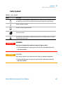
Safety Notices
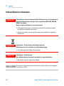
CAUTION
A CAUTION notice denotes a
hazard. It calls attention to an
operating procedure, practice, or
the like that, if not correctly performed or adhered to, could
result in damage to the product
or loss of important data. Do not
proceed beyond a CAUTION
notice until the indicated conditions are fully understood and
met.
Technology Licenses
The hardware and/or software described in
this document are furnished under a license
and may be used or copied only in accordance with the terms of such license.
Restricted Rights Legend
If software is for use in the performance of a
U.S. Government prime contract or subcontract, Software is delivered and licensed as
“Commercial computer software” as
defined in DFAR 252.227-7014 (June 1995),
or as a “commercial item” as defined in FAR
2.101(a) or as “Restricted computer software” as defined in FAR 52.227-19 (June
1987) or any equivalent agency regulation
or contract clause. Use, duplication or disclosure of Software is subject to Agilent
Technologies’ standard commercial license
terms, and non-DOD Departments and
Agencies of the U.S. Government will
WA R N I N G
A WARNING notice denotes a
hazard. It calls attention to an
operating procedure, practice,
or the like that, if not correctly
performed or adhered to, could
result in personal injury or
death. Do not proceed beyond a
WARNING notice until the indicated conditions are fully understood and met.
Agilent 1200 Series Autosampler Service Manual
Contents
Contents
1 Introduction to the Autosampler
7
Introduction to the Autosampler 8
Sampling Sequence 10
Sampling Unit 13
Transport Assembly 16
Early Maintenance Feedback (EMF) 18
Electrical Connections 19
Agilent 1200 Series Interfaces 21
2 Site Requirements and Specifications
23
Site Requirements 24
Physical Specifications 27
Performance Specifications 28
3 Installing the Autosampler
33
Unpacking the Autosampler 34
Optimizing the Stack Configuration 37
Installing the Autosampler 40
Installing the Thermostatted Autosampler
Flow Connections 47
Installing the Sample Tray 49
Transporting the Autosampler 50
4 Using the Autosampler
43
51
Solvent Information 52
Sample Trays 54
Choice of Vials and Caps 56
5 Optimizing Performance
59
Optimization for Lowest Carry-over 60
Fast Injection Cycle and Low Delay Volume
Precise Injection Volume 66
Agilent 1200 Series Autosampler Service Manual
64
3
Contents
Choice of Rotor Seal
68
6 Troubleshooting and Diagnostics
69
Agilent Lab Advisor Software 70
Overview of the Sampler’s Indicators and Test Functions 71
Status Indicators 72
Error Messages 74
Maintenance Functions 89
Standard Autosampler Step Commands 99
Troubleshooting 101
Troubleshooting Guide for the Sample Transport Assembly 103
7 Maintenance
111
Introduction into Maintenance and Repair 112
Overview of Main Repair Procedures 116
Early Maintenance Feedback (EMF) 118
Maintenance Functions 120
Simple Repairs 121
8 Repairs
141
Exchanging Internal Parts
142
9 Parts and Materials for Maintenance
193
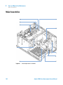
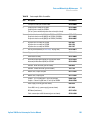
Main Assemblies 194
Analytical-Head Assembly 196
Vial Trays 199
Standard Autosampler Accessory Kit G1329-68725 200
Preparative Autosampler Accessory Kit G2260-68705 201
Maintenance Kit G1313-68730 for G1329A 202
Maintenance Kit G1313-68719 for G1329B 203
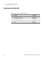
Multi-Draw Kit G1313-6871 204
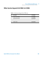
900 µl Injection Upgrade Kit G1363A for G1329A 205
External Tray G1313-60004 206
10 Parts for Repair
207
Sampling Unit Assembly
4
208
Agilent 1200 Series Autosampler Service Manual
Contents
Injection-Valve Assembly 210
Sheet Metal Kit 212
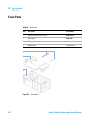
Cover Parts 213
Foam Parts 214
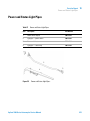
Power and Status Light Pipes 215
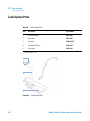
Leak System Parts 216
11 Identifying Cables
217
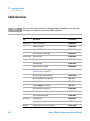
Cable Overview 218
Analog Cables 220
Remote Cables 223
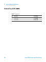
BCD Cables 228
External Contact Cable 230
CAN/LAN Cables 231
Auxiliary Cable 232
RS-232 Cables 233
12 Configuring the Autosampler
235
Autosampler Control and Electronics 236
Position and Movement Sensors 237
Autosampler Main Board (ASM) 238
Firmware Description 243
Optional Interface Boards 246
Agilent 1100/1200 Series Interfaces 250
Setting the 8-bit Configuration Switch 256
Main Power Supply Assembly (Standard) 261
13 Appendix
263
General Safety Information 264
Lithium Batteries Information 268
Radio Interference 269
Sound Emission 270
Agilent Technologies on Internet 271
Agilent 1200 Series Autosampler Service Manual
5
Contents
6
Agilent 1200 Series Autosampler Service Manual
Agilent 1200 Series Autosampler Service Manual
1
Introduction to the Autosampler
Introduction to the Autosampler
8
Sampling Sequence 10
Injection Sequence 11
Sampling Unit 13
Needle-Drive 14
Analytical head / preparative head
Injection-Valve 15
Transport Assembly
14
16
Early Maintenance Feedback (EMF)
Electrical Connections
18
19
Agilent 1200 Series Interfaces
21
Agilent Technologies
7
1
Introduction to the Autosampler
Introduction to the Autosampler
Introduction to the Autosampler
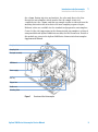
Three models of Agilent 1200 Series autosamplers are available; within this
introduction they will be referred to as the standard autosampler (G1329A),
the standard autosampler SL (G1329B) and the preparative autosampler
(G2260A). Unless otherwise stated all information in this section is valid for
all models.
The Agilent 1100 Series autosamplers and Agilent 1200 Series autosamplers
are designed for use with other modules of the Agilent 1200 Series LC system,
with the HP 1050 Series, or with other LC systems if adequate remote control
inputs and outputs are available. The autosamplerss are controlled from the
Agilent 1200 Series control module (G4208 A Instant Pilot) or from the Agilent
ChemStation for LC.
Three sample-rack sizes are available for the autosamplers. The standard
full-size rack holds 100 × 1.8 ml vials, while the two half-size racks provide
space for 40 × 1.8 ml vials and 15 × 6 ml vials respectively. Any two half-size
rack trays can be installed in the autosamplers simultaneously. A specially
designed sample-rack holding 100 × 1.8 ml vials is available for use with
thermostatted autosamplers. The half-size racks trays are not designed for an
optimal heat transfer when they are used with a thermostatted autosampler.
The autosamplers transport mechanism uses an X-Z-Theta movement to
optimize vial pick-up and return. Vials are picked up by the gripper arm, and
positioned below the sampling unit. The gripper transport mechanism and
sampling unit are driven by motors. Movement is monitored by optical sensors
and optical encoders to ensure correct operation. The metering device is
always flushed after injection to ensure minimum carry-over.
The standard analytical head device provides injection volumes from
0.1 – 100 µl. Two preparative head devices provide injection volumes from
0.1 – 900 µl. One head is limited by a system pressure of 200 bars, the other by
a system pressure of 400 bars. The G1329B autosampler SL uses an analytical
head providing injection volumes from 0.1 – 100 µl for pressures up to 600 bar
as used in rapid resolution systems.
The six-port injection valve unit (only 5 ports are used) is driven by a
high-speed hybrid stepper motor. During the sampling sequence, the valve unit
bypasses the autosamplers, and directly connects the flow from the pump to
8
Agilent 1200 Series Autosampler Service Manual
Introduction to the Autosampler
Introduction to the Autosampler
1
the column. During injection and analysis, the valve unit directs the flow
through the autosamplers which ensures that the sample is injected
completely into the column, and that any sample residue is removed from the
metering unit and needle from before the next sampling sequence begins.
Different valves are available for the standard and preparative autosamplers.
Control of the vial temperature in the thermostatted autosampler is achieved
using an additional Agilent 1200 Series module; the ALS thermostat. Details of
this module are given in the Agilent 1200 Series thermostatted autosampler
Supplemental Manual.
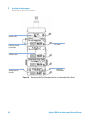
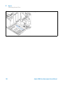
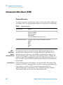
6cVani^XVa]ZVY
HVbea^c\Jc^i
IgVchedgiVhhZbWan
6HBWdVgY
EdlZghjeean
K^VaIgVn
<g^eeZg6gb
CZZYaZhZVi
Hl^iX]^c\KVakZ
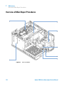
Figure 1
Overview of the Autosampler
Agilent 1200 Series Autosampler Service Manual
9
1
Introduction to the Autosampler
Sampling Sequence
Sampling Sequence
The movements of the autosampler components during the sampling sequence
are monitored continuously by the autosampler processor. The processor
defines specific time windows and mechanical ranges for each movement. If a
specific step of the sampling sequence can’t be completed successfully, an
error message is generated.
Solvent is bypassed from the autosamplers by the injection valve during the
sampling sequence. The sample vial is selected by a gripper arm from a static
sample rack, or from external vial positions. The gripper arm places the
sample vial below the injection needle. The required volume of sample is
drawn into the sample loop by the metering device. Sample is applied to the
column when the injection valve returns to the mainpass position at the end of
the sampling sequence.
The sampling sequence occurs in the following order:
1 The injection valve switches to the bypass position.
2 The plunger of the metering device moves to the initialization position.
3 The gripper arm moves from the home position, and selects the vial. At the
same time, the needle lifts out of the seat.
4 The gripper arm places the vial below the needle.
5 The needle lowers into the vial.
6 The metering device draws the defined sample volume.
7 The needle lifts out of the vial.
8 If the automated needle wash is selected (see “Using the Automated Needle
Wash” on page 61), the gripper arm replaces the sample vial, positions the
wash vial below the needle, lowers the needle into the vial, then lifts the
needle out of the wash vial.
9 The gripper arm checks if the safety flap is in position.
10 The gripper arm replaces the vial, and returns to the home position.
Simultaneously, the needle lowers into the seat.
11 The injection valve switches to the mainpass position.
10
Agilent 1200 Series Autosampler Service Manual
Introduction to the Autosampler
Sampling Sequence
1
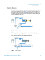
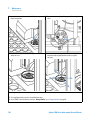
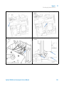
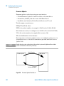
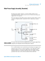
Injection Sequence
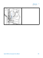
Before the start of the injection sequence, and during an analysis, the injection
valve is in the mainpass position (Figure 2 on page 11). In this position, the
mobile phase flows through the autosamplers metering device, sample loop,
and needle, ensuring all parts in contact with sample are flushed during the
run, thus minimizing carry-over.
Figure 2
Mainpass Position
When the sample sequence begins, the valve unit switches to the bypass
position (Figure 3 on page 11). Solvent from the pump enters the valve unit at
port 1, and flows directly to the column through port 6.
Figure 3
Bypass Position
Agilent 1200 Series Autosampler Service Manual
11
1
Introduction to the Autosampler
Sampling Sequence
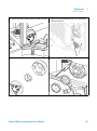
Next, the needle is raised, and the vial is positioned below the needle. The
needle moves down into the vial, and the metering unit draws the sample into
the sample loop (Figure 4 on page 12).
Figure 4
Drawing the Sample
When the metering unit has drawn the required volume of sample into the
sample loop, the needle is raised, and the vial is replaced in the sample tray.
The needle is lowered into the needle seat, and the injection valve switches
back to the mainpass position, flushing the sample onto the column (Figure 5
on page 12).
Figure 5
12
Mainpass Position (Sample Injection)
Agilent 1200 Series Autosampler Service Manual
Introduction to the Autosampler
Sampling Unit
1
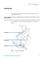
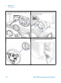
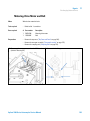
Sampling Unit
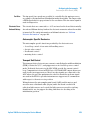
The sampling unit comprises three main assemblies: needle drive, metering
device, and injection valve.
NOTE
The replacement sampling unit excludes the injection valve and metering head assemblies.
The sampling units for the standard and the preparative autosamplers are
different.
CZZYaZYg^kZ
BZiZg^c\YZk^XZ
>c_ZXi^dckVakZ
Figure 6
Autosampler Sampling Unit
Agilent 1200 Series Autosampler Service Manual
13
1
Introduction to the Autosampler
Sampling Unit
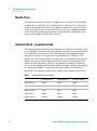
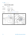
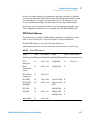
Needle-Drive
The needle movement is driven by a stepper motor connected to the spindle
assembly by a toothed belt. The circular motion of the motor is converted to
linear motion by the drive nut on the spindle assembly. The upper and lower
needle positions are detected by reflection sensors on the sampling unit flex
board, while the needle-in-vial position is determined by counting the motor
steps from the upper needle-sensor position.
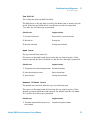
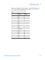
Analytical head / preparative head
The analytical head is driven by the stepper motor connected to the drive shaft
by a toothed belt. The drive nut on the spindle converts the circular movement
of the spindle to linear motion. The drive nut pushes the sapphire plunger
against the tension of the spring into the analytical head. The base of the
plunger sits on the large bearing of the drive nut, which ensures the plunger is
always centered. A ceramic ring guides the movement of the plunger in the
analytical head. The home position of the plunger is sensed by an infra-red
sensor on the sampling unit flex board, while the sample volume is determined
by counting the number of steps from the home position. The backward
movement of the plunger (driven by the spring) draws sample from the vial.
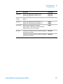
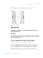
Table 1
14
Analytical Head Technical Data
Standard (100 µl
Standard (900 µl)
Preparative (900 µl)
Number of steps
15000
15000
15000
Volume resolution
7 nl/motor step
60 nl/motor step
60 nl/motor step
Maximum stroke
100 µl
900 µl
900 µl
Pressure limit
600 bar
200 bar
400 bar
Plunger material
Sapphire
Sapphire
Sapphire
Agilent 1200 Series Autosampler Service Manual
Introduction to the Autosampler
Sampling Unit
1
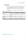
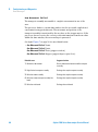
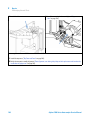
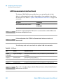
Injection-Valve
The two-position 6-port injection valve is driven by a stepper motor. Only five
of the six ports are used (port 3 is not used). A lever/slider mechanism
transfers the movement of the stepper motor to the injection valve. Two
microswitches monitor switching of the valve (bypass and mainpass end
positions).
No valve adjustments are required after replacing internal components.
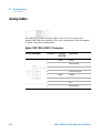
Table 2
Injection-Valve Technical Data
Standard
Preparative MBB™
Autosampler SL
Motor type
4 V, 1.2 A stepper motor
4 V, 1.2 A stepper motor
4 V, 1.2 A stepper motor
Seal material
Vespel™ (Tefzel™
available)
PEEK
PEEK
Stator material
Ceramic/PEEK
PEEK
None
Number of ports
6
6
6
Switching time
< 150 ms
< 150 ms
< 150 ms
Agilent 1200 Series Autosampler Service Manual
15
1
Introduction to the Autosampler
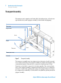
Transport Assembly
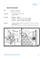
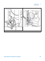
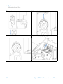
Transport Assembly
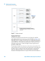
The transport unit comprises an X-axis slide (left-right motion), a Z-axis arm
(up-down motion), and a gripper assembly (rotation and vial-gripping).
Mbdidg
I]ZiVbdidg
<g^eeZgbdidg
MVm^h
<g^eeZg
I]ZiVVm^h
OVm^h
Obdidgcdi^ck^Zl
;aZmWdVgY
Figure 7
Transport Assembly
The transport assembly uses four stepper motors driven in closed-loop mode
for accurate positioning of the gripper assembly for sample-vial transport. The
rotational movement of the motors is converted to linear motion (X- and
Z-axes) by toothed belts connected to the drive spindles. The rotation (theta
axes) of the gripper assembly is transferred from the motor by a toothed belt
and series of gears. The opening and closing of the gripper fingers are driven
by a stepper motor linked by a toothed belt to the planetary gearing inside the
gripper assembly.
16
Agilent 1200 Series Autosampler Service Manual
Introduction to the Autosampler
Transport Assembly
1
The stepper motor positions are determined by the optical encoders mounted
onto the stepper-motor housing. The encoders monitor the position of the
motors continually, and correct for position errors automatically (e.g. if the
gripper is accidentally moved out of position when loading vials into the vial
tray). The initialization positions of the moving components are sensed by
reflection sensors mounted on the flex board. These positions are used by the
processor to calculate the actual motor position. An additional six reflection
sensors for tray recognition are mounted on the flex board at the front of the
assembly.
Agilent 1200 Series Autosampler Service Manual
17
1
Introduction to the Autosampler
Early Maintenance Feedback (EMF)
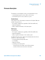
Early Maintenance Feedback (EMF)
The early maintenance feedback (EMF) feature monitors the usage of specific
components in the instrument, and provides feedback when the user-setable
limits have been exceeded. The visual feedback in the user interface provides
an indication that maintenance procedures should be scheduled.
For details on EMF counters and how to use them, see “Early Maintenance
Feedback (EMF)” on page 118.
18
Agilent 1200 Series Autosampler Service Manual
1
Introduction to the Autosampler
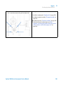
Electrical Connections
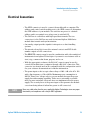
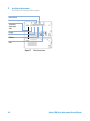
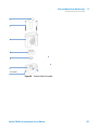
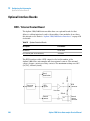
Electrical Connections
• The GPIB connector is used to connect the module with a computer. The
address and control switch module next to the GPIB connector determines
the GPIB address of your module. The switches are preset to a default
address and is recognized once after power is switched ON.
• The CAN bus is a serial bus with high speed data transfer. The two
connectors for the CAN bus are used for internal Agilent 1200 Series
module data transfer and synchronization.
• One analog output provides signals for integrators or data handling
systems.
• The interface board slot is used for external contacts and BCD bottle
number output or LAN connections.
• The REMOTE connector may be used in combination with other analytical
instruments from Agilent Technologies if you want to use features such as
start, stop, common shut down, prepare, and so on.
• With the appropriate software, the RS-232C connector may be used to
control the module from a computer through a RS-232C connection. This
connector is activated and can be configured with the configuration switch.
See your software documentation for further information.
• The power input socket accepts a line voltage of 100 – 240 volts AC ± 10%
with a line frequency of 50 or 60 Hz. Maximum power consumption is
300 VA. There is no voltage selector on your module because the power
supply has wide-ranging capability. There are no externally accessible
fuses, because automatic electronic fuses are implemented in the power
supply. The security lever at the power input socket prevents the module
cover from being taken off when line power is still connected.
NOTE
Never use cables other than the ones supplied by Agilent Technologies to ensure proper
functionality and compliance with safety or EMC regulations.
Agilent 1200 Series Autosampler Service Manual
19
1
Introduction to the Autosampler
Electrical Connections
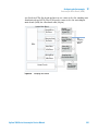
GZaVnXdciVXih
K^VacjbWZgdjieji
GZbdiZ
GH'('8
86C"Wjh
<E>7
8dccZXi^dc
6AH"I]ZgbdhiVi
<&((%7I]ZgbdhiVi
dei^dcVa
Figure 8
20
Autosampler (plus Thermostat) Electrical Connections
Agilent 1200 Series Autosampler Service Manual
1
Introduction to the Autosampler
Agilent 1200 Series Interfaces
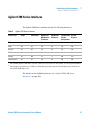
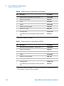
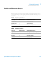
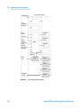
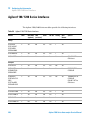
Agilent 1200 Series Interfaces
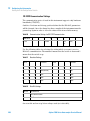
The Agilent 1200 Series modules provide the following interfaces:
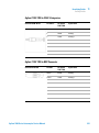
Table 3
Agilent 1200 Series Interfaces
Interface Type
Pumps
Autosampler
DA Detector
MW Detector
FL Detector
VW Detector
RI Detector
Thermostatted Vacuum
Column
Degasser
Compartment
CAN
Yes
Yes
Yes
Yes
Yes
No
GPIB
Yes
Yes
Yes
Yes
Yes
No
RS-232C
Yes
Yes
Yes
Yes
Yes
No
APG Remote
Yes
Yes
Yes
Yes
Yes
Yes
Analog
Yes
No
2×
1×
No
Yes1
Interface board2
Yes
Yes
Yes
Yes
No
No
1
The vacuum degasser will have a special connector for specific use. For details, see the degasser manual.
2
The interface board slot (not common to all modules) provides specific interfacing needs (external contacts, BCD, LAN and so on).
For details on the available interfaces, see “Agilent 1100/1200 Series
Interfaces” on page 250.
Agilent 1200 Series Autosampler Service Manual
21
1
22
Introduction to the Autosampler
Agilent 1200 Series Interfaces
Agilent 1200 Series Autosampler Service Manual
Agilent 1200 Series Autosampler Service Manual
2
Site Requirements and Specifications
Site Requirements 24
Power Consideration
Power Cords 25
Bench Space 26
Environment 26
Physical Specifications
24
27
Performance Specifications
28
Agilent Technologies
23
2
Site Requirements and Specifications
Site Requirements
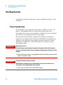
Site Requirements
A suitable environment is important to ensure optimum performance of the
instrument.
Power Consideration
The autosampler power supply has wide-ranging capability (see Table 4 on
page 27). Consequently there is no voltage selector in the rear of the
autosampler. There are also no externally accessible fuses, because automatic
electronic fuses are implemented in the power supply.
The thermostatted autosampler comprises two modules, the standard or
preparative autosampler and the thermostat (G1330B). Both modules have a
separate power supply and a power plug for the line connections. The two
modules are connected by a control cable and both are turned on by the
autosampler module.
WA R N I N G
Damaged electronics
Disconnecting or reconnecting the sampler to thermostat cable when the power
cords are connected to either of the two modules will damage the electronics of the
modules.
➔ Make sure the power cords are unplugged before disconnecting or reconnecting the
sampler to thermostat cable.
WA R N I N G
Incorrect line voltage at the instrument
Shock hazard or damage of your instrumentation can result, if the devices are
connected to a line voltage higher than specified.
➔ Connect your instrument to the specified line voltage.
24
Agilent 1200 Series Autosampler Service Manual
2
Site Requirements and Specifications
Site Requirements
CAUTION
Unaccessable power plug.
In case of emergency it must be possible to disconnect the instrument from the power
line at any time.
➔ Make sure the power connector of the instrument can be easily reached and
unplugged.
➔ Provide sufficient space behind the power socket of the instrument to unplug the
cable.
Power Cords
Different power cords are offered as options with the module. The female end
of all power cords is identical. It plugs into the power-input socket at the rear
of the module. The male end of each power cord is different and designed to
match the wall socket of a particular country or region.
WA R N I N G
The absence of ground connection and the use of an unspecified power cord can
lead to electric shock or short circuit.
Electric Shock
➔ Never operate your instrumentation from a power outlet that has no ground
connection.
➔ Never use a power cord other than the Agilent Technologies power cord designed
for your region.
WA R N I N G
Use of unsupplied cables
Using cables not supplied by Agilent Technologies can lead to damage of the
electronic components or personal injury.
➔ Never use cables other than the ones supplied by Agilent Technologies to ensure
proper functionality and compliance with safety or EMC regulations.
Agilent 1200 Series Autosampler Service Manual
25
2
Site Requirements and Specifications
Site Requirements
Bench Space
The autosampler dimensions and weight (see Table 4 on page 27) allow the
instrument to be placed on almost any laboratory bench. The instrument
requires an additional 2.5 cm (1.0 inch) of space on either side, and
approximately 8 cm (3.1 inches) at the rear for the circulation of air, and room
for electrical connections. Ensure the autosampler is installed in a horizontal
position.
The thermostatted autosampler dimensions and weight allow the instrument
to be placed on almost any laboratory bench. The instrument requires an
additional 25 cm (10 inches) of space on either side for the circulation of air,
and approximately 8 cm (3.1 inches) at the rear for electrical connections.
Ensure the autosampler is installed in a level position.
If a complete Agilent 1200 Series system is to be installed on the bench, make
sure that the bench is designed to carry the weight of all the modules. For a
complete system including the thermostatted autosampler it is recommended
to position the modules in two stacks, see “Optimizing the Stack
Configuration” on page 37. Make sure that in this configuration there is 25 cm
(10 inches) space on either side of the thermostatted autosampler for the
circulation of air.
Environment
Your module will work within specifications at ambient temperatures and
relative humidity as described in Table 4 on page 27.
CAUTION
Condensation within the module
Condensation will damage the system electronics.
➔ Do not store, ship or use your module under conditions where temperature
fluctuations could cause condensation within the module.
➔ If your module was shipped in cold weather, leave it in its box and allow it to warm
slowly to room temperature to avoid condensation.
26
Agilent 1200 Series Autosampler Service Manual
2
Site Requirements and Specifications
Physical Specifications
Physical Specifications
Table 4
WA R N I N G
Physical Specifications
Type
Specification
Comments
Weight
14.2 kg (32 lbs)
Dimensions
(width × depth × height)
200 × 345 × 435 mm (8 × 13.5 × 17
inches)
Line voltage
100 – 240 VAC, ± 10%
Line frequency
50 or 60 Hz, ± 5%
Power consumption
300 VA / 200 W / 683 BTU
Maximum
Ambient operating
temperature
0–55 °C (32–131 °F)
See warning “” on page 27
Ambient non-operating
temperature
-40–70 °C (-4–158 °F)
Humidity
< 95%, at 25–40 °C (77–104 °F)
Operating Altitude
Up to 2000 m (6500 ft)
Non-operating altitude
Up to 4600 m (14950 ft)
For storing the module
Safety standards: IEC, CSA,
UL
Installation Category II, Pollution
Degree 2
For indoor use only. Research
Use Only. Not for use in
Diagnostic Procedures.
Wide-ranging capability
Non-condensing
Hot rear panel
Using the autosampler at high environmental temperatures may cause the rear
panel to become hot.
➔ Do not use the autosampler at environmental temperatures higher than 50 °C
(122 °F)
Agilent 1200 Series Autosampler Service Manual
27
2
Site Requirements and Specifications
Performance Specifications
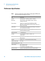
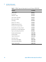
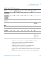
Performance Specifications
Table 5
Performance Specifications Agilent 1200 Series Autosampler (G1329A). Valid
when standard 100 µl metering head installed.
Type
Specification
Pressure
Operating range 0 – 40 MPa (0 – 400 bar, 0 – 5900 psi)
GLP features
Early maintenance feedback (EMF), electronic records of
maintenance and errors
Communications
Controller-area network (CAN). GPIB (IEEE-448), RS232C,
APG-remote standard, optional four external contact closures and
BCD vial number output
Safety features
Leak detection and safe leak handling, low voltages in maintenance
areas, error detection and display
Injection range
0.1 – 100 µl in 0.1 µl increments Up to 1500 µl with multiple draw
(hardware modification required)
Replicate injections
1 – 99 from one vial
Precision
< 0.25% RSD from 5 – 100 µl, < 1% RSD 1 – 5 µl
variable volume
Minimum sample volume
1 µl from 5 µl sample in 100 µl microvial, or 1 µl from 10 µl sample in
300 µl microvial
Carryover
Typically < 0.1%, < 0.05% with external needle cleaning
Sample viscosity range
0.2 – 50 cp
Replicate injections per vial 1 – 99
28
Sample capacity
100 × 2-ml vials in 1 tray
40 × 2-ml vials in ½ tray
15 × 6-ml vials in ½ tray (Agilent vials only)
Injection cycle time
Typically 50 s depending on draw speed and injection volume
Agilent 1200 Series Autosampler Service Manual
Site Requirements and Specifications
Performance Specifications
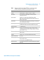
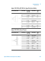
Table 6
2
Performance Specifications Agilent 1200 Series standard autosampler
(G1329A). Valid when standard 900 µl metering head installed.
Type
Specification
Pressure
Operating range 0 – 20 MPa (0 – 200 bar, 0 – 2950 psi)
GLP features
Early maintenance feedback (EMF), electronic records of
maintenance and errors
Communications
Controller-area network (CAN). GPIB (IEEE-448), RS232C,
APG-remote standard, optional four external contact closures and
BCD vial number output
Safety features
Leak detection and safe leak handling, low voltages in maintenance
areas, error detection and display
Injection range
0.1 – 900 µl in 0.1 µl increments (recommended 1 µl increments) Up
to 1800 µl with multiple draw (hardware modification required)
Replicate injections
1 – 99 from one vial
Precision
Typically < 0.5% RSD of peak areas from 5 – 2000 µl, Typically
< 1% RSD of peak areas from 2000 – 5000 µl, Typically < 3% RSD of
peak areas from 1 – 5 µl
Minimum sample volume
1 µl from 5 µl sample in 100 µl microvial, or 1 µl from 10 µl sample in
300 µl microvial
Carryover
Typically < 0.1%, < 0.05% with external needle cleaning
Sample viscosity range
0.2 – 50 cp
Sample capacity
100 × 2-ml vials in 1 tray
40 × 2-ml vials in ½ tray
15 × 6-ml vials in ½ tray (Agilent vials only)
Injection cycle time
50 s for draw speed 200 µl/min, ejection speed 200 µl/min, injection
volume 5 µl
Agilent 1200 Series Autosampler Service Manual
29
2
Site Requirements and Specifications
Performance Specifications
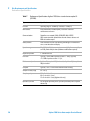
Table 7
30
Performance Specifications Agilent 1200 Series standard autosampler SL
(G1329B).
Type
Specification
Pressure
Operating range 0 – 60 MPa (0 – 600 bar, 0 – 8850 psi)
GLP features
Early maintenance feedback (EMF), electronic records of
maintenance and errors
Communications
Controller-area network (CAN). GPIB (IEEE-448), RS232C,
APG-remote standard, optional four external contact closures and
BCD vial number output
Safety features
Leak detection and safe leak handling, low voltages in maintenance
areas, error detection and display
Injection range
0.1 – 100 µl in 0.1 µl increments (recommended 1 µl increments) Up
to 15 00 µl with multiple draw (hardware modification required)
Replicate injections
1 – 99 from one vial
Precision
Typically < 0.25% RSD of peak areas from 5 – 100 µl, Typically
< 1% RSD of peak areas from 1 – 5 µl,
Minimum sample volume
1 µl from 5 µl sample in 100 µl microvial, or 1 µl from 10 µl sample in
300 µl microvial
Carryover
Typically < 0.1%, < 0.05% with external needle cleaning
Sample viscosity range
0.2 – 50 cp
Sample capacity
100 × 2-ml vials in 1 tray
40 × 2-ml vials in ½ tray
15 × 6-ml vials in ½ tray (Agilent vials only)
Injection cycle time
50 s for draw speed 200 µl/min, ejection speed 200 µl/min, injection
volume 5 µl
Agilent 1200 Series Autosampler Service Manual
Site Requirements and Specifications
Performance Specifications
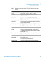
Table 8
2
Performance Specifications Agilent 1200 Series Preparative Autosampler
(G2260A)
Type
Specification
Pressure
Operating range 0 – 40 MPa (0 – 400 bar, 0 – 5800psi)
GLP features
Early maintenance feedback (EMF), electronic records of
maintenance and errors
Communications
Controller-area network (CAN). GPIB (IEEE-448), RS232C,
APG-remote standard, optional four external contact closures and
BCD vial number output
Safety features
Leak detection and safe leak handling, low voltages in maintenance
areas, error detection and display
Injection range
0.1 – 900 µl in 0.1 µl increments (recommended 1 µl increments)
Up to 1800 µl with multiple draw (hardware modification required)
Up to 5000 µl with multiple draw (hardware modification required)
Replicate injections
1 – 99 from one vial
Precision
Typically < 0.5% RSD of peak areas from 5 – 2000 µl, Typically
< 1% RSD of peak areas from 2000 – 5000 µl, Typically < 3% RSD of
peak areas from 1 – 5 µl
Minimum sample volume
1 µl from 5 µl sample in 100 µl microvial, or 1 µl from 10 µl sample in
300 µl microvial
Sample viscosity range
0.2 – 50 cp
Sample capacity
100 × 2-ml vials in 1 tray
15 × 6-ml vials in ½ tray (Agilent vials only)
Injection cycle time
Typically 50 s, depending on draw speed and injection volume
Agilent 1200 Series Autosampler Service Manual
31
2
32
Site Requirements and Specifications
Performance Specifications
Agilent 1200 Series Autosampler Service Manual
Agilent 1200 Series Autosampler Service Manual
3
Installing the Autosampler
Unpacking the Autosampler 34
Damaged Packaging 34
Delivery Checklist 34
Optimizing the Stack Configuration
Installing the Autosampler
37
40
Installing the Thermostatted Autosampler
Flow Connections
43
47
Installing the Sample Tray
49
Transporting the Autosampler
50
Agilent Technologies
33
3
Installing the Autosampler
Unpacking the Autosampler
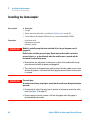
Unpacking the Autosampler
CAUTION
Mechanical damage of the autosampler
If the transport assembly is not parked, the autosampler could be damaged due to
excessive shock of the shipping container during transport.
➔ Always park the transport assembly before shipment (see “Transporting the
Autosampler” on page 50).
Damaged Packaging
Upon receipt of your autosampler, inspect the shipping containers for any
signs of damage. If the containers or cushioning material are damaged, save
them until the contents have been checked for completeness and the
autosampler has been checked mechanically and electrically. If the shipping
container or cushioning material is damaged, notify the carrier and save the
shipping material for the carriers inspection.
Delivery Checklist
Ensure all parts and materials have been delivered with the autosampler. The
instrument box contains the instrument and an Accessory kit. A separate box
contains the reference manual and the power cable.
In Table 9 on page 35 and Table 10 on page 36 are listed the content of each
accessory kit.
Please report missing or damaged parts to your local Agilent Technologies
sales and service office.
34
Agilent 1200 Series Autosampler Service Manual
Installing the Autosampler
Unpacking the Autosampler
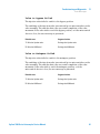
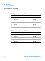
Table 9
G1329A/G1329B - Standard Autosampler Accessory Kit Contents G1329-68725
Description
Part Number
Tubing assembly
5063-6527
CAN cable, 1 m long
5181-1519
Screw cap vials, clear 100/pk
5182-0714
Blue screw caps 100/pk
5182-0717
Label halftray
5989-3890
Vial instruction sheet
no PN
Wrenches 1/4 - 5/16 inch
8710-0510
Rheotool socket wrench 1/4 inch
8710-2391
Hex key 4 mm, 15 cm long, T-handle
8710-2392
Hex key 9/64 inch, 15 cm long, T- handle
8710-2394
Hex key 2.5 mm, 15 cm long, straight handle
8710-2412
Finger caps (x3)1
5063-6506
Front door cooled autosampler
G1329-40301
Air channel adapter
G1329-43200
Cover insulation
no PN
Capillary 0.17 mm, 900 mm
G1329-87300
Capillary heat exchanger
01090-87306
Note for Agilent 1200 Series Autosampler door upgrade
no PN
1
3
Reorder gives pack of 15
Agilent 1200 Series Autosampler Service Manual
35
3
Installing the Autosampler
Unpacking the Autosampler
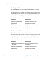
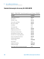
Table 10
36
G2260A - Preparative Autosampler Accessory Kit Contents G2260-68705
Description
Part Number
Tubing assembly
5063-6527
Filter promo kit
5064-8240
CAN cable, 1 m long
5181-1519
Screw cap vials, clear 100/pk
5182-0714
Blue screw caps 100/pk
5182-0717
Label halftray
5989-3890
Wrenches 1/4 - 5/16 inch
8710-0510
Rheotool socket wrench 1/4 inch
8710-2391
Hex key 4 mm, 15 cm long, T-handle
8710-2392
Hex key 9/64 inch, 15 cm long, T- handle
8710-2394
Hex key 2.5 mm, 15 cm long, straight handle
8710-2412
Finger caps x3 (reorder gives pack of 15)
5063-6506
Front door cooled autosampler
G1329-40301
Air channel adapter
G1329-43200
Tray for 15 x 6 ml vials (x2)
G1313-44513
Union, loop extension
5022-2133
Seat extension capillary (500 µl)
G1313-87307
Seat extension capillary (1500 µl)
G1313-87308
Sampler - Column capillary
G2260-87300
Agilent 1200 Series Autosampler Service Manual
Installing the Autosampler
Optimizing the Stack Configuration
3
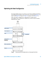
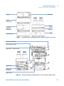
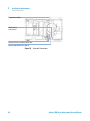
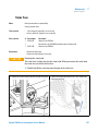
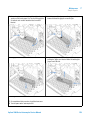
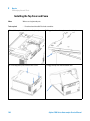
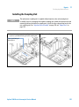
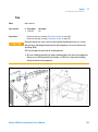
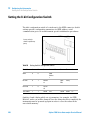
Optimizing the Stack Configuration
If your autosampler is part of a system, you can ensure optimum performance
by installing the autosampler in the stack in the position shown in Figure 9 on
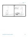
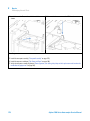
page 37 and Figure 10 on page 38. Figure 11 on page 39 and Figure 12 on
page 39 show the configuration recommended for a thermostatted
autosampler. These configurations optimize the system flow path, ensuring
minimum delay volume.
HdakZciXVW^cZi
KVXjjbYZ\VhhZg
Ejbe
>chiVciE^adi
6jidhVbeaZgdg
EgZeVgVi^kZ
6jidhVbeaZg
8dajbcXdbeVgibZci
9ZiZXidg
Figure 9
Recommended Stack Configuration for an Autosampler (Front View)
Agilent 1200 Series Autosampler Service Manual
37
3
Installing the Autosampler
Optimizing the Stack Configuration
GZbdiZXVWaZ
68edlZg
86C7jhXVWaZid
>chiVciE^adi
86C7jhXVWaZ
A6CidA8
8]ZbHiVi^dc
6cVad\h^\cVaid
gZXdgYZg
Figure 10
38
Recommended Stack Configuration for an Autosampler (Rear View)
Agilent 1200 Series Autosampler Service Manual
Installing the Autosampler
Optimizing the Stack Configuration
3
>chiVciE^adi
9ZiZXidg
8dajbc
8dbeVgibZci
HdakZci
8VW^cZi
HiVcYVgYdg
EgZeVgVi^kZ
6jidhVbeaZg
9Z\VhhZg
Ejbe
6AHI]ZgbdhiVi
Figure 11
Recommended Stack Configuration for a thermostatted ALS (Front View)
A6CidA88]ZbHiVi^dc
6cVad\h^\cVaidgZXdgYZg
6jidhVbeaZg"I]ZgbdhiViXVWaZ
GZbdiZXVWaZ
6cVad\h^\cVa
idgZXdgYZg
86CWjhXVWaZ
Figure 12
Recommended Stack Configuration for a thermostatted ALS (Rear View)
Agilent 1200 Series Autosampler Service Manual
39
3
Installing the Autosampler
Installing the Autosampler
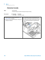
Installing the Autosampler
Parts required
Preparations
WA R N I N G
#
Description
1
Sampler
1
Power cord, for the other cables see below and “Cable Overview” on page 218
1
Control Software (ChemStation, EZChrom, OL, etc.) and/or Control Module G1323B
•
•
•
Locate bench space
Provide power connection
Unpack the Sampler
Module is partially energized when switched off, as long as the power cord is
plugged in.
Risk of stroke and other personal injury. Repair work at the module can lead to
personal injuries, e. g. shock hazard, when the module cover is opened and the
instrument is connected to power.
➔ Never perform any adjustment, maintenance or repair of the module with the top
cover removed and with the power cord plugged in.
➔ The security lever at the power input socket prevents that the module cover is taken
off when line power is still connected. Never plug the power line back in when cover
is removed.
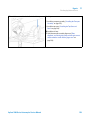
WA R N I N G
Personal injury
To avoid personal injury, keep fingers away from the needle area during autosampler
operation.
➔ Do not bend the safety flap away from its position, or attempt to remove the safety
cover (see Figure 13 on page 41).
➔ Do not attempt to insert or remove a vial from the gripper when the gripper is
positioned below the needle.
40
Agilent 1200 Series Autosampler Service Manual
3
Installing the Autosampler
Installing the Autosampler
CAUTION
“Defective on arrival” problems
If there are signs of damage to the autosampler, please do not attempt to install the
autosampler. Inspection by Agilent is required to evaluate if the instrument is in good
condition or damaged.
➔ Notify your Agilent sales and service office about the damage.
➔ An Agilent service representative will inspect the instrument at your site and
initiate appropriate actions.
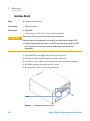
1 Install the LAN interface board in the sampler (if required), see “LAN
Communication Interface Board” on page 248.
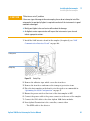
HV[ZinXdkZg
HV[Zin[aVe
Figure 13
Safety Flap
2 Remove the adhesive tape which covers the front door.
3 Remove the front door and remove the transport protection foam.
4 Place the Autosampler on the bench or in the stack as recommended in
“Optimizing the Stack Configuration” on page 37.
5 Ensure the power switch at the front of the Autosampler is OFF.
6 Connect the power cable to the power connector at the rear of the sampler.
7 Connect the CAN cable to the other Agilent 1200 Series modules.
8 If an Agilent Chemstation is the controller, connect either
• The GPIB cable to the detector
Agilent 1200 Series Autosampler Service Manual
41
3
Installing the Autosampler
Installing the Autosampler
• The LAN connector to the LAN interface
9 Connect the APG remote cable (optional) for non Agilent 1200 Series
instruments.
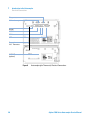
10 Turn ON power by pushing the button at the lower left hand side of the
sampler.
K^VacjbWZgdjieji
86CXVWaZ
idegZk^djhbdYjaZ
GZbdiZ
GH'('8
86C"Wjh
GZaVnXdciVXih
<E>7
Figure 14
42
Cable Connections
NOTE
If the front cover is not installed the autosampler is in a not ready condition and operation is
inhibited.
NOTE
The sampler is turned ON when the line power switch is pressed and the green indicator
lamp is illuminated. The detector is turned OFF when the line power switch is protruding
and the green light is OFF.
Agilent 1200 Series Autosampler Service Manual
Installing the Autosampler
Installing the Thermostatted Autosampler
3
Installing the Thermostatted Autosampler
Parts required
Preparations
WA R N I N G
#
Description
1
Sampler and Thermostat
1
Power cord, for the other cables see below and “Cable Overview” on page 218
1
Control Software (ChemStation, EZChrom, OL, etc.) and/or Control Module G1323B.
•
•
•
Locate bench space
Provide power connection
Unpack the Sampler and the Thermostat
Module is partially energized when switched off, as long as the power cord is
plugged in.
Risk of stroke and other personal injury. Repair work at the module can lead to
personal injuries, e. g. shock hazard, when the module cover is opened and the
instrument is connected to power.
➔ Never perform any adjustment, maintenance or repair of the module with the top
cover removed and with the power cord plugged in.
➔ The security lever at the power input socket prevents that the module cover is taken
off when line power is still connected. Never plug the power line back in when cover
is removed.
WA R N I N G
Damaged electronics
Disconnecting or reconnecting the autosampler to ALS thermostat cable when the
power cords are connected to either of the two modules will damage the electronics
of the modules.
➔ Make sure the power cords are unplugged before disconnecting or reconnecting the
autosampler to ALS thermostat cable.
Agilent 1200 Series Autosampler Service Manual
43
3
Installing the Autosampler
Installing the Thermostatted Autosampler
WA R N I N G
Personal injury
To avoid personal injury, keep fingers away from the needle area during
Autosampler operation.
➔ Do not attempt to insert or remove a vial or a plate when the needle is positioned.
WA R N I N G
Damage through condensation
If the condensation tube is located in liquid the condensed water cannot flow out of
the tube and the outlet is blocked. Any further condensation will then remain in the
instrument. This may damage the instruments electronics.
➔ Make sure that the condensation tube is always above the liquid level in the vessel.
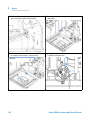
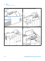
1 Place the Thermostat on the bench.
2 Remove the front cover and route the condensation drain tube to the waste.
8dcYZchVi^dcYgV^cijWZ
LVhiZWdiiaZ
Figure 15
Condensation Leak outlet
3 Install the LAN interface board in the sampler (if required), see “LAN
Communication Interface Board” on page 248
4 Remove the adhesive tape which covers the front door.
5 Remove the front door and remove the transport protection foam.
6 Place the Autosampler on top of the Thermostat. Make sure that the
Autosampler is correctly engaged in the Thermostat locks.
44
Agilent 1200 Series Autosampler Service Manual
Installing the Autosampler
Installing the Thermostatted Autosampler
3
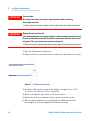
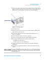
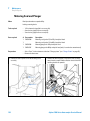
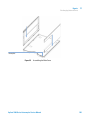
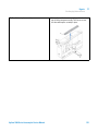
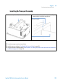
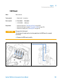
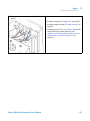
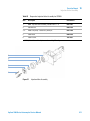
7 Place the air channel adapter into the autosampler tray base. Make sure the
adapter is fully pressed down. This assures that the cold airstream from the
Thermostat is correctly guided to the tray area of the Autosampler.
6^gX]VccZaVYVeiZg
Figure 16
Air channel adapter
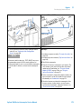
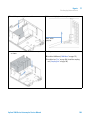
8 Re-install the tray
9 Ensure the power switch on the front of the Autosampler is OFF and the
power cables are disconnected.
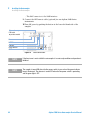
10 Connect the cable between the Autosampler and the Thermostat, see
Figure 17 on page 46.
11 Connect the power cables to the power connectors.
12 Connect the CAN cable to the other Agilent 1200 Series modules.
13 If an Agilent ChemStation is the controller, connect either
• The GPIB cable to the detector
• The LAN connector to the LAN interface
14 Connect the APG remote cable (optional) for non Agilent 1200 Series
instruments.
15 Turn ON power by pushing the button at the lower left hand side of the
sampler.
NOTE
The sampler is turned ON when the line power switch is pressed and the green indicator
lamp is illuminated. The detector is turned OFF when the line power switch is protruding
and the green light is OFF.
Agilent 1200 Series Autosampler Service Manual
45
3
Installing the Autosampler
Installing the Thermostatted Autosampler
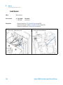
GZaVnXdciVXih
K^VacjbWZgdjieji
I]ZgbdhiVi"
6jidhVbeaZg
XVWaZ
GZbdiZ
GH'('8
86C"Wjh
<E>7
Figure 17
46
Cable Connections
Agilent 1200 Series Autosampler Service Manual
3
Installing the Autosampler
Flow Connections
Flow Connections
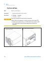
Parts required
Preparations
WA R N I N G
#
Description
1
Parts from the Accessory kit
•
Sampler is installed in the LC system
Toxic and hazardous solvents
The handling of solvents and reagents can hold health risks.
➔ When opening capillary or tube fittings solvents may leak out.
➔ Please observe appropriate safety procedures (for example, goggles, safety gloves
and protective clothing) as described in the material handling and safety data sheet
supplied by the solvent vendor, especially when toxic or hazardous solvents are
used.
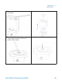
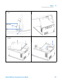
1 Connect the pump outlet capillary to port 1 of the injection valve.
2 Connect column-compartment inlet capillary to port 6 of the injection
valve.
3 Connect the corrugated waste tube to the solvent waste from the leak plane.
4 Ensure that the waste tube is positioned inside the leak channel.
NOTE
Do not extend the waste capillary of the autosampler. The siphoning effect might empty the
complete seat capillary introducing air into the system.
Agilent 1200 Series Autosampler Service Manual
47
3
Installing the Autosampler
Flow Connections
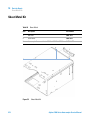
EjbedjiaZiXVe^aaVgn
LVhiZijWZ^c
AZV`X]VccZa
HdakZcilVhiZ[dgXdggj\ViZYlVhiZijWZ
8dajbcXdbeVgibZci^caZiXVe^aaVgn
Figure 18
48
Hydraulic Connections
Agilent 1200 Series Autosampler Service Manual
Installing the Autosampler
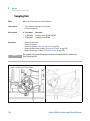
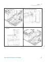
Installing the Sample Tray
3
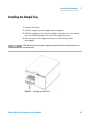
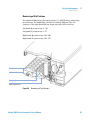
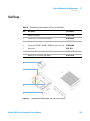
Installing the Sample Tray
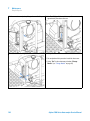
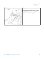
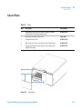
1 Open the front door.
2 Load the sample tray with sample vials as required.
3 Slide the sample tray into the autosampler so that the rear of the sample
tray is seated firmly against the rear of the sample-tray area.
4 Press the front of the sample tray down to secure the tray in the
autosampler.
NOTE
If the thermostatted autosampler tray pops out of position the air channel adapter is not
inserted correctly.
Figure 19
Installing the Sample Tray
Agilent 1200 Series Autosampler Service Manual
49
3
Installing the Autosampler
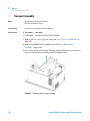
Transporting the Autosampler
Transporting the Autosampler
When moving the autosampler around the laboratory, no special precautions
are needed. However, if the autosampler needs to be shipped to another
location via carrier, ensure:
• The transport assembly is parked (see “Park Arm (Park Gripper)” on
page 94);
• The vial tray is secured.
If the autosampler is to be shipped to another location, the transport assembly
must be moved to the park position to prevent mechanical damage should the
shipping container be subjected to excessive shock. Also, ensure the vial tray
is secured in place with suitable packaging, otherwise the tray may become
loose and damage internal components.
50
Agilent 1200 Series Autosampler Service Manual
Agilent 1200 Series Autosampler Service Manual
4
Using the Autosampler
Solvent Information
Sample Trays
52
54
Choice of Vials and Caps
56
Agilent Technologies
51
4
Using the Autosampler
Solvent Information
Solvent Information
Observe the following recommendations on the use of solvents.
Flow Cell
Avoid the use of alkaline solutions (pH > 9.5) which can attack quartz and thus
impair the optical properties of the flow cell.
Prevent any crystallization of buffer solutions. This will lead into a
blockage/damage of the flow cell.
If the flow cell is transported while temperatures are below 5 °C, it must be
assured that the cell is filled with alcohol.
Aqueous solvents in the flow cell can built up algae. Therefore do not leave
aqueous solvents sitting in the flow cell. Add small % of organic solvents (e.g.
Acetonitrile or Methanol ~5%).
Solvents
Brown glass ware can avoid growth of algae.
Always filter solvents, small particles can permanently block the capillaries.
Avoid the use of the following steel-corrosive solvents:
• Solutions of alkali halides and their respective acids (for example, lithium
iodide, potassium chloride, and so on).
• High concentrations of inorganic acids like nitric acid, sulfuric acid
especially at higher temperatures (replace, if your chromatography method
allows, by phosphoric acid or phosphate buffer which are less corrosive
against stainless steel).
• Halogenated solvents or mixtures which form radicals and/or acids, for
example:
2CHCl3 + O2 –> 2COCl2 + 2HCl
This reaction, in which stainless steel probably acts as a catalyst, occurs
quickly with dried chloroform if the drying process removes the stabilizing
alcohol.
52
Agilent 1200 Series Autosampler Service Manual
4
Using the Autosampler
Solvent Information
• Chromatographic grade ethers, which can contain peroxides (for example,
THF, dioxane, di-isopropylether). Such ethers should be filtered through
dry aluminium oxide which adsorbs the peroxides.
• Solutions of organic acids (acetic acid, formic acid, and so on) in organic
solvents. For example, a 1% solution of acetic acid in methanol will attack
steel.
• Solutions containing strong complexing agents (for example, EDTA,
ethylene diamine tetra-acetic acid).
• Mixtures of carbon tetrachloride with 2-propanol or THF.
Agilent 1200 Series Autosampler Service Manual
53
4
Using the Autosampler
Sample Trays
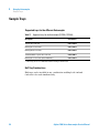
Sample Trays
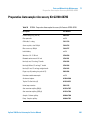
Supported trays for the different Autosampler
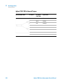
Table 11
Supported trays for the Autosampler (G1329A/ G2260A)
Description
Part Number
Tray for 100 x 2 ml vials
G1313-44510
Halftray for 15 x 6 ml vials
G1313-44513
Halftray for 40 x 2 ml vials
G1313-44512
Thermostattable Tray for 100 x 2 ml vials
G1329-60011
Halftray for 15 x 6 ml vials (for G2260A only1)
G1313-44513
1
This tray is not recommended when using a thermostat
Half-Tray Combinations
Half-trays can be installed in any combination enabling both 2 ml-and
6 ml-vials to be used simultaneously.
54
Agilent 1200 Series Autosampler Service Manual
Using the Autosampler
Sample Trays
4
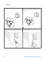
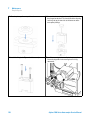
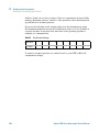
Numbering of Vial Positions
The standard 100-vial tray has vial positions 1 to 100. However, when using
two half-trays, the numbering convention is slightly different. The vial
positions of the right-hand half tray begin at position 101 as follows:
Left-hand 40-position tray: 1 - 40
Left-hand 15-position tray: 1–15
Right-hand 40-position tray: 101–140
Right-hand 15-position tray: 101–115
Edh^i^dc&
AZ[i]VcY]Va[igVn
Edh^i^dc&%&
G^\]i]VcY]Va[igVn
Figure 20
Numbering of Tray Positions
Agilent 1200 Series Autosampler Service Manual
55
4
Using the Autosampler
Choice of Vials and Caps
Choice of Vials and Caps
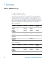
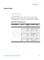
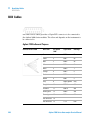
List of Compatible Vials and Caps
For reliable operation vials used with the Agilent 1200 Series autosampler
must not have tapered shoulders or caps that are wider than the body of the
vial. The vials in Table 12 on page 56, Table 13 on page 56 and Table 14 on
page 57 and caps in Table 15 on page 57, Table 16 on page 57 and Table 17 on
page 57 (shown with their Part numbers) have been successfully tested using a
minimum of 15,000 injections with the Agilent 1200 Series autosampler.
Table 12
Description
Volume (ml)
100/Pack
1000/Pack
Clear glass
2
5181-3375
5183-4491
Clear glass,
write-on spot
2
5182-0543
5183-4492
5183-4494
Amber glass,
write-on spot
2
5182-3376
5183-4493
5183-4495
Polypropylene,
wide opening
1
5182-0567
Polypropylene,
wide opening
0.3
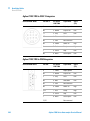
Table 13
56
Crimp Top Vials
100/Pack
(silanized)
5183-4496
9301-0978
Snap Top Vials
Description
Volume (ml)
100/Pack
1000/Pack
100/Pack
(silanized)
Clear glass
2
5182-0544
5183-4504
5183-4507
Clear glass,
write-on spot
2
5182-0546
5183-4505
5183-4508
Amber glass,
write-on spot
2
5182-0545
5183-4506
5183-4509
Agilent 1200 Series Autosampler Service Manual
Using the Autosampler
Choice of Vials and Caps
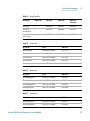
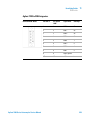
Table 14
Screw Top Vials
Description
Volume (ml)
100/Pack
1000/Pack
100/Pack
(silanized)
Clear glass
2
5182-0714
5183-2067
5183-2070
Clear glass,
write-on spot
2
5182-0715
5183-2068
5183-2071
Amber glass,
write-on spot
2
5182-0716
5183-2069
5183-2072
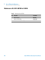
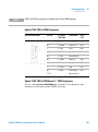
Table 15
Crimp Caps
Description
Septa
100/Pack
Silver aluminum
Clear PTFE/red rubber
5181-1210
Silver aluminum
Clear PTFE/red rubber
5183-4498 (1000/Pack)
Blue aluminum
Clear PTFE/red rubber
5181-1215
Green aluminum
Clear PTFE/red rubber
5181-1216
Red aluminum
Clear PTFE/red rubber
5181-1217
Description
Septa
100/Pack
Clear polypropylene
Clear PTFE/red rubber
5182-0550
Blue polypropylene
Clear PTFE/red rubber
5182-3458
Green polypropylene
Clear PTFE/red rubber
5182-3457
Red polypropylene
Clear PTFE/red rubber
5182-3459
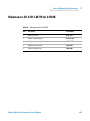
Description
Septa
100/Pack
Blue polypropylene
Clear PTFE/red rubber
5182-0717
Green polypropylene
Clear PTFE/red rubber
5182-0718
Table 16
Table 17
4
Snap Caps
Screw Caps
Agilent 1200 Series Autosampler Service Manual
57
4
Using the Autosampler
Choice of Vials and Caps
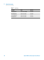
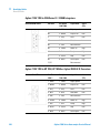
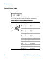
Table 17
58
Screw Caps
Description
Septa
100/Pack
Red polypropylene
Clear PTFE/red rubber
5182-0719
Blue polypropylene
Clear PTFE/silicone
5182-0720
Green polypropylene
Clear PTFE/silicone
5182-0721
Red polypropylene
Clear PTFE/silicone
5182-0722
Agilent 1200 Series Autosampler Service Manual
Agilent 1200 Series Autosampler Service Manual
5
Optimizing Performance
Optimization for Lowest Carry-over 60
Using the Automated Needle Wash 61
Using an Injector Program 62
General Recommendation to Lowest Carry-over
63
Fast Injection Cycle and Low Delay Volume 64
Overlapped Injection Mode 64
General Recommendations for Fast Injection Cycle Times
65
Precise Injection Volume 66
Draw and Eject Speed 66
Choice of Rotor Seal
68
Agilent Technologies
59
5
Optimizing Performance
Optimization for Lowest Carry-over
Optimization for Lowest Carry-over
Several parts of an injection system can contribute to carry-over:
• needle outside
• needle inside
• needle seat
• sample loop
• seat capillary
• injection valve
The autosampler continuous flow-through design ensures that sample loop,
needle inside, seat capillary, and the mainpass of the injection valve is always
in the flow line. These parts are continuously flushed during an isocratic and
also during a gradient analysis. The residual amount of sample remaining on
the outside of the needle after injection may contribute to carry-over in some
instances. When using small injection volumes or when injecting samples of
low concentration immediately after samples of high concentration, carry-over
may become noticeable. Using the automated needle wash enables the
carry-over to be minimized and prevents also contamination of the needle
seat.
60
Agilent 1200 Series Autosampler Service Manual
Optimizing Performance
Optimization for Lowest Carry-over
5
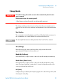
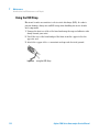
Using the Automated Needle Wash
The automated needle wash can be programmed either as “injection with
needle wash” or the needle wash can be included into the injector program.
When the automated needle wash is used, the needle is moved into a wash vial
after the sample is drawn. By washing the needle after drawing a sample, the
sample is removed from the surface of the needle immediately.
Uncapped Wash Vial
For best results, the wash vial should contain solvent in which the sample
components are soluble, and the vial should not be capped. If the wash vial is
capped, small amounts of sample remain on the surface of the septum, which
may be carried on the needle to the next sample.
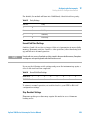
Injector Program with Needle Wash
The injector program includes the command NEEDLE WASH. When this
command is included in the injector program, the needle is lowered once into
the specified wash vial before injection.
For example:
1 DRAW 5 µl
2 NEEDLE WASH vial 7
3 INJECT
Line 1 draws 5 µl from the current sample vial. Line 2 moves the needle to vial
7. Line 3 injects the sample (valve switches to main pass).
Agilent 1200 Series Autosampler Service Manual
61
5
Optimizing Performance
Optimization for Lowest Carry-over
Using an Injector Program
The process is based on a program that switches the bypass grove of the
injection valve into the flow line for cleaning. This switching event is
performed at the end of the equilibration time to ensure that the bypass grove
is filled with the start concentration of the mobile phase. Otherwise the
separation could be influenced, especially if microbore columns are used.
For example:
Outside wash of needle in vial 7 before injection
Injector program:
Draw x.x (y) µl from sample
NEEDLE WASH vial 7
Inject
Wait (equilibration time - see text above)
Valve bypass
Wait 0.2 min
Valve mainpass
Valve bypass
Valve mainpass
NOTE
62
Overlapped injection together with additional injection valve switching is not possible.
Agilent 1200 Series Autosampler Service Manual
Optimizing Performance
Optimization for Lowest Carry-over
5
General Recommendation to Lowest Carry-over
• For samples where needle outside cannot be cleaned sufficiently with water
or alcohol use wash vials with an appropriate solvent. Using an injector
program and several wash vials can be used for cleaning.
In case the needle seat has got contaminated and carry-over is significantly
higher than expected, the following procedure can be used to clean the needle
seat:
• Go to MORE INJECTOR and set needle to home position.
• Pipette an appropriate solvent on to the needle seat. The solvent should be
able to dissolve the contamination. If this is not known use 2 or 3 solvents
of different polarity. Use several milliliters to clean the seat.
• Clean the needle seat with a tissue and remove all liquid from it.
• RESET the injector.
Agilent 1200 Series Autosampler Service Manual
63
5
Optimizing Performance
Fast Injection Cycle and Low Delay Volume
Fast Injection Cycle and Low Delay Volume
Short injection cycle times for high sample througput is one of the most
important requirements in analytical laboratories. In order to shorten cycle
times, you can:
• shorten the column length
• use high flow rates
• apply a steep gradient
Having optimized these parameters, further reduction of cycle times can be
obtained using the overlapped injection mode.
Overlapped Injection Mode
In this process, as soon as the sample has reached the column, the injection
valve is switched back to bypass and the next injection cycle starts but waits
with switching to mainpass until the actual run is finished. You gain the
sample preparation time when using this process.
Switching the valve into the bypass position reduces the system delay volume,
the mobile phase is directed to the column without passing sample loop,
needle and needle seat capillary. This can help to have faster cycle times
especially if low flow rates have to be used like it is mandatory in narrow bore
and micro bore HPLC.
NOTE
Having the valve in bypass position can increase the carry-over in the system.
The injection cycle times also depend on the injection volume. In identically
standard condition, injecting 100 µl instead of 1 µl, increase the injection time
by approximately 8 sec. In this case and if the viscosity of the sample allows it,
the draw and eject speed of the injection system has to be increased.
64
Agilent 1200 Series Autosampler Service Manual
Optimizing Performance
Fast Injection Cycle and Low Delay Volume
NOTE
5
For the last injection of the sequence with overlapped injections it has to be considered
that for this run the injection valve is not switched as for the previous runs and
consequently the injector delay volume is not bypassed. This means the retention times are
prolonged for the last run. Especially at low flow rates this can lead to retention time
changes which are too big for the actual calibration table. To overcome this it is
recommended to add an additional “blank” injection as last injection to the sequence.
General Recommendations for Fast Injection Cycle Times
As described in this section, the first step to provide short cycle times are
optimizing the chromatographic conditions. If this is done the autosampler
parameter should be set to:
• Overlapped injection mode
• Increase of draw and eject speed for large injection volumes
• Add at last run a blank, if overlapped injection is used
To reduce the injection time, the detector balance has to be set to OFF.
Agilent 1200 Series Autosampler Service Manual
65
5
Optimizing Performance
Precise Injection Volume
Precise Injection Volume
Injection Volumes Less Than 2 µl
When the injection valve switches to the BYPASS position, the mobile phase in
the sample loop is depressurized. When the syringe begins drawing sample,
the pressureof the mobile phase is decreased further. If the mobile phase is
not degassed adequately, small gas bubbles may form in the sample loop
during the injection sequence. When using injection volumes < 2 µl, these gas
bubbles may affect the injection-volume precision. For best injection-volume
precision with injection volumes < 2 µl, use of the Agilent 1200 Series degasser
is recommended to ensure the mobile phase is adequately degassed. Also,
using the automated needle wash (see “Optimization for Lowest
Carry-over” on page 60) between injections reduces carry-over to a minimum,
further improving the injection volume precision.
Draw and Eject Speed
Draw Speed
The speed at which the metering unit draws sample out of the vial may have an
influence on the injection volume precision when using viscous samples. If the
draw speed is too high, air bubbles may form in the sample plug, affecting
precision. The default draw speed is 200 µl/min for the autosampler and
1000 µl/min for the preparative autosampler. This speed is suitable for the
majority of applications, however, when using viscous samples, set the draw
speed to lower speed for optimum results. A “DRAW” statement in an injector
program also uses the draw speed setting which is configured for the
autosampler.
Eject Speed
The default eject speed setting is 200 µl/min for the standard autosampler and
1000 µl/min for the preparative autosampler. When using large injection
volumes, setting the eject speed to a higher value speeds up the injection cycle
66
Agilent 1200 Series Autosampler Service Manual
Optimizing Performance
Precise Injection Volume
5
by shortening the time the metering unit requires to eject solvent at the
beginning of the injection cycle (when the plunger returns to the home
position).
An “EJECT” statement in an injector program also uses the eject speed setting
which is configured for the autosampler. A faster eject speed shortens the time
required to run the injector program. When using viscous samples, a high eject
speed should be avoided.
Agilent 1200 Series Autosampler Service Manual
67
5
Optimizing Performance
Choice of Rotor Seal
Choice of Rotor Seal
Vespel™ Seal (for standard valves only)
The standard seal has sealing material made of Vespel. Vespel is suitable for
applications using mobile phases within the pH range of 2.3 to 9.5, which is
suitable for the majority of applications. However, for applications using
mobile phases with pH below 2.3 or above 9.5, the Vespel seal may degrade
faster, leading to reduced seal lifetime.
Tefzel™ Seal (for standard valve only)
For mobile phases with pH below 2.3 or above 9.5, or for conditions where the
lifetime of the Vespel seal is drastically reduced, a seal made of Tefzel is
available (see “Injection-Valve Assembly” on page 210). Tefzel is more resistant
than Vespel to extremes of pH, however, is a slightly softer material. Under
normal conditions, the expected lifetime of the Tefzel seal is shorter than the
Vespel seal, however, Tefzel may have the longer lifetime under more extreme
mobile phase conditions.
PEEK Seal (for preparative injection valve only)
The preparative injection valve has a sealing material made of PEEK. This
material has high chemical resistance and versatility. It is suitable for
application using mobile phases within a pH between 1 and 14.
This seal is also used for the G1329B module.
NOTE
68
Strong oxidizing acids such as concentrated nitric and sulfuric acids are not compatible
with PEEK.
Agilent 1200 Series Autosampler Service Manual
Agilent 1200 Series Autosampler Service Manual
6
Troubleshooting and Diagnostics
Agilent Lab Advisor Software
70
Overview of the Sampler’s Indicators and Test Functions
71
Status Indicators 72
Power Supply Indicator 73
Instrument Status Indicator 73
Error Messages
74
Maintenance Functions 89
User Interface 90
Change Needle 91
Change Piston 93
Park Arm (Park Gripper) 94
Change Gripper (Change Arm)
Tray Alignment 97
96
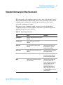
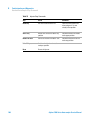
Standard Autosampler Step Commands
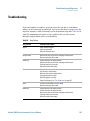
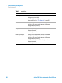
Troubleshooting
99
101
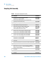
Troubleshooting Guide for the Sample Transport Assembly 103
Intermittent lock-ups with or without vial in the gripper fingers 104
Jittery (shaky) movement in X and or theta axes and/or when the
needle goes through the gripper arm into the vial 106
Poor alignment, seen during vial pickup and vial replacement and/or
when the needle hits the gripper arm 108
Agilent Technologies
69
6
Troubleshooting and Diagnostics
Agilent Lab Advisor Software
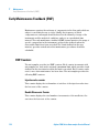
Agilent Lab Advisor Software
The Agilent Lab Advisor Software is a standalone product that can be used
with or without data system. Agilent Lab Advisor helps to manage the lab for
high quality chromatographic results and can monitor in real time a single
Agilent LC or all the Agilent GCs and LCs configured on the lab intranet.
Agilent Lab Advisor provides diagnostic capabilities for all Agilent 1200 Series
HPLC modules. This includes tests and calibrations procedures as well as the
different injector steps to perform all the maintenance routines.
Agilent Lab Advisor also allows users to monitor the status of their LC
instruments. The Early Maintenance Feedback (EMF) feature helps to carry
out preventive maintenance. In addition, users can generate a status report for
each individual LC instrument. The tests and diagnostic features as provided
by the Agilent Lab Advisor Software may differ from the descriptions in this
manual. For details refer to the Agilent Lab Advisor help files.
This manual provides lists with the names of Error Messages, Not Ready
messages, and other common issues.
70
Agilent 1200 Series Autosampler Service Manual
6
Troubleshooting and Diagnostics
Overview of the Sampler’s Indicators and Test Functions
Overview of the Sampler’s Indicators and Test Functions
Status Indicators
The autosamplers are provided with two status indicators which indicate the
operational state (prerun, run, and error states) of the instrument. The status
indicators provide a quick visual check of the operation of the autosampler
(see “Status Indicators” on page 72).
Error Messages
In the event of an electronic, mechanical or hydraulic failure, the instrument
generates an error message in the user interface. For details on error
messages and error handling, please refer to the Agilent Lab Monitor &
Diagnostic Software.
Maintenance Functions
The maintenance functions position the needle arm, gripper assembly, and
metering device for easy access when doing maintenance (see “Maintenance
Functions” on page 120).
Tray Alignment
Tray alignment is required after repair of internal components, or after a
firmware update. The procedure aligns the gripper arm correctly to ensure the
positioning of the gripper arm is correct for all vials (see “Tray Alignment” on
page 97).
Step Commands
The step functions provide the possibility to execute each step of the sampling
sequence individually. The step functions are used primarily for
troubleshooting, and for verification of correct autosampler operation after
repair (see “Standard Autosampler Step Commands” on page 99).
Agilent 1200 Series Autosampler Service Manual
71
6
Troubleshooting and Diagnostics
Status Indicators
Status Indicators
Two status indicators are located on the front of the autosampler. The lower
left indicates the power supply status, the upper right indicates the
autosampler status.
HiVijh^cY^XVidg
EdlZghjeean^cY^XVidg
Figure 21
72
Location of Status Indicators
Agilent 1200 Series Autosampler Service Manual
6
Troubleshooting and Diagnostics
Status Indicators
Power Supply Indicator
The power supply indicator is integrated into the main power switch. When
the indicator is illuminated (green) the power is ON.
Instrument Status Indicator
The instrument status indicator indicates one of four possible instrument
conditions:
• When the status indicator is OFF (and power switch light is on), the
instrument is in a prerun condition, and is ready to begin an analysis.
• A green status indicator, indicates the instrument is performing an analysis
(run mode).
• A yellow indicator indicates a not-ready condition. The instrument is in a
not-ready state when it is waiting for a specific condition to be reached or
completed (for example, front cover not installed), or while a self-test
procedure is running.
• An error condition is indicated when the status indicator is red. An error
condition indicates the instrument has detected an internal problem which
affects correct operation of the instrument. Usually, an error condition
requires attention (for example, leak, defective internal components). An
error condition always interrupts the analysis.
Agilent 1200 Series Autosampler Service Manual
73
6
Troubleshooting and Diagnostics
Error Messages
Error Messages
Error messages are displayed in the user interface when an electronic,
mechanical, or hydraulic (flow path) failure occurs which requires attention
before the analysis can be continued (for example, repair, exchange of
consumables is necessary). In the event of such a failure, the red status
indicator at the front of the module is switched on, and an entry is written to
the instrument log book.
This section describes the meaning of autosampler error messages, and
provides information on probable causes and suggested actions how to recover
from error conditions.
Timeout
The timeout threshold was exceeded.
Probable cause
Suggested actions
1 The analysis was completed successfully,
Check the logbook for the occurrence and
source of a not-ready condition. Restart the
analysis where required.
and the timeout function switched off the
module as requested.
2 A not-ready condition was present during a
sequence or multiple-injection run for a
period longer than the timeout threshold.
74
Check the logbook for the occurrence and
source of a not-ready condition. Restart the
analysis where required.
Agilent 1200 Series Autosampler Service Manual
6
Troubleshooting and Diagnostics
Error Messages
Shut-Down
An external instrument has generated a shut-down signal on the remote line.
The module continually monitors the remote input connectors for status
signals. A LOW signal input on pin 4 of the remote connector generates the
error message.
Probable cause
Suggested actions
1 Leak detected in another module with a CAN Fix the leak in the external instrument before
connection to the system.
restarting the module.
2 Leak detected in an external instrument with Fix the leak in the external instrument before
a remote connection to the system.
3 Shut-down in an external instrument with a
remote connection to the system.
4 The degasser failed to generate sufficient
vacuum for solvent degassing.
restarting the module.
Check external instruments for a shut-down
condition.
Check the vacuum degasser for an error
condition. Refer to the Service Manual for the
Agilent 1200 Series vacuum degasser.
Remote Timeout
A not-ready condition is still present on the remote input.
When an analysis is started, the system expects all not-ready conditions (e.g. a
not-ready condition during detector balance) to switch to run conditions
within one minute of starting the analysis. If a not-ready condition is still
present on the remote line after one minute the error message is generated.
Probable cause
Suggested actions
1 Not-ready condition in one of the
Ensure the instrument showing the not-ready
condition is installed correctly, and is set up
correctly for analysis.
instruments connected to the remote line.
2 Defective remote cable.
Exchange the remote cable.
3 Defective components in the instrument
Check the instrument for defects (refer to the
instrument’s reference documentation).
showing the not-ready condition.
Agilent 1200 Series Autosampler Service Manual
75
6
Troubleshooting and Diagnostics
Error Messages
Synchronization Lost
During an analysis, the internal synchronization or communication between
one or more of the modules in the system has failed.
The system processors continually monitor the system configuration. If one or
more of the modules is no longer recognized as being connected to the system,
the error message is generated.
Probable cause
Suggested actions
1 CAN cable disconnected.
•
Ensure all the CAN cables are connected
correctly.
•
Ensure all CAN cables are installed correctly.
2 Defective CAN cable.
Exchange the CAN cable.
3 Defective main board in a different module.
Switch off the system. Restart the system, and
determine which module or modules are not
recognized by the system.
Leak
A leak was detected in the module.
The signals from the two temperature sensors (leak sensor and
board-mounted temperature-compensation sensor) are used by the leak
algorithm to determine whether a leak is present. When a leak occurs, the leak
sensor is cooled by the solvent. This changes the resistance of the leak sensor
which is sensed by the leak-sensor circuit on the main board.
76
Probable cause
Suggested actions
1 Loose fittings.
Ensure all fittings are tight.
2 Broken capillary.
Exchange defective capillaries.
3 Leaking rotor seal or needle seat.
Exchange the rotor seal or seat capillary.
4 Defective metering seal.
•
Exchange the metering seal.
•
Make sure the leak sensor is thoroughly dry
before restarting the autosampler.
Agilent 1200 Series Autosampler Service Manual
Troubleshooting and Diagnostics
Error Messages
6
Leak Sensor Open
The leak sensor in the module has failed (open circuit).
The current through the leak sensor is dependent on temperature. A leak is
detected when solvent cools the leak sensor, causing the leak-sensor current to
change within defined limits. If the current falls outside the lower limit, the
error message is generated.
Probable cause
Suggested actions
1 Leak sensor not connected to the main
Ensure the leak sensor is connected correctly.
board.
2 Defective leak sensor.
Exchange the leak sensor.
Leak Sensor Short
The leak sensor in the module has failed (short circuit).
The current through the leak sensor is dependent on temperature. A leak is
detected when solvent cools the leak sensor, causing the leak-sensor current to
change within defined limits. If the current increases above the upper limit,
the error message is generated.
Probable cause
Suggested actions
1 Defective leak sensor.
Exchange the leak sensor.
Agilent 1200 Series Autosampler Service Manual
77
6
Troubleshooting and Diagnostics
Error Messages
Compensation Sensor Open
The ambient-compensation sensor (NTC) on the main board in the module has
failed (open circuit).
The resistance across the temperature compensation sensor (NTC) on the
main board is dependent on ambient temperature. The change in resistance is
used by the leak circuit to compensate for ambient temperature changes. If the
resistance across the sensor increases above the upper limit, the error
message is generated.
Probable cause
Suggested actions
1 Defective main board.
Exchange the main board.
Compensation Sensor Short
The ambient-compensation sensor (NTC) on the main board in the module has
failed (short circuit).
The resistance across the temperature compensation sensor (NTC) on the
main board is dependent on ambient temperature. The change in resistance is
used by the leak circuit to compensate for ambient temperature changes. If the
resistance across the sensor falls below the lower limit, the error message is
generated.
78
Probable cause
Suggested actions
1 Defective main board.
Exchange the main board.
Agilent 1200 Series Autosampler Service Manual
6
Troubleshooting and Diagnostics
Error Messages
Fan Failed
The cooling fan in the module has failed.
The hall sensor on the fan shaft is used by the main board to monitor the fan
speed. If the fan speed falls below 2 revolutions/second for longer than
5 seconds, the error message is generated.
Probable cause
Suggested actions
1 Fan cable disconnected.
Ensure the fan is connected correctly.
2 Defective fan.
Exchange fan.
3 Defective main board.
Exchange the main board.
Open Cover
The top foam has been removed.
The sensor on the main board detects when the top foam is in place. If the
foam is removed, the fan is switched off, and the error message is generated.
Probable cause
Suggested actions
1 The top foam was removed during operation. Reinstall the top foam.
2 Foam not activating the sensor.
Replace the top foam.
3 Sensor defective.
Exchange the main board.
Restart Without Cover
The module was restarted with the top cover and foam open.
The sensor on the main board detects when the top foam is in place. If the
module is restarted with the foam removed, the module switches off within
30 s, and the error message is generated.
Probable cause
Suggested actions
1 The module started with the top cover and
Reinstall the top cover and foam.
foam removed.
Agilent 1200 Series Autosampler Service Manual
79
6
Troubleshooting and Diagnostics
Error Messages
Arm Movement Failed
The transport assembly was unable to complete a movement in one of the
axes.
The processor defines a certain time window for the successful completion of
a movement in any particular axis. The movement and position of the
transport assembly is monitored by the encoders on the stepper motors. If the
processor does not receive the correct position information from the encoders
within the time window, the error message is generated.
See figure Figure 7 on page 16 for axes identification.
• Arm Movement 0 Failed: X-axis.
Arm Movement 1 Failed: Z-axis.
Arm Movement 2 Failed: Theta (gripper rotation).
Arm Movement 3 Failed: Gripper (gripper fingers open/close).
Probable cause
Suggested actions
1 Mechanical obstruction.
Ensure unobstructed movement of the transport
assembly.
2 High friction in transport assembly.
Exchange the sample transport assembly.
3 Defective motor assembly.
Exchange the sample transport assembly.
4 Defective sample transport assembly flex
Exchange the sample transport assembly.
board.
5 Defective main board.
80
Exchange the main board.
Agilent 1200 Series Autosampler Service Manual
Troubleshooting and Diagnostics
Error Messages
6
Valve to Bypass Failed
The injection valve failed to switch to the bypass position.
The switching of the injection valve is monitored by two microswitches on the
valve assembly. The switches detect the successful completion of the valve
movement. If the valve fails to reach the bypass position, or if the microswitch
does not close, the error message is generated.
Probable cause
Suggested actions
1 Defective injection valve.
Exchange the injection valve.
2 Defective ASM board.
Exchange the ASM board.
Valve to Mainpass Failed
The injection valve failed to switch to the mainpass position.
The switching of the injection valve is monitored by two microswitches on the
valve assembly. The switches detect the successful completion of the valve
movement. If the valve fails to reach the mainpass position, or if the
microswitch does not close, the error message is generated.
Probable cause
Suggested actions
1 Defective injection valve.
Exchange the injection valve.
2 Defective ASM board.
Exchange the ASM board.
Agilent 1200 Series Autosampler Service Manual
81
6
Troubleshooting and Diagnostics
Error Messages
Needle Up Failed
The needle arm failed to move successfully from the seat or out of the vial to
the upper position.
The upper position of the needle arm is monitored by a position sensor on the
sampling unit flex board. The sensor detects the successful completion of the
needle movement to the upper position. If the needle fails to reach the end
point, or if the sensor fails to recognize the needle arm movement, the error
message is generated.
Probable cause
Suggested actions
1 Defective or dirty position sensor.
Exchange the sampling unit flex board.
2 Defective motor.
Exchange the needle drive motor.
3 Sticking spindle assembly.
Exchange the spindle assembly or sampling unit
assembly.
4 Defective ASM board.
Exchange ASM board.
Needle Down Failed
The needle arm failed to move down into the needle seat.
The lower position of the needle arm is monitored by a position sensor on the
sampling unit flex board. The sensor detects the successful completion of the
needle movement to the needle seat position. If the needle fails to reach the
end point, or if the sensor fails to recognize the needle arm movement, the
error message is generated.
Probable cause
Suggested actions
1 Needle installed incorrectly, or wrong needle Ensure the correct needle type is used, and
type (too long).
82
installed correctly.
2 Defective or dirty position sensor.
Exchange the sampling unit flex board.
3 Defective motor.
Exchange the needle drive motor.
Agilent 1200 Series Autosampler Service Manual
Troubleshooting and Diagnostics
Error Messages
Probable cause
Suggested actions
4 Sticking spindle assembly.
Exchange the spindle assembly or sampling unit
assembly.
5 Defective ASM board.
Exchange the ASM board.
6
Missing Vial
No vial was found in the position defined in the method or sequence.
When the gripper arm picks a vial out of the sample tray, the processor
monitors the gripper motor encoder. If a vial is present, the closing of the
gripper fingers is limited by the vial. However, if no vial is present, the gripper
fingers close too far. This is sensed by the processor (encoder position),
causing the error message to be generated.
Probable cause
Suggested actions
1 No vial in the position defined in the method
Install the sample vial in the correct position, or
edit the method or sequence accordingly.
or sequence.
2 Incorrect gripper alignment.
Align gripper.
3 Defective gripper assembly (defective
Exchange the gripper assembly.
gripper fingers or belt).
4 Defective transport assembly flex board.
Agilent 1200 Series Autosampler Service Manual
Exchange the transport assembly.
83
6
Troubleshooting and Diagnostics
Error Messages
Initialization Failed
The autosampler failed to complete initialization correctly.
The autosampler initialization procedure moves the needle arm and transport
assembly to their home positions in a predefined sequence. During
initialization, the processor monitors the position sensors and motor encoders
to check for correct movement. If one or more of the movements is not
successful, or is not detected, the error message is generated.
Probable cause
Suggested actions
1 Mechanical obstruction.
Ensure unobstructed movement of the transport
assembly.
2 Defective sampling unit flex board.
Exchange the transport assembly.
3 Defective transport assembly flex board.
Exchange the transport assembly.
4 Defective sampling unit motor.
Exchange the defective sampling unit motor.
5 Defective ASM board.
Exchange the ASM board.
Metering Home Failed
The metering plunger has failed to move back to the home position.
The home position sensor on the sampling unit flex board monitors the home
position of the plunger. If the plunger fails to move to the home position, or if
the sensor fails to recognize the plunger position, the error message is
generated.
84
Probable cause
Suggested actions
1 Dirty or defective sensor.
Exchange the sampling unit flex board.
2 Broken plunger.
Exchange the metering plunger and seal.
3 Defective metering-drive motor.
Exchange the metering-drive motor.
4 Defective ASM board.
Exchange the ASM board.
Agilent 1200 Series Autosampler Service Manual
Troubleshooting and Diagnostics
Error Messages
6
Motor Temperature
One of the motors of the transport assembly has drawn excessive current,
causing the motor to become too hot. The processor has switched OFF the
motor to prevent damage to the motor.
See figure Figure 7 on page 16 for motor identification.
• Motor 0 temperature: X-axis motor.
Motor 1 temperature: Z-axis motor.
Motor 2 temperature: Theta (gripper rotation) motor.
Motor 3 temperature: Gripper motor (motor for gripper fingers).
The processor monitors the current drawn by each motor and the time the
motor is drawing current. The current drawn by the motors is dependent on
the load on each motor (friction, mass of components etc.). If the current
drawn is too high, or the time the motor draws current is too long, the error
message is generated.
Probable cause
Suggested actions
1 Mechanical obstruction.
Ensure unobstructed movement of the transport
assembly.
2 High friction in the transport assembly.
Exchange the transport assembly.
3 Motor belt tension too high.
Switch OFF the autosampler at the power
switch. Wait at least 10 minutes before
switching on again.
4 Defective motor.
Exchange the transport assembly.
5 Defective transport assembly flex board.
Exchange the transport assembly.
Agilent 1200 Series Autosampler Service Manual
85
6
Troubleshooting and Diagnostics
Error Messages
Initialization with Vial
The autosampler attempted to initialize with a vial still in the gripper.
During initialization, the autosampler checks correct operation of the gripper
by closing and opening the gripper fingers while monitoring the motor
encoder. If a vial is still in the gripper when initialization is started, the
gripper fingers cannot close causing the error message to be generated.
Probable cause
Suggested actions
1 Vial still in gripper.
Remove the vial using the “Release Vial”
function in the user interface. Reinitialize the
autosampler.
Safety Flap Missing
The safety flap was not detected.
Before the needle moves down into the needle seat to inject sample, the safety
flap locks into position. Next, and the gripper checks the safety flap by trying
to move the safety flap away from the needle. If the gripper is able to move
beyond the safety flap position (safety flap not in position), the error message
is generated.
86
Probable cause
Suggested actions
1 Safety flap missing or broken.
Exchange the safety flap.
Agilent 1200 Series Autosampler Service Manual
Troubleshooting and Diagnostics
Error Messages
6
Vial in Gripper
The gripper arm attempted to move with a vial still in the gripper.
During specific stages of the sampling sequence, no vial should be held by the
gripper. The autosampler checks if a sample vial is stuck in the gripper by
closing and opening the gripper fingers while monitoring the motor encoder. If
the gripper fingers are unable to close, the error message is generated.
Probable cause
Suggested actions
1 Vial still in gripper.
Remove the vial using the “Release Vial”
function in the user interface. Reinitialize the
autosampler.
Missing Wash Vial
The wash vial programmed in the method was not found.
When the gripper arm picks a vial out of the sample tray, the processor
monitors the gripper motor encoder. If a vial is present, the closing of the
gripper fingers is limited by the vial. However, if no vial is present, the gripper
fingers close too far. This is sensed by the processor (encoder position),
causing the error message to be generated.
Probable cause
Suggested actions
1 No wash vial in the position defined in the
Install the wash vial in the correct position, or
edit the method accordingly.
method.
Agilent 1200 Series Autosampler Service Manual
87
6
Troubleshooting and Diagnostics
Error Messages
Invalid Vial Position
The vial position defined in the method or sequence does not exist.
The reflection sensors on the transport assembly flex board are used to check
automatically which sample trays are installed (coding on tray). If the vial
position does not exist in the current sample tray configuration, the error
message is generated.
Probable cause
Suggested actions
1 Incorrect tray or trays installed.
Install the correct trays, or edit the method or
sequence accordingly.
2 Incorrect vial positions defined in the
Exchange the transport assembly.
method or sequence.
3 Tray recognition defective (dirty sample tray
or defective transport assembly flex board).
88
Ensure the coding surfaces of the sample tray
are clean (located at the rear of the sample tray).
Agilent 1200 Series Autosampler Service Manual
Troubleshooting and Diagnostics
Maintenance Functions
6
Maintenance Functions
Certain maintenance procedures require the needle arm, metering device, and
gripper assembly to be moved to specific positions to enable easy access to
components. The maintenance functions move these assemblies into the
appropriate maintenance position. In the ChemStation the ALS maintenance
positions can be selected from the Maintenance menu in the Diagnosis display.
In the Control Module the functions can be selected in the Test screens of the
autosampler.
Agilent 1200 Series Autosampler Service Manual
89
6
Troubleshooting and Diagnostics
Maintenance Functions
User Interface
The functions for the ChemStation and Control Module (different names for
functions in the Control Module are shown in brackets) are:
Change Needle:
moves the safety flap away from the needle, and positions the needle arm for
easy access to the needle and needle seat.
Change Piston:
relieves the tension on the metering spring (draws the piston to the outer
position), enabling easy disassembly of the metering head assembly).
Park Arm (Park Gripper):
secures the gripper arm to the park position behind the sampling unit. ready
for transport or shipping of the autosampler.
Home:
moves the tray arm to its home position for better access and exchange of the
trays.
Change Gripper:
The change gripper function moves the gripper to the front of the autosampler
enabling easy access to the gripper release mechanism.
90
Agilent 1200 Series Autosampler Service Manual
6
Troubleshooting and Diagnostics
Maintenance Functions
Change Needle
WA R N I N G
For needle exchange, the needle arm moves down automatically when the front
cover is removed.
Risk of personal injury due to moving needle.
➔ Keep fingers away from the needle area during needle movement.
The change-needle/seat function moves the safety flap out of position, and
positions the needle for easy exchange and alignment of the needle and needle
seat.
User Interface
The commands for the ChemStation and Control Module (different names for
the commands in the Control Module are shown in brackets) are:
NOTE
The autosampler front cover must be in place when “Start” and “End” are selected.
Start (Change)
Moves the safety flap away from the needle, and positions the needle
approximately 15 mm above the needle seat.
Needle Up (Up Arrow)
Press function key couple of times to move the needle arm up in 2 mm steps.
Needle Down (Down Arrow)
Press function key couple of times to move the needle arm down in 2 mm
steps. The lowest position (“end position”) is used to align the needle at the
correct position in the needle seat.
End (Done)
Completes the procedure by moving the gripper arm to the home position, and
releasing the safety flap.
Agilent 1200 Series Autosampler Service Manual
91
6
Troubleshooting and Diagnostics
Maintenance Functions
Using the Change Needle Function
1 Ensure the front cover is installed.
2 Select “Start” (“Change”) to move the needle arm to the maintenance
position.
3 Remove the front cover.
NOTE
Do not remove the front cover until the needle arm is in its maintenance position. Removing
the cover while the needle arm is activated may lock up the system.
4 Exchange the needle or needle seat (see “Needle-Seat Assembly” on
page 125 and “Needle Assembly” on page 122).
5 Replace the front cover.
6 Select “End” (“Done”) to complete the procedure.
92
Agilent 1200 Series Autosampler Service Manual
Troubleshooting and Diagnostics
Maintenance Functions
6
Change Piston
The change-piston function draws the piston away from the home position,
relieving the tension on the spring. In this position, the analytical head
assembly can be removed and reinstalled easily after maintenance.
User Interface
The commands for the ChemStation and Control Module (different names for
commands in the Control Module are shown in brackets) are:
Start (Change)
Draws the piston away from the home position, relieving the tension on the
spring.
End (Done)
Repositions the plunger at the home position.
Using the Change Seal Function
1 Select “Start” (“Change") to move the piston to the maintenance position.
2 Exchange the metering seal (see “Gripper Arm” on page 138).
3 Select “End” (“Done”) to move the piston back to the home position.
Agilent 1200 Series Autosampler Service Manual
93
6
Troubleshooting and Diagnostics
Maintenance Functions
Park Arm (Park Gripper)
User Interface
In the ChemStation the Park Arm command is part of the ALS maintenance
positions that can be selected from the Maintenance menu in the Diagnosis
display. In the Control Module the Park Gripper command is located in the
Control display of the autosampler.
The commands for the ChemStation and Control Module (different names for
commands in the Control Module are shown in brackets) are:
Park Arm (Park Gripper)
moves the gripper arm to the park position.
Home
moves the gripper arm out of the park position to the home position.
To prepare autosampler for transportation
The park arm function moves the gripper and transport slider to the home
position behind the sampling unit, and lowers the gripper arm into the park
position where the transport assembly is secured against a mechanical stop.
The autosampler can be switched OFF after parking the arm.
When
Before transporting or shipping the autosampler.
CAUTION
Unsecured Transportation of Autosampler
Unsecured transportation of the autosampler may result in mechanical damage to the
gripper and transport slider.
➔ Always secure the arm in the park position.
NOTE
94
Before parking the gripper arm, ensure there is no vial in the gripper. Use the “Release
Gripper” function to remove the vial.
Agilent 1200 Series Autosampler Service Manual
Troubleshooting and Diagnostics
Maintenance Functions
6
1 Select “Park Arm” (“Park Gripper”).
2 When the arm is in the park position, the autosampler is ready for
shipment, and can be switched OFF.
Agilent 1200 Series Autosampler Service Manual
95
6
Troubleshooting and Diagnostics
Maintenance Functions
Change Gripper (Change Arm)
The change gripper function moves the gripper to the front of the autosampler
enabling easy access to the gripper release mechanism.
User Interface
The commands for the ChemStation and Control Module (different names for
commands in the Control Module are shown in brackets) are:
Start (Change)
Moves the transport assembly and gripper arm to the position required to
change the gripper arm.
End (Done)
Repositions the transport assembly and gripper arm to the home position.
Using the Change Seal Function
1 Select “Start” (“Change") to move the gripper arm to the maintenance
position.
2 Exchange the gripper arm (see “Gripper Arm” on page 138).
3 Select “End” (“Done”) to move the gripper arm to the home position.
96
Agilent 1200 Series Autosampler Service Manual
6
Troubleshooting and Diagnostics
Maintenance Functions
Tray Alignment
Tray alignment is required to compensate for small deviations in positioning
of the gripper which may occur after disassembling the module for repair.
The tray alignment procedure uses several tray positions as reference points.
Because the tray is a rectangle, a two-point alignment is sufficient to corrects
all other vial positions within the tray. On completion of the procedure, the
corrected gripper positions are stored in the instrument firmware.
This procedure is supported as indicated in the table below. For Instant Pilot
and Agilent Lab Monitor and Diagnostic Software (LMD) see the online help
for detailed instructions.
Table 18
Supported Controllers and Software Products
Handheld
Controller
G1323B
Instant Pilot
LMD
Firmware B.02.02
or higher
Firmware Rev.
B.02.02
LMD A.02.01 or
higher
For the Handheld Controller please follow the instructions below.
CAUTION
If this procedure is not caried out properly, the autosampler will no longer work unless
switched back to operation by an enforced cold start.
Risk of data loss due to enforced cold start
➔ Carefully follow the instructions below.
NOTE
The screen with the alignment dialog box can be found under the menus Views > System
> Tests > Autosampler.The alignment procedure must be done with the standard
100-position vial tray installed.
In the Control Module the “Align Tray” function is located in the Control display
of the autosampler. Carry out the following steps:
1 Set alignment to factory default:
• Go to Align > Tray and press Default.
Agilent 1200 Series Autosampler Service Manual
97
6
Troubleshooting and Diagnostics
Maintenance Functions
• Go to Align > Transport and press Default.
• Wait while the Autosampler performs a reset and go back to Align >
Transport.
2 Put capped vials into positions #15 and #95 of the 100-vial tray.
3 Move the gripper arm to position of vial #15. Use Enter to hit Goto Vial.
4 Use Arm down(F2) to move the fingers as close as possible to the top of the
vial, without the gripper fingers touching the vial.
5 Use the Up and Down arrows for Theta correction (rotational movement).
6 Use the Left and Right arrows for X-position correction (horizontal
movement).
7 Open the gripper (F4) and move it further down for about 5 mm in such a
way that vial cap and rubber of gripper fingers have the same height.
8 Visually re evaluate if the vial is in the center of the gripper fingers and
correct X- and Theta position accordingly.
9 Press Enter to hit Next Vial; enter
vial #95
and press Goto Vial.
10 Repeat steps 4 to 8 to align the gripper at position #95.
11 Press Average (F8) to balance the alignment.
12 Press Done (F6) to store the alignment permanently in non-volatile memory
and to reset the module.
13 To check the result go back to the alignment dialog box, move to vial
position #15 and #95 to see if the alignment is acceptable.
98
NOTE
To leave the alignment screen without changes use the Esc key.
NOTE
The result can be a compromise e.g. if the X position at #15 and #95 are off to the same
side, then it is OK. However, if at both positions the correction still should be in one
direction or, if the failure in one position is larger than the other, you must restart the
alignment procedure with step 3. The same goes for the Theta correction.
Agilent 1200 Series Autosampler Service Manual
Troubleshooting and Diagnostics
Standard Autosampler Step Commands
6
Standard Autosampler Step Commands
Each movement of the sampling sequence can be done under manual control.
This is useful during troubleshooting, where close observation of each of the
sampling steps is required to confirm a specific failure mode or verify
successful completion of a repair.
Each injector step command actually consists of a series of individual
commands that move the autosampler components to predefined positions,
enabling the specific step to be done.
Table 19
Injector Step Commands
Step
Action
Valve Bypass
Switches injection valve to the bypass
position.
Plunger Home
Moves the plunger to the home
position.
Needle Up
Lifts the needle arm to the upper
position.
Command also switches the
valve to bypass if it is not
already in that position.
Vial to Seat
Moves the selected vial to the seat
position.
Command also lifts the needle
to the upper position.
Needle into Sample
Lowers the needle into the sample.
Command also positions the
vial at the seat, and lifts the
needle to the upper position.
Draw
Metering device draws the defined
injection volume.
Command also positions the
vial at the seat, lifts the
needle, and lowers the needle
into vial. Command can be
done more than once
(maximum draw volume of
100µl cannot be exceeded).
Use Plunger Home to reset the
metering device.
Agilent 1200 Series Autosampler Service Manual
Comments
99
6
Troubleshooting and Diagnostics
Standard Autosampler Step Commands
Table 19
100
Injector Step Commands
Step
Action
Comments
Needle Up
Lifts the needle out of the vial.
Command also switches the
valve to bypass if it is not
already in that position.
Vial to Tray
Returns the selected vial to the tray
position.
Command also lifts the needle
to the upper position.
Needle into Seat
Lowers the needle arm into the seat.
Command also returns the vial
to the tray position.
Valve Mainpass
Switches the injection valve to the
mainpass position.
Reset
Resets the injector.
Agilent 1200 Series Autosampler Service Manual
Troubleshooting and Diagnostics
Troubleshooting
6
Troubleshooting
If the autosampler is unable to perform a specific step due to a hardware
failure, an error message is generated. You can use the injector steps to do the
injection sequence, while observing how the instrument responds. Table 20 on
page 101 summarizes the injector steps, and lists the associated error
messages and probable causes of step failures.
Table 20
Step Failures
Step Function
Probable Failure Modes
Bypass
Valve already in bypass.
Valve not connected.
Defective injection valve.
Plunger Home
Defective or dirty sensor on the sampling-unit flex board.
Defective metering-drive motor.
Needle Up
Needle already in the upper position.
Defective or dirty sensor on the sampling-unit flex board.
Sticking needle-arm assembly.
Defective needle-drive motor.
Vial to Seat
No vial in selected position.
Vial already in seat position.
Defective transport assembly motors.
Sticking transport assembly.
Defective gripper assembly.
Gripper not aligned (see “Tray Alignment” on page 97).
Draw
Sum of all draw volumes exceeds 100µl.
Defective metering-drive motor.
Needle Up
Needle already in the upper position.
Needle already in the upper position.
Defective or dirty sensor on the sampling-unit flex board.
Sticking needle-arm assembly.
Defective needle-drive motor.
Agilent 1200 Series Autosampler Service Manual
101
6
Troubleshooting and Diagnostics
Troubleshooting
Table 20
102
Step Failures
Step Function
Probable Failure Modes
Vial to Tray
Defective transport assembly motors.
Sticking transport assembly.
Defective gripper assembly.
Gripper not aligned (see “Tray Alignment” on page 97).
Needle Down
Needle already in the lower position.
Defective or dirty sensor on the sampling-unit flex board.
Sticking needle-arm assembly.
Defective needle-drive motor.
Mainpass
Valve already in mainpass.
Valve not connected.
Defective injection valve.
Needle Up/Mainpass
Blockage in the sample loop or needle (no solvent flow).
Needle already in the upper position.
Defective or dirty sensor on the sampling-unit flex board.
Sticking needle-arm assembly.
Defective needle-drive motor.Valve already in mainpass.
Valve not connected.
Defective injection valve.
Agilent 1200 Series Autosampler Service Manual
6
Troubleshooting and Diagnostics
Troubleshooting Guide for the Sample Transport Assembly
Troubleshooting Guide for the Sample Transport Assembly
This troubleshooting guide is meant to help you diagnose and repair
autosampler problems.
In general, autosampler problems can be divided into three categories.
1 Intermittent lock-ups with or without vial in the gripper fingers with error
messages
Many times the sampler is being used very heavily.
• motor overtemp (0 or 1 or 2 or 3)
• movement failed (0 or 1 or 2 or 3)
• missing vial
2 Jittery (shaky) movement in X and/or theta axes and/or when the needle
goes through the gripper arm into the vial with error messages
• motor overtemp (0 or 2)
• movement failed (0 or 2)
3 Poor alignment, seen during vial pickup and vial replacement and/or when
the needle hits the gripper arm with error messages
• motor overtemp (0 or 2 or 3)
• movement failed (0 or 2 or 3)
• missing vial
NOTE
Motor 0=X; 1=Z; 2=Theta; 3=Gripper.
Agilent 1200 Series Autosampler Service Manual
103
6
Troubleshooting and Diagnostics
Troubleshooting Guide for the Sample Transport Assembly
Intermittent lock-ups with or without vial in the gripper fingers
With error messages
• motor overtemp (0 or 1 or 2 or 3)
• movement failed (0 or 1 or 2 or 3)
• missing vial
NOTE
When a motor over temperature message has occurred, the sampler must be turned OFF for
about 10 minutes to allow the motor to cool down.
1 Check the firmware and update to the latest revision if necessary.
Since firmware revision A.03.61 (resident A03.60) most “movement failed”,
“motor over temp”, “initialization failed (X-axis)” errors are solved.
2 Check the vials and the caps.
For reliable operation, vials used with the Agilent 1200 Series Autosampler
must not have tapered shoulders or caps that are wider than the body of the
vial. For more details see the service note G1313-017.
3 Very heavy usage - use a macro.
A pre-sequence macro, QMBUVHW_PDF will automatically reset the sampler
at the start of a sequence (ChemStation).
4 Check if the “INJECT” line is used in the “Injector Program”.
Remove this line from the program. In this mode the system does not need
this command to do the injection. A firmware revision (>3.81) will address
this problem. For more details see the service note G1313-018.
5 Reset the sampler alignment to default value.
Reset tray alignment, and transport alignment is possible with the Control
Module and the ChemStation. To reset the transport alignment with the
ChemStation, enter following command in the command line. Print
sendmodule$(lals, “tray:alig 0.00,0.00”)
6 Check the tension of the belts.
For this use the Torque2.mac and measure the torque for each axis.
104
Agilent 1200 Series Autosampler Service Manual
6
Troubleshooting and Diagnostics
Troubleshooting Guide for the Sample Transport Assembly
Table 21
Typical ranges
Theta (both) 30-50
X-axis (both) 50-90
Z-axis (both) 90-130
Gripper open 30-65
Gripper closed maximum 30
NOTE
If the Gripper open/closed torque is not in the range, proceed with STEP 7. If the theta or X
torque is not in the range, proceed with STEP 8 (if you think you can adjust the torque),
otherwise proceed with STEP 9.
7 Exchange the gripper arm assembly (part number G1313-60010).
8 Adjust the belt tension.
• If the measured torque value is too low, the belt needs to be tightened.
• If the measured torque value is too high, the belt needs to be loosened.
For this, slide the motor (X or theta) on the holder bracket in the
appropriate direction and test the tension with the torque2 macro. Repeat
this steps until the values are in the appropriate torque range.
9 Exchange the sample transport assembly (G1329-60009).
10 Exchange the main board (part number G1329-69520).
Agilent 1200 Series Autosampler Service Manual
105
6
Troubleshooting and Diagnostics
Troubleshooting Guide for the Sample Transport Assembly
Jittery (shaky) movement in X and or theta axes and/or when the
needle goes through the gripper arm into the vial
With Error messages
• motor overtemp (0 or 2)
• movement failed (0 or 2)
NOTE
When a motor over temperature message has occurred, the sampler must be turned OFF for
about 10 minutes to allow the motor to cool down.
1 Check the firmware and update to the latest revision if necessary.
Since firmware revision A.03.61 (resident A03.60) most of following errors
“movement failed”, “motor over temp” and “initialization failed (X-axis)” are
solved.
2 Check the cleanliness of the transport rods (X-axis) and clean them.
NOTE
DO NOT lubricate the transport rod.
3 Lubricate the X-gear.
Friction can result in the belt slipping on the gear so that the position of the
belt teeth towards the gear changes.
To avoid this, apply some grease from the sample transport repair kit to the
X-motor-gear.
NOTE
106
Do not use other grease as the one in the kit and carefully follow the instruction from the
technical note.
Agilent 1200 Series Autosampler Service Manual
6
Troubleshooting and Diagnostics
Troubleshooting Guide for the Sample Transport Assembly
4 Check the tension of the belts.
For this use the Macro2.mac and measure the torque for theta and X-axis.
Table 22
Typical ranges
Theta (both) 30-50
X-axis (both) 50-90
• If the theta or X torque is not in the range, proceed with STEP 5 (if you
think you can adjust the torque). Otherwise proceed with STEP 7.
5 Adjust the belts tension.
• If the measured torque value is too low, the belt needs to be tightened.
• If the measured torque value is too high, the belt needs to be loosened.
For this, slide the motor (X or theta) on the holder bracket in the
appropriate direction and test the tension with the Torque2.mac macro.
Repeat this steps until the values are in the appropriate torque range.
6 Reset the sampler alignments to default value.
Reset tray alignment, and transport alignment is possible with the Control
Module and the Chemstation. To reset the transport alignment with the
Chemstation enter following command in the command line:
Print sendmodule$(lals, “tray:alig 0.00,0.00”)
7 Exchange the sample transport assembly (part number G1329-60009).
8 Exchange the main board (part number G1329-69520).
Agilent 1200 Series Autosampler Service Manual
107
6
Troubleshooting and Diagnostics
Troubleshooting Guide for the Sample Transport Assembly
Poor alignment, seen during vial pickup and vial replacement
and/or when the needle hits the gripper arm
With Error messages
• motor overtemp (0 or 2 or 3)
• movement failed (0 or 2 or 3)
NOTE
When a motor over temperature message has occurred, the sampler must be turned OFF for
about 10 minutes to allow the motor to cool down.
1 Check the firmware and update to the latest revision if necessary.
Since revision A.03.61 (resident A03.60) most of following “movement failed”,
“motor over temp” and “initialization failed (X-axis)” errors are solved.
2 Reset the sampler alignment to default value.
Reset tray alignment, and transport alignment is possible with the Control
Module and the Chemstation. To reset the transport alignment with the
Chemstation enter following command in the command line:
Print sendmodule$(lals, “tray:alig 0.00,0.00”)
3 Lubricate the X-gear.
Friction can result in the belt slipping on the gear so that the position of the
belt teeth towards the gear changes. To avoid this, apply some grease from
the sample transport repair kit to the X-motor-gear.
NOTE
108
Do not use other grease as the one in the kit and carefully follow the instruction from the
technical note.
Agilent 1200 Series Autosampler Service Manual
6
Troubleshooting and Diagnostics
Troubleshooting Guide for the Sample Transport Assembly
4 Check the tension of the belts.
For this use the Torque2.mac and measure the torque for each axis.
Table 23
Typical ranges
Theta (both) 30-50
X-axis (both) 50-90
Z-axis (both) 90-130
Gripper open 30-65
Gripper closed maximum 30
NOTE
If the Gripper open/closed torque is not in the range, proceed with STEP 5. If the theta or X
torque is not in the range, proceed with STEP 6 (if you think you can adjust the torque),
otherwise proceed with STEP 7.
5 Exchange the gripper arm assembly (part number G1313-60010).
The gripper arm exchange procedure is explained in the reference manual
G1329-90010, section “Repairing the Autosampler”.
6 Adjust the belts tension.
• If the measured torque value is too low, the belt needs to be tightened.
• If the measured torque value is too high, the belt needs to be loosened.
For this, slide the motor on the holder bracket in the appropriate direction
and test the tension with the Torque2.mac macro. Repeat this steps until the
values are in the appropriate torque range.
7 Exchange the sample transport assembly (part number G1329-60009).
8 Exchange the main board (part number G1329-69520).
Agilent 1200 Series Autosampler Service Manual
109
6
110
Troubleshooting and Diagnostics
Troubleshooting Guide for the Sample Transport Assembly
Agilent 1200 Series Autosampler Service Manual
Agilent 1200 Series Autosampler Service Manual
7
Maintenance
Introduction into Maintenance and Repair
Simple Repairs 112
Exchanging Internal Parts 112
Safety Flap, Flex Board 112
Transport Assembly Parts 112
Updating the Firmware 113
Warnings and Cautions 113
Using the ESD Strap 114
Cleaning the module 115
Overview of Main Repair Procedures
Early Maintenance Feedback (EMF)
EMF Counters 118
Using the EMF Counters 119
Maintenance Functions
112
116
118
120
Simple Repairs 121
Needle Assembly 122
Needle-Seat Assembly 125
Stator Face 127
Rotor Seal 130
Metering Seal and Plunger 134
Gripper Arm 138
Interface Board 140
Agilent Technologies
111
7
Maintenance
Introduction into Maintenance and Repair
Introduction into Maintenance and Repair
Simple Repairs
The autosampler is designed for easy repair. The most frequent repairs such as
change and needle assembly change can be done from the front of the
instrument with the instrument in place in the system stack. These repairs are
described in Table 24 on page 121.
Exchanging Internal Parts
Some repairs may require exchange of defective internal parts. Exchange of
these parts requires removing the autosampler from the stack, removing the
covers, and disassembling the autosampler.
Safety Flap, Flex Board
It is strongly recommended that the exchange of the safety flap, and flex board
is done by Agilent-trained service personnel.
Transport Assembly Parts
The adjustment of the motors, and the tension on the drive belts are important
for correct operation of the transport assembly (see “Transport Assembly” on
page 152). It is strongly recommended that exchange of drive belts, and the
gripper assembly is done by Agilent-trained service personnel. There are no
other field-replaceable parts in the transport assembly. If any other
component is defective (flex board, spindles, plastic parts) the complete unit
must be exchanged.
112
Agilent 1200 Series Autosampler Service Manual
7
Maintenance
Introduction into Maintenance and Repair
Updating the Firmware
The Agilent 1200 Series LC modules are fitted with FLASH EPROMS. These
EPROMS enable you to update the instrument firmware from the
ChemStation, PCMCIA card, or through the RS232 interface. The firmware
update procedure is described in the on-line user information.
Warnings and Cautions
WA R N I N G
Module is partially energized when switched off, as long as the power cord is
plugged in.
Repair work at the module can lead to personal injuries, e.g. shock hazard, when the
cover is opened and the module is connected to power.
➔ Make sure that it is always possible to access the power plug.
➔ Remove the power cable from the instrument before opening the cover.
➔ Do not connect the power cable to the Instrument while the covers are removed.
Agilent 1200 Series Autosampler Service Manual
113
7
Maintenance
Introduction into Maintenance and Repair
Using the ESD Strap
Electronic boards are sensitive to electrostatic discharge (ESD). In order to
prevent damage, always use an ESD strap when handling electronic boards
and components.
1 Unwrap the first two folds of the band and wrap the exposed adhesive side
firmly around your wrist.
2 Unroll the rest of the band and peel the liner from the copper foil at the
opposite end.
3 Attach the copper foil to a convenient and exposed electrical ground.
Figure 22
114
Using the ESD Strap
Agilent 1200 Series Autosampler Service Manual
7
Maintenance
Introduction into Maintenance and Repair
Cleaning the module
The module case should be kept clean. Cleaning should be done with a soft
cloth slightly dampened with water or a solution of water and mild detergent.
Do not use an excessively damp cloth as liquid may drip into the module.
WA R N I N G
Liquid dripping into the electronic compartment of your module.
Liquid in the module electronics can cause shock hazard and damage the module.
➔ Do not use an exessively damp cloth during cleaning.
➔ Drain all solvent lines before opening any fittings.
Agilent 1200 Series Autosampler Service Manual
115
7
Maintenance
Overview of Main Repair Procedures
Overview of Main Repair Procedures
'
(
)
*
+
,
&
Figure 23
116
Main Assemblies
Agilent 1200 Series Autosampler Service Manual
Maintenance
Overview of Main Repair Procedures
1
Power supply, “Power Supply” on page 187
2
ASM board, “ASM Board” on page 171
3
Transport assembly, “Transport Assembly” on page 152
4
Metering seal, “Metering Seal and Plunger” on page 134
5
Needle, “Needle Assembly” on page 122
6
Rotor seal, “Rotor Seal” on page 130
7
Needle seat, “Needle-Seat Assembly” on page 125
Agilent 1200 Series Autosampler Service Manual
7
117
7
Maintenance
Early Maintenance Feedback (EMF)
Early Maintenance Feedback (EMF)
Maintenance requires the exchange of components in the flow path which are
subject to mechanical wear or stress. Ideally, the frequency at which
components are exchanged should be based on the intensity of usage of the
instrument and the analytical conditions, and not on a predefined time
interval. The early maintenance feedback (EMF) feature monitors the usage of
specific components in the instrument, and provides feedback when the
user-setable limits have been exceeded. The visual feedback in the user
interface provides an indication that maintenance procedures should be
scheduled.
EMF Counters
The autosampler provides two EMF counters. Each counter increments with
autosampler use, and can be assigned a maximum limit which provides visual
feedback in the user interface when the limit is exceeded. Each counter can be
reset to zero after maintenance has been done. The autosampler provides the
following EMF counters:
Injection valve counter
This counter display the total number of switches of the injection valve since
the last reset of the counter.
Needle Movements Counter
This counter displays the total number of movements of the needle into the
seat since the last reset of the counter.
118
Agilent 1200 Series Autosampler Service Manual
7
Maintenance
Early Maintenance Feedback (EMF)
Using the EMF Counters
The user-setable EMF limits for the EMF counters enable the early
maintenance feedback to be adapted to specific user requirements. The wear
of autosampler components is dependent on the analytical conditions,
therefore, the definition of the maximum limits need to be determined based
on the specific operating conditions of the instrument.
Setting the EMF Limits
The setting of the EMF limits must be optimized over one or two maintenance
cycles. Initially, no EMF limit should be set. When instrument performance
indicates maintenance is necessary, make note of the values displayed by the
injection valve and needle movements counters. Enter these values (or values
slightly less than the displayed values) as EMF limits, and then reset the EMF
counters to zero. The next time the EMF counters exceed the new EMF limits,
the EMF flag will be displayed, providing a reminder that maintenance needs
to be scheduled.
Agilent 1200 Series Autosampler Service Manual
119
7
Maintenance
Maintenance Functions
Maintenance Functions
Certain maintenance procedures require the needle arm, metering device, and
gripper assembly to be moved to specific positions to enable easy access to
components. The maintenance functions move these assemblies into the
appropriate maintenance position. For details, refer to “Maintenance
Functions” on page 89.
120
Agilent 1200 Series Autosampler Service Manual
7
Maintenance
Simple Repairs
Simple Repairs
The procedures described in this section can be done with the autosampler in
place in the stack. You will do some of these procedures on a more frequent
basis.
Table 24
Simple Repair Procedures
Procedure
Typical Frequency
Time Required
Notes
Exchanging the needle
assembly
When needle shows indication of
damage or blockage
15 minutes
See “Needle Assembly” on page 122
Exchanging the seat
assembly
When the seat shows indication of
damage or blockage
10 minutes
See “Needle-Seat Assembly” on
page 125
Exchanging the rotor
seal
After approximately 30000 to 40000
injections, or when the valve
performance shows indication of
leakage or wear
30 minutes
See “Rotor Seal” on page 130
Exchanging the
metering seal
When autosampler reproducibility
indicates seal wear
30 minutes
See “Metering Seal and Plunger” on
page 134
Exchanging the gripper
arm
When the gripper arm is defective
10 minutes
See “Gripper Arm” on page 138
Agilent 1200 Series Autosampler Service Manual
121
7
Maintenance
Simple Repairs
Needle Assembly
When
When the needle is visibly damaged
When the needle is blocked
Tools required
•
•
•
Parts required
#
Part number
Description
1
G1313-87201
Needle assembly for G1313-87101 or G1313-87103 needle-seat
1
G1329-80001
Needle assembly for G1329-87101 or G1329-87103 needle seat
1
G1313-87202
Needle assembly (900 µl loop cap) for G1313-87101 needle seat
1
G2260-87201
Needle assembly (900 µl loop cap) for G2260-87101 needle-seat
Preparations
WA R N I N G
•
•
¼ inch wrench (supplied in accessory kit)
2.5 mm Hex key (supplied in accessory kit)
A pair of pliers
Select “Start” in the maintenance function “Change Needle” (see “Change Needle” on page 91).
When the needle is positioned approx.15 mm above the needle seat, remove the front cover.
Personal injury
To avoid personal injury, keep fingers away from the needle area during autosampler
operation.
➔ Do not bend the safety flap away from its position, or attempt to insert or remove a
vial from the gripper when the gripper is positioned below the needle.
122
Agilent 1200 Series Autosampler Service Manual
7
Maintenance
Simple Repairs
1 Select Needle Down until the needle screw is aligned
with the hole in the safety cover.
3 Loosen the fixing screw, and lift out the needle.
2 Remove the sample-loop fitting from the needle fitting
.
4 Insert the new needle. Align the needle in the seat, then
tighten the screw firmly.
Agilent 1200 Series Autosampler Service Manual
123
7
Maintenance
Simple Repairs
5 Reconnect the sample-loop fitting to the needle fitting.
6 Use Needle Up to lift the needle to a position
approximately 2mm above the seat.
7 Ensure the needle is aligned with the seat.
Next Steps:
8 On completion of this procedure: Install the front cover.
9 Select “End” in the maintenance function “Change
Needle” (see “Change Needle” on page 91).
124
Agilent 1200 Series Autosampler Service Manual
7
Maintenance
Simple Repairs
Needle-Seat Assembly
When
When the seat is visibly damaged
When the seat capillary is blocked
Tools required
•
•
Parts required
#
Part number
Description
1
G1313-87101
Needle-seat assy (0.17 mm i.d 2.3 µl) for G1329A/B
1
G1313-87103
Needle-seat assy (0.12 mm i.d 1.2 µl) for G1329A/B
1
G2260-87101
Needle-seat assy (0.50 mm i.d 20 µl) for G2260A
Preparations
•
•
•
1/4 inch wrench (supplied in accessory kit).
Flat-head screwdriver.
Select “Start” in the maintenance function “Change Needle” (see “Change Needle” on page 91).
Remove the front cover.
Use the “Needle Up” command in the “Change Needle” function to lift the needle an addition 1
cm.
1 Disconnect the seat-capillary fitting from the injection
valve (port 5).
Agilent 1200 Series Autosampler Service Manual
2 Use a small flat-head screwdriver to ease out the needle
seat.
125
7
Maintenance
Simple Repairs
3 Insert the new needle-seat assembly. Press the seat
firmly into position.
5 Use “Down” to position the needle approximately 2 mm
above the seat
4 Connect the seat-capillary fitting to port 5 of the injection
valve.
6 Ensure the needle is aligned with the seat. If required,
bend the needle slightly until the needle is aligned
correctly.
Next Steps:
7 On completion of this procedure: Install the front cover.
8 Select “End” in the maintenance function “Change Needle” (see “Change Needle” on page 91).
126
Agilent 1200 Series Autosampler Service Manual
7
Maintenance
Simple Repairs
Stator Face
When
Poor injection-volume reproducibility
Leaking injection valve
Tools required
•
•
1/4 inch wrench (supplied in accessory kit)
Hex key, 9/64 inch (supplied in accessory kit)
Parts required
#
Part number
Description
1
0100-1851
Stator face for G1329A
1
1
Preparations
CAUTION
•
•
No stator face for G1329B (functionality part of stator head).
0101-1268
Stator face for G2260A
Remove the front cover.
Remove the leak tubings (if necessary).
Removing the stator head
The stator face is held in place by the stator head. When you remove the stator head,
the stator face can fall out of the valve.
➔ Carefully handle the valve to prevent damage to the stator face
1 Remove all capillary fittings from the injection-valve ports. 2 Loosen each fixing bolt two turns at a time. Remove the
bolts from the head.
Agilent 1200 Series Autosampler Service Manual
127
7
Maintenance
Simple Repairs
3 Remove the stator head and stator face.
4 Place the stator face in place on the stator head. Ensure
the pins on the stator engage in the holes in the stator
head.
5 Install stator head and stator face. Tighten the bolts
alternately two turns at a time until the stator head is
secure.
128
6 Reconnect the pump capillaries to the valve ports (see
Figure 18 on page 48).
Agilent 1200 Series Autosampler Service Manual
7
Maintenance
Simple Repairs
7 Slide the waste tube into the waste holder in the leak tray. 8 On completion of this procedure: Install the front cover.
Agilent 1200 Series Autosampler Service Manual
129
7
Maintenance
Simple Repairs
Rotor Seal
When
Poor injection-volume reproducibility
Leaking injection valve
Tools required
•
•
Parts required
#
Part number
1
0100-1853
Rotor seal (Vespel) for G1329A
1
0100-1849
Rotor seal (Tefzel) for G1329A
1
0101-1416
Rotor seal (PEEK) for G1329B
1
0101-1268
Rotor seal (PEEK) for G2260A
Preparations
CAUTION
•
•
1/4 inch wrench (supplied in accessory kit).
Hex key, 9/64 inch (supplied in accessory kit).
Description
Remove front cover.
Remove the leak tubing (if necessary).
Removing the stator head
The stator face is held in place by the stator head. When you remove the stator head,
the stator face can fall out of the valve.
➔ Carefully handle the valve to prevent damage to the stator face
NOTE
130
There is no stator face for G1329B.
Agilent 1200 Series Autosampler Service Manual
7
Maintenance
Simple Repairs
1 Remove all capillary fittings from the injection-valve ports. 2 Loosen each fixing bolt two turns at a time. Remove the
bolts from the head.
3 Remove the stator head, stator face and stator ring.
Agilent 1200 Series Autosampler Service Manual
4 Remove the rotor seal and isolation seal.
131
7
Maintenance
Simple Repairs
5 Install the new rotor seal and isolation seal. Ensure the
metal spring inside the isolation seal faces towards the
valve body.
7 Place the stator face in place on the stator head.
6 Install the stator ring with the short of the two pins facing
towards you at the 12 O’Clock position. Ensure the ring
sits flat on the valve body.
8 Install stator head and stator face. Tighten the bolts
alternately two turns at a time until the stator head is
secure.
132
Agilent 1200 Series Autosampler Service Manual
Maintenance
Simple Repairs
9 Reconnect the pump capillaries to the valve ports (see
7
10 Slide the waste tube into the waste holder in the leak tray.
Figure 18 on page 48).
11 On completion of this procedure: Install the front cover.
Agilent 1200 Series Autosampler Service Manual
133
7
Maintenance
Simple Repairs
Metering Seal and Plunger
When
Poor injection-volume reproducibility
Leaking metering device
Tools required
•
•
•
1/4 inch wrench (supplied in accessory kit).
4 mm hex key (supplied in accessory kit).
3 mm hex key (supplied in accessory kit).
Parts required
#
Part number
Description
1
5063-6589
Metering seal (pack of 2) for 100 µl analytical head
1
Preparations
Metering seal (pack of 1) for 900 µl analytical head
1
5063-6586
Metering plunger for 100 µl analytical head
1
5062-8587
Metering plunger for 900 µl analytical head (only if scratched or contaminated)
•
•
Select “Start” in the maintenance function “Change piston” (see “Change Piston” on page 93).
Remove the front cover.
1 Remove the two capillaries from the metering-head
assembly.
134
2 Remove the two fixing bolts, and pull the head assembly
away from the sampler. Notice that the closed side of the
metering head faces upwards.
Agilent 1200 Series Autosampler Service Manual
7
Maintenance
Simple Repairs
3 Remove the two fixing bolts from the base of the metering 4 Disassemble the metering head assembly.
head assembly.
5 Use a small screwdriver to carefully remove the seal.
6 Install the new seal. Press the seal firmly into position.
Clean the chamber with lint-free cloth. Ensure all
particular matter is removed.
Agilent 1200 Series Autosampler Service Manual
135
7
Maintenance
Simple Repairs
7 Place the piston guide on top of the seal.
8 Reassemble the metering head assembly. Carefully insert
the plunger into the base. The closed side of the metering
head must be on the same side as the lower one of the
two capillary drillings.
9 Install the fixing bolts. Tighten the bolts securely.
10 Install the metering head assembly in the autosampler.
Ensure the large hole in the metering head is facing
downwards.
136
Agilent 1200 Series Autosampler Service Manual
7
Maintenance
Simple Repairs
11 Reinstall the capillaries.
Next Steps:
12 On completion of this procedure: Install the front cover.
13 Select “End” in the maintenance function “Change
piston” (see “Change Piston” on page 93).
Agilent 1200 Series Autosampler Service Manual
137
7
Maintenance
Simple Repairs
Gripper Arm
When
Defective gripper arm
Tools required
•
Parts required
#
Part number
Description
1
G1313-60010
Gripper assembly
Preparations
•
•
•
Straightened paper clip.
Select “Start” in the maintenance function “ChangeGripper” (see “Change Gripper (Change
Arm)” on page 96).
Turn off the power to the autosampler.
Remove the front cover.
1 Identify the slit below the gripper motor and the gripper
arm release button.
2 Rotate the arm approximately 2.5cm (1 inch) to the left
and insert the straightened paper clip into the slit.
Wjiidc
ha^i
138
Agilent 1200 Series Autosampler Service Manual
7
Maintenance
Simple Repairs
3 Rotate the gripper arm slowly from left to right and apply a 4 Hold the paper clip in place, press the gripper release
gentle pressure to the paper clip. The clip will engage on
an internal catch and the rotation of the arm will be
blocked.
5 The gripper arm will come off.
button and rotate the gripper arm to the right.
6 Replace the gripper arm by holding the paper clip in place,
pushing the gripper arm into the holder and rotating the
gripper arm to the left.
Next Steps:
7 On completion of this procedure: Install the front cover.
8 Turn the power to the autosampler ON.
Agilent 1200 Series Autosampler Service Manual
139
7
Maintenance
Simple Repairs
Interface Board
When
At installation or when defective.
Tools required
•
Parts required
#
Description
1
Interface board, see “BCD / External Contact Board” on page 246.
CAUTION
Flat-head screwdriver.
Electrostatic discharge at electronic boards and components
Electronic boards and components are sensitive to electrostatic discharge (ESD).
➔ In order to prevent damage always use an ESD protection (for example, the ESD
wrist strap from the accessory kit) when handling electronic boards and
components.
1 Switch OFF the autosampler at the main power switch.
2 Disconnect cables from the interface board connectors.
3 Loosen the screws. Slide out the interface board from the autosampler.
4 Install the interface board. Secure the screws.
5 Reconnect the cables to the board connectors
HXgZlh
Figure 24
140
Exchanging the Interface Board
Agilent 1200 Series Autosampler Service Manual
Agilent 1200 Series Autosampler Service Manual
8
Repairs
Exchanging Internal Parts 142
Warnings and Cautions 142
Assembling the Main Cover 144
Top Cover and Foam 146
Installing the Top Cover and Foam 148
Illumination Assembly 150
Transport Assembly 152
Installing the Transport Assembly 153
Sampling Unit 154
Installing the Sampling Unit 157
Injection-Valve Assembly 160
Metering-Drive Motor and Belt 163
Needle-Drive Motor and Belt 166
Fan 169
ASM Board 171
Changing Type and Serial Number 174
SUD Board 185
Power Supply 187
Leak Sensor 190
Agilent Technologies
141
8
Repairs
Exchanging Internal Parts
Exchanging Internal Parts
The procedures in this section describe how to exchange defective internal
parts. You must remove the autosampler from the stack in order to open the
main cover.
Warnings and Cautions
WA R N I N G
Open main cover
The following procedures require opening the main cover of the sampler.
➔ Always ensure the sampler is disconnected from the line power when the main
cover is removed.
➔ The security lever at the power input socket prevents the autosampler cover from
being taken off when line power is still connected.
WA R N I N G
Toxic and hazardous solvents
The handling of solvents and reagents can hold health risks.
➔ When opening capillary or tube fittings solvents may leak out.
➔ Please observe appropriate safety procedures (for example, goggles, safety gloves
and protective clothing) as described in the material handling and safety data sheet
supplied by the solvent vendor, especially when toxic or hazardous solvents are
used.
CAUTION
Electrostatic discharge at electronic boards and components
Electronic boards and components are sensitive to electrostatic discharge (ESD).
➔ In order to prevent damage always use an ESD protection (for example, the ESD
wrist strap from the accessory kit) when handling electronic boards and
components.
142
Agilent 1200 Series Autosampler Service Manual
8
Repairs
Exchanging Internal Parts
WA R N I N G
Module is partially energized when switched off, as long as the power cord is
plugged in.
Risk of stroke and other personal injury. Repair work at the module can lead to
personal injuries, e. g. shock hazard, when the module cover is opened and the
instrument is connected to power.
➔ Never perform any adjustment, maintenance or repair of the module with the top
cover removed and with the power cord plugged in.
➔ The security lever at the power input socket prevents that the module cover is taken
off when line power is still connected. Never plug the power line back in when cover
is removed.
NOTE
The electronics of the sampler will not allow operation when the top cover and the top foam
are removed. A safety light switch on the main board will inhibit the operation of the
sampler. Always operate the sampler with the top foam and top covers in place.
Agilent 1200 Series Autosampler Service Manual
143
8
Repairs
Exchanging Internal Parts
Assembling the Main Cover
Parts required
NOTE
CAUTION
#
Part number
Description
1
G1329-68713
Cover kit for G1329A - G2260A
1
5042-8901
Name plate
The plastics kit contains all parts, but it is not assembled.
Wrong assembly
You may not be able to remove the side from the top part.
➔ Make sure to install the side parts in the right direction.
1 Insert the “Agilent Technologies 1200 Series” nameplate into the recess in
the top cover
2 Place the top cover on the bench.
3 Press the side panels into the slots in the top cover
144
Agilent 1200 Series Autosampler Service Manual
Repairs
Exchanging Internal Parts
8
CVbZeaViZ
Figure 25
Assembling the Main Cover
Agilent 1200 Series Autosampler Service Manual
145
8
Repairs
Exchanging Internal Parts
Top Cover and Foam
When
When accessing internal parts.
Tools required
•
Parts required
#
Part number
Description
1
G1313-68702
Foam kit
CAUTION
If interface board installed: Flat-head screwdriver.
Electrostatic discharge at electronic boards and components
Electronic boards and components are sensitive to electrostatic discharge (ESD).
➔ In order to prevent damage always use an ESD protection (for example, the ESD
wrist strap from the accessory kit) when handling electronic boards and
components.
1 Switch OFF the autosampler at the main power switch.
2 If installed, remove the ECB board.
Remove the power cable.
146
Agilent 1200 Series Autosampler Service Manual
Repairs
Exchanging Internal Parts
3 Move the safety lever to the left. Lift the clips on the top
8
4 Lift the cover away.
cover.
hV[ZinaZkZg
Xa^e
5 Unscrew the three screws on the top plate. Remove the
6 Carefully remove the top foam.
top plate.
Agilent 1200 Series Autosampler Service Manual
147
8
Repairs
Exchanging Internal Parts
Installing the Top Cover and Foam
When
When accessing internal parts.
Tools required
•
If interface board installed: Flat-head screwdriver.
1 Install the top foam. Press the foam firmly into place.
2 Engage the slot on the top plate onto the side plate.
3 Fix the top plate in place with the three screws.
4 Engage the top cover into the bottom cover.
148
Agilent 1200 Series Autosampler Service Manual
Repairs
Exchanging Internal Parts
5 Lower the cover into place. Ensure the clips close firmly.
8
6 Slide the power lock to the right, and install the power
cable.
8Zaa;gVbZ
Agilent 1200 Series Autosampler Service Manual
149
8
Repairs
Exchanging Internal Parts
Illumination Assembly
When
•
•
Defective LEDs
Defective internal parts (before removing the transport assembly)
Parts required
#
Part number
Description
1
G1367-60040
Illumination assembly
1 Remove the top cover, top plate, and foam (see “Top
Cover and Foam” on page 146).
2 Disconnect the cable of the illumination assembly at the
autosampler mainboard.
150
3 The illumination assembly is located at the top rail of
transport assembly. After disconnecting the cable from
the autosampler mainboard, the illumination assembly
can be removed by turning the rail approximately 60
degrees.
Agilent 1200 Series Autosampler Service Manual
8
Repairs
Exchanging Internal Parts
4 Then lift the complete assembly.
5 To install a new illumination assembly, position it at the
top rail of the transport assembly. There are no screws,
the foam will keep the assembly in place.
Agilent 1200 Series Autosampler Service Manual
151
8
Repairs
Exchanging Internal Parts
Transport Assembly
When
•
•
Sticking or jammed transport assembly.
Defective flex board or sensors.
Tools required
•
If interface board installed: Flat-head screwdriver.
Parts required
#
Part number
Description
1
G1329-60009
Transport assembly for G1329A - G2260A
1 Remove the top cover, top plate, and foam (see “Top Cover and Foam” on
page 146).
2 Remove the Illumination assembly as described on “Illumination
Assembly” on page 150
3 Lift out the transport assembly. This may require a flat head screwdriver to
separate the transport assembly from the sampling unit
Figure 26
152
Removing the Transport Assembly
Agilent 1200 Series Autosampler Service Manual
Repairs
Exchanging Internal Parts
8
Installing the Transport Assembly
1 Slide the transport assembly into the autosampler.
2 Ensure the slot on the top of the transport assembly
engages with the stud on the sampling unit.
IgVchedgiVhhZbWan
HVbea^c\jc^i
Next Steps:
3 Ensure the transport assembly is seated firmly.
4 Install the top cover and foam (“Installing the Top Cover and Foam” on page 148).
5 Verify the transport assembly alignment (“Poor alignment, seen during vial pickup and vial replacement and/or when the
needle hits the gripper arm” on page 108).
Agilent 1200 Series Autosampler Service Manual
153
8
Repairs
Exchanging Internal Parts
Sampling Unit
When
When accessing internal parts, or when defective.
Tools required
•
•
Parts required
#
Part number
Description
1
G1329-60008
Sampling unit for G1329A/G1329B
1
G2260-60008
Sampling unit for G2260A
Preparations
NOTE
•
•
•
•
•
1/4 inch wrench (supplied in accessory kit).
Flat-head screwdriver.
Remove the front cover.
Remove the vial tray.
Remove the top cover (“Top Cover and Foam” on page 146).
Remove the Illumination assembly (“Illumination Assembly” on page 150)
Remove the transport assembly (“Transport Assembly” on page 152).
The sampling units come without injection valve and analytical head assembly (see
Table 40 on page 208).
1 Remove the pump and column thermostat capillaries
2 Pull out the waste tube from the holder in the leak tray.
(ports 1 and 6) from the injection valve.
154
Agilent 1200 Series Autosampler Service Manual
8
Repairs
Exchanging Internal Parts
3 Slide the sampling unit and tray base back to disengage
the sampling-unit connector.
5 Lift the sampling unit and tray base out of the
4 Lift the sampling unit and tray base approximately 10 cm.
Slide the leak sensor out of the leak plane.
6 Turn the tray-base locking screw ¼-turn anti-clockwise.
autosampler.
Agilent 1200 Series Autosampler Service Manual
155
8
Repairs
Exchanging Internal Parts
7 Slide the tray base back to disengage the tray base from the sampling unit.
156
Agilent 1200 Series Autosampler Service Manual
Repairs
Exchanging Internal Parts
8
Installing the Sampling Unit
NOTE
The replacement sampling unit is supplied without injection valve and metering head
assembly. If you are exchanging the complete sampling unit, remove the injection valve and
metering head from the defective sampling unit. Install the valve and metering head in the
new sampling unit. See “Injection-Valve Assembly” on page 160 and “Gripper Arm” on
page 138.
1 Mount the tray base onto the sampling unit. Ensure the
2 Tighten the locking screw ¼-turn clockwise.
tray base is positioned flush against the sampling unit.
8dggZXiedh^i^dc^c\d[
i]ZigVnWVhZ
Agilent 1200 Series Autosampler Service Manual
157
8
Repairs
Exchanging Internal Parts
3 While holding the sampling unit and tray base, slide the
leak sensor into the holder in the leak plane.
5 Slide the sampling unit and tray base forwards. Ensure
the sampling unit connector is seated correctly.
4 Place the sampling unit and tray base into the
autosampler.
6 Install the pump and column thermostat capillaries (ports
1 and 6) in the injection valve.
8dccZXidg
158
Agilent 1200 Series Autosampler Service Manual
8
Repairs
Exchanging Internal Parts
7 Install the waste tube in the holder in the leak tray.
Next Steps:
8 Install the transport assembly (“Installing the Transport
Assembly” on page 153).
9 Install the top cover (“Installing the Top Cover and
Foam” on page 148).
10 Install the vial tray.
11 Verify the transport assembly alignment (“Poor
alignment, seen during vial pickup and vial replacement
and/or when the needle hits the gripper arm” on
page 108).
Agilent 1200 Series Autosampler Service Manual
159
8
Repairs
Exchanging Internal Parts
Injection-Valve Assembly
When
When defective
Tools required
•
•
Parts required
#
Part number
Description
1
0101-0921
Injection valve for G1329A
1
0101-1422
Injection valve for G1329B
1
0101-1267
Injection valve for G2260A
Preparations
•
•
•
•
Pozidrive No. 1 screwdriver
1/4 inch wrench
Remove all capillaries from the injection valve (Figure 18 on page 48).
Remove the top cover (“Top Cover and Foam” on page 146).
Remove the transport assembly (“Transport Assembly” on page 152).
Remove the sampling unit (“Sampling Unit” on page 154).
1 Disconnect the valve-cable connector from the SUD board 2 Remove the three fixing screws.
(labelled “Valve Assy”).
160
Agilent 1200 Series Autosampler Service Manual
Repairs
Exchanging Internal Parts
3 Remove the injection-valve assembly.
8
4 Feed the cable of the new valve through to the SUD
board).
5 Connect the valve cable to the connector (labelled “Valve 6 Fix the valve assembly in place securely with the three
Assy”).
Agilent 1200 Series Autosampler Service Manual
screws.
161
8
Repairs
Exchanging Internal Parts
Next Steps:
7 Install the sampling unit (“Sampling Unit” on page 154).
8 Install the transport assembly (“Transport Assembly” on page 152).
9 Install the top cover (“Top Cover and Foam” on page 146).
10 Replace the injection-valve capillaries (Figure 18 on page 48).
11 Verify the transport assembly alignment (“Poor alignment, seen during vial pickup and vial replacement and/or when the
needle hits the gripper arm” on page 108).
162
Agilent 1200 Series Autosampler Service Manual
Repairs
Exchanging Internal Parts
8
Metering-Drive Motor and Belt
When
When belt or motor defective
Tools required
•
Parts required
#
Part number
Description
1
5062-8590
Metering-drive motor
1
1500-0697
Belt
Preparations
•
•
•
Pozidrive No. 1 screwdriver
Remove the top cover (“Top Cover and Foam” on page 146).
Remove the transport assembly (“Transport Assembly” on page 152).
Remove the sampling unit (“Sampling Unit” on page 154).
1 Disconnect the motor connector from the SUD board
2 Remove the four fixing screws.
(labelled “Metering M”).
Agilent 1200 Series Autosampler Service Manual
163
8
Repairs
Exchanging Internal Parts
3 Remove the motor.
4 Remove the belt
5 Place the belt over the shaft.
6 Feed the motor cable through to the SUD board. Connect
the cable to (labelled “Metering M”).
164
Agilent 1200 Series Autosampler Service Manual
8
Repairs
Exchanging Internal Parts
7 Install the motor with the four fixing screws. Ensure the
Next Steps:
belt is seated correctly over the gear and motor shaft.
8 Install the sampling unit (“Sampling Unit” on page 154).
9 Install the transport assembly (“Transport Assembly” on
page 152).
10 Install the top cover (“Top Cover and Foam” on page 146).
11 Verify the transport assembly alignment (“Poor
alignment, seen during vial pickup and vial replacement
and/or when the needle hits the gripper arm” on
page 108).
Agilent 1200 Series Autosampler Service Manual
165
8
Repairs
Exchanging Internal Parts
Needle-Drive Motor and Belt
When
When defective
Tools required
•
Parts required
#
Part number
Description
1
5062-8590
Needle-drive motor
1
1500-0697
Belt
Preparations
•
1 Lift away the drive belt.
Pozidrive No. 1 screwdriver
Remove the top cover (“Top Cover and Foam” on page 146).
2 Disconnect the motor connector from the SUD board
(labelled “Needle M”).
166
Agilent 1200 Series Autosampler Service Manual
Repairs
Exchanging Internal Parts
3 Remove the metering head assembly (see “Gripper
8
4 Remove the four fixing screws, and remove the motor.
Arm” on page 138).
5 Feed the motor cable through to the SUD board. Connect 6 Secure the motor in place with the four fixing screws.
the cable to the connector, labelled “Needle M”.
Agilent 1200 Series Autosampler Service Manual
167
8
Repairs
Exchanging Internal Parts
7 Install the belt.
8 Install the metering-head assembly (see “Gripper
Arm” on page 138).
Next Steps:
9 Install the top cover (“Top Cover and Foam” on page 146).
10 Verify the transport assembly alignment (“Poor alignment, seen during vial pickup and vial replacement and/or when the
needle hits the gripper arm” on page 108).
168
Agilent 1200 Series Autosampler Service Manual
Repairs
Exchanging Internal Parts
8
Fan
When
When defective.
Parts required
#
Part number
Description
1
3160-1017
Fan
Preparations
CAUTION
•
•
Remove the top cover and foam (“Top Cover and Foam” on page 146).
Remove the transport assembly (“Transport Assembly” on page 152).
Electronic boards are static sensitive and should be handled with care so as not to
damage them. Touching electronic boards and components can cause electrostatic
discharge (ESD).
ESD can damage electronic boards and components.
➔ Be sure to hold the board by the edges and do not touch the electrical components.
Always use an ESD protection (for example, an ESD wrist strap) when handling
electronic boards and components.
1 Disconnect the fan connector from the ASM board.
Agilent 1200 Series Autosampler Service Manual
2 Lift the fan, and carefully pull the fan out of the foam.
169
8
Repairs
Exchanging Internal Parts
3 Install the new fan. Ensure the cable is installed as
4 Connect the fan connector to the ASM board.
shown.
Next Steps:
5 Install the transport assembly (“Transport Assembly” on page 152).
6 Install the top cover and foam (“Top Cover and Foam” on page 146).
7 Verify the transport assembly alignment (“Poor alignment, seen during vial pickup and vial replacement and/or when the
needle hits the gripper arm” on page 108).
170
Agilent 1200 Series Autosampler Service Manual
Repairs
Exchanging Internal Parts
8
ASM Board
When
When defective
Tools required
•
•
Parts required
#
Part number
Description
1
G1329-69530
ASM board for G1329A - G2260A
1
G1329-69540
ASM board for G1329B
Preparations
NOTE
CAUTION
•
•
5 mm wrench (for remote-connector screws).
7 mm wrench (for GPIB connector screws).
Remove the top cover and foam (“Top Cover and Foam” on page 146).
Remove the transport assembly (“Transport Assembly” on page 152).
This procedure requires reloading the autosampler firmware, reprogramming of the
instrument serial number, and realignment of the gripper.
Electrostatic discharge at electronic boards and components
Electronic boards and components are sensitive to electrostatic discharge (ESD).
➔ In order to prevent damage always use an ESD protection (for example, the ESD
wrist strap from the accessory kit) when handling electronic boards and
components.
Agilent 1200 Series Autosampler Service Manual
171
8
Repairs
Exchanging Internal Parts
1 Remove the connector screws from the GPIB and RS232
2 Disconnect all connectors on ASM board.
connectors.
<E>7hXgZlh
GH'('hXgZlh
3 Slide ASM board out of the autosampler.
4 Install new board. Ensure ribbon cables are positioned in
the slot in the board.
172
Agilent 1200 Series Autosampler Service Manual
8
Repairs
Exchanging Internal Parts
5 Reconnect the connectors to the board.
6 Replace GPIB and RS232 connector screws.
<E>7hXgZlh
GH'('hXgZlh
7 On the new board check the switch setting of address
switch S1, see “Setting the 8-bit Configuration
Switch” on page 256.
NOTE
Next Steps:
8 Install the transport assembly (“Transport Assembly” on
page 152).
9 Install the top cover and foam (“Top Cover and Foam” on
page 146).
An incorrect switch setting (e.g., TEST/ BOOT) may cause
the autosampler to turn in a basic mode (yellow or red
10 Turn ON the autosampler.
flashing status light). In such a case turn off the autosampler,
11 Enter the 10-character autosampler serial number. The
re-set the address switches, and turn on the autosampler
serial number can be entered using either the control
again.
module or the ChemStation, see “Using the Control
Module G1323B” on page 178 or see “Using the
Agilent ChemStation” on page 175.
12 As the same board is shipped for multiple modules, the
type needs to be set for each module to ensure proper
functionality, see “Introduction” on page 174.
13 Check the firmware revision of the autosampler. If the
firmware revision is older than the current firmware
revision of the autosampler, update the firmware, see
“Firmware Description” on page 243
Agilent 1200 Series Autosampler Service Manual
173
8
Repairs
Exchanging Internal Parts
Changing Type and Serial Number
Introduction
When the main board has to be replaced, the new board does not have a serial
number. For some modules (e.g. pumps or auto samplers) the type has to be
changed (multiple usage boards). Use the information from the serial number
plate of your module.
Keep in mind that
• the changes become active after a power cycle of the module.
• the information from the serial number plate of the module is used.
• the exact type (product number) is used.
NOTE
If the type (product number) was entered incorrectly, the module may become unusable.
Proceed to “Overview” on page 180.
NOTE
With firmware A.06.02/B.01.02 and above a wrong type cannot be entered. The entry is
checked against the board revision.
Using the LMD Software
Use LMD Software version A.02.02 or later.
The LMD Software must be configured in Service Mode to have access to the
function Board Check and Change.
Close other user interfaces.
1 Start the LMD software.
2 Select Tools on the left navigation panel.
3 Select in the Tools Selection box Board Check and Change and press the
button Start.
4 Change the field Type and/or Serial as required.
174
Agilent 1200 Series Autosampler Service Manual
8
Repairs
Exchanging Internal Parts
NOTE
Some Agilent 1100/1200 series modules require the correct main board version to match
the type, for example the SL modules.
5 Press the button Apply to complete the action.
A message "The type was changed to XXXXXX. Close this application and
switch off and on the changed LC module.
6 Close the LMD Software.
7 Power cycle the module.
8 Restart the User Interface.
Using the Agilent ChemStation
Module serial numbers are entered by typing specific commands on the
command line at the bottom of the main user interface screen.
Turn the module on.
Start the Agilent ChemStation.
1 To enter a module serial number, type the following command into the
command line:
print sendmodule$(Lxxx, "ser ‘YYNNNNNNNN’")
or
print sendmodule$(Nxxx, "ser ‘YYNNNNNNNN’")
where: xxx is the module type, YY is country code (in capital letters) and
NNNNNNNN the 8-character serial number of the module in question.
Table 25
ChemStation Command Format - Serial Number Change
Modules with or without optional interface board
Modules with LAN on-board
PRINT SENDMODULE$(Lxxx,"SER 'YYNNNNNNNN'")
PRINT SENDMODULE$(Nxxx,"SER 'YYNNNNNNNN'")
module identifier = L
serial number embedded in single-quotes
module identifier = N
serial number embedded in single-quotes
PMP, ALS, THM, TCC, VWD, DAD, MWD, FLD, RID
DAD, MWD, VWD
Agilent 1200 Series Autosampler Service Manual
175
8
Repairs
Exchanging Internal Parts
NOTE
The first two characters are letters, which should be capitalized.
The reply line will respond with RA 0000 SER followed by the module serial
number you just entered.
2 To change the type of the module use the following command:
print sendmodule$(Lxxx, "TYPE 'XXXXX'")
or
print sendmodule$(Nxxx, "TYPE 'XXXXX'")
where: xxx is the module type and XXXXX is the 5-character product
number of the module (e.g. G1314B).
Table 26
ChemStation Command Format - Type Change
Modules with or without optional interface board
Modules with LAN on-board
PRINT SENDMODULE$(Lxxx,"TYPE 'XXXXX'")
PRINT SENDMODULE$(Nxxx,"TYPE 'XXXXX'")
module identifier = L
product number XXXXX embedded in single-quotes
module identifier = N
product number XXXXX embedded in single-quotes
PMP, ALS, THM, TCC, VWD, DAD, MWD, FLD, RID
DAD, MWD, VWD
NOTE
Some Agilent 1100/1200 series modules require the correct main board version to match
the type, for example the SL modules.
3 Power cycle the module. Then, restart the Agilent ChemStation. If the serial
number you have just entered is different than the original module serial
number, you will be given the opportunity to edit the configure 1200 access
screen during the restart of the Agilent ChemStation.
4 After restart, the serial number/type you have just entered can be seen
under the Instrument menu of the main user interface screen.
176
Agilent 1200 Series Autosampler Service Manual
8
Repairs
Exchanging Internal Parts
Using the Instant Pilot G4208A
1 Connect the Instant Pilot to the module. Turn ON the module.
2 On the Instant Pilot’s Welcome screen, press More, then select Maintenance.
Using the up/down arrows, select the module where you have to change the
product number or serial number.
3 Press PN/SN. This will display a screen where you can enter the product
number and/or serial number.
4 Make your changes, using the information from the product label of your
module.
NOTE
Some Agilent 1100/1200 series modules require the correct main board version to match
the type, for example the SL modules.
5 Press OK to highlight the complete command.
6 Press Done to transfer the information into the main board’s memory. Press
Cancel to quit the process.
7 Power cycle the module. The Maintenance screen should display the correct
serial number for this module.
8 If an other User Interface is also connected, restart the User Interface as
well.
Agilent 1200 Series Autosampler Service Manual
177
8
Repairs
Exchanging Internal Parts
Using the Control Module G1323B
1 Connect the control module to the module. Turn ON the module.
2 On the control module, press System (F5), then Records (F4). Using the
up/down arrows, make sure that the module is highlighted.
3 Press FW Update (F5), then m. This will display a box which says Update Enter
Serial#.
4 Press Enter. This will display the box labeled Serial#.
5 Letters and numbers are created using the up and down arrows. Into the
box labeled Serial#, enter the 10-character serial number for the module.
When the 10-character serial number is entered, press Enter to highlight the
complete serial number. Then, press Done (F6).
6 Turn the module OFF then ON again. The Records screen should display the
correct serial number for this module.
7 If a Agilent ChemStation is also connected, restart the Agilent ChemStation
now as well.
NOTE
To change the product number go to the System screen.
8 Press Tests (F3) and select the module and press Enter.
9 While in the Tests screen, press m.m (m dot m).
10 From the box now displayed, select the Command, and press Enter.
11 Into the box labeled Nester (instruction), enter the command TYPE 'XXXXXX'
where XXXXXX is embedded in single-quotes.
Letters and numbers are created using the up and down arrows. XXXXX is
the 5-character product number of the module being changed. There must
be a space between the word TYPE and the product number.
NOTE
Some Agilent 1100/1200 series modules require the correct main board version to match
the type, for example the SL modules.
12 Now, press the Execute key. Below the box, a reply line should then say:
Reply RA 0000 TYPE "XXXXX" (XXXXX is what you just entered)
178
Agilent 1200 Series Autosampler Service Manual
Repairs
Exchanging Internal Parts
8
13 Power cycle the module. Turn on should be normal. In the Records screen,
the product# column should indicate the module you just entered. If an
other User Interface is also connected, start it now.
Agilent 1200 Series Autosampler Service Manual
179
8
Repairs
Exchanging Internal Parts
Recover from wrong type
Overview
The following situations may come up where the instrument is no longer
usable due to
• an incorrect type (product number) entry after the replacement of a main
board of the module.
• load of wrong firmware based on the wrong type.
NOTE
With firmware A.06.02/B.01.02 and above a wrong type cannot be entered. The entry is
checked against the board revision.
The wrong type (product number) could be
• incorrect, but a valid 1100/1200 series module number
• incorrect and invalid 1100/1200 series module number (any name)
Based on above, the User Interfaces react differently.
Table 27
Recover From Wrong Type
User Interface
incorrect but valid type
incorrect but valid type
incorrect and invalid type
Example Conditions
correct type = G1315B
entered type = G1314B
correct type = G1315B
entered type = G1314B
plus wrong firmware from
G1314B
correct type = G1315B
entered type = G1319B
ChemStation
shows the incorrect product
number
Interface shows the settings of
the G1314B
Type can be changed via
command line as described
under “Recover with Agilent
ChemStation” on page 183
does not show the module
NO access to the module is
possible
Use “Recover with LMD (Type
& Firmware)” on page 182
does not show the incorrect
product number
NO access at all to the module
is possible
Use “Recover with LMD (Type
Only)” on page 182
180
Agilent 1200 Series Autosampler Service Manual
8
Repairs
Exchanging Internal Parts
Table 27
Recover From Wrong Type
User Interface
incorrect but valid type
incorrect but valid type
incorrect and invalid type
Instant Pilot G4208A
comes up with an error
access to the module is
possible via Service Mode as
described under “Recover with
Instant Pilot” on page 183
shows resident module
G1314B-R
NO type change possible
Use “Recover with LMD (Type
& Firmware)” on page 182
comes up with an error
unsupported module G1319B
access to the module is
possible via Service Mode as
described in “Recover with
Instant Pilot” on page 183
Control Module
G1323
comes up with an error
NO access to the module is
possible
Use “Recover with LMD (Type
Only)” on page 182
shows resident or unsupported
module
NO type change possible
Use “Recover with LMD (Type
& Firmware)” on page 182
shows resident or unsupported
module
access to the module is
possible via Tests as described
in “Recover with Control
Module” on page 184
LMD Software
(preferred tool)
shows the incorrect product
number
access to the module is
possible as described in
“Recover with LMD (Type
Only)” on page 182
shows the incorrect product
number
access to the module is
possible as described in
“Recover with LMD (Type
Only)” on page 182
If wrong firmware has been
loaded in addition, only the
LMD Software can revert to
correct product number as
described in “Recover with
LMD (Type & Firmware)” on
page 182
shows the incorrect product
number
access to the module is
possible as described in
“Recover with LMD (Type
Only)” on page 182
Agilent 1200 Series Autosampler Service M anual
181
8
Repairs
Exchanging Internal Parts
Recover with LMD (Type Only)
LMD Software version A.02.02 or above in CE mode.
If no LAN connection is possible use RS-232.
The example uses G1315B as correct type.
1 Open a connection to the module (or via system).
The module will be listed with the wrong product number (type).
2 Select Board Check and Change and press Start.
3 In the type field enter G1315B and press Apply.
4 Close the LMD Software.
5 After a power cycle the module should show up with the correct product
number (type) in the user interface.
Recover with LMD (Type & Firmware)
LMD Software version A.02.02 or above in CE mode.
If no LAN connection is possible use RS-232.
The example uses G1315B as correct type.
The module must be configured to "Stay Resident Mode" (module boots in
resident mode - flashing status LED).
1 Open a connection to the module (or via system).
2 Select Board Check and Change and press Start.
3 In the type field enter G1315B and press Apply.
4 After a power cycle the module should show up with the correct product
number (type) in the user interface.
5 Load the correct main firmware into the module.
6 Turn the module OFF.
7 Set module's configuration switch back to normal mode.
8 Turn on the module.
9 If required, load final firmware into the module.
182
Agilent 1200 Series Autosampler Service Manual
8
Repairs
Exchanging Internal Parts
Recover with Agilent ChemStation
1 Use the ChemStation command line to change to TYPE (product number) as
described under “Using the Agilent ChemStation” on page 175.
After power cycle of module the correct TYPE shows up.
Recover with Instant Pilot
USB Flash Drive with file CUSTINST.CMD and a PC with USB interface.
The example uses G1315B as correct type and G1319B as incorrect type.
1 Edit/create the file CUSTINST.CMD and add the following line
XXXXX|Command from USB 'Type Change'|TYPE 'YYYYYY'
where XXXXX is for example G1319 from the mis-typed G1319B and
YYYYYY is the correct module type, e.g. G1315B.
2 Save and close the file.
3 Insert the USB Flash Drive into the Instant Pilot.
4 From the Welcome screen enter the Service Mode (7268312 or SERVICE).
5 Select the button G1319B (wrong module) and select
XXXXX|Command from USB 'Type Change'
6 Press the button Send.
This will give as reply:
RA 0 TYPE "G1315B"
7 After a power cycle the module should show up with the correct product
number (type) in the user interface.
Agilent 1200 Series Autosampler Service Manual
183
8
Repairs
Exchanging Internal Parts
Recover with Control Module
The example uses G1315B as correct type.
1 Select Tests - Generic.
2 Press keys m.m (m dot m).
This opens hidden functions.
3 Select Command.
4 In the instruction line enter the command
TYPE G1315B
This will give as reply:
RA 0000 TYPE "G1315B"
5 After a power cycle the module should show up with the correct product
number (type) in the user interface.
184
Agilent 1200 Series Autosampler Service Manual
Repairs
Exchanging Internal Parts
8
SUD Board
When
When defective.
Tools required
•
Parts required
#
Part number
Description
1
G1313-66503
SUD board
Preparations
CAUTION
•
•
•
Pozidrive No. 1 screwdriver.
Remove the top cover (“Top Cover and Foam” on page 146).
Remove the transport assembly (“Transport Assembly” on page 152).
Remove the sampling unit (“Sampling Unit” on page 154).
Damage of the flex board
The flex board is fragile and can be damaged when the SUD board is removed
uncarefully.
➔ Remove the SUD board carefully.
1 Disconnect all connectors from the SUD board.
2 Remove the two fixing screws, and lift out the board.
;^m^c\hXgZlh
Agilent 1200 Series Autosampler Service Manual
185
8
Repairs
Exchanging Internal Parts
3 Install the new board. Ensure the board is positioned
4 Secure the board in place with the two screws.
between the board guide.
;^m^c\hXgZlh
5 Reconnect all the connectors to the new board.
Next Steps:
6 Install the sampling unit (“Installing the Sampling
Unit” on page 157).
7 Install the transport assembly (“Installing the Transport
;aZmWdVgY
BZiZg^c\Yg^kZ
CZZYaZYg^kZ
AZV`hZchdg
Assembly” on page 153).
8 Install the top cover (“Top Cover and Foam” on
page 146).Verify the transport assembly alignment (“Poor
alignment, seen during vial pickup and vial replacement
and/or when the needle hits the gripper arm” on
page 108).
>c_ZXi^dcKVakZ
186
Agilent 1200 Series Autosampler Service Manual
Repairs
Exchanging Internal Parts
8
Power Supply
When
When defective
Tools required
•
Parts required
#
Part number
Description
1
0950-2528
Power supply
Preparations
CAUTION
•
•
•
•
•
Pozidrive No. 1 screwdriver
Remove the top cover (“Top Cover and Foam” on page 146).
Remove the transport assembly (“Transport Assembly” on page 152).
Remove the sampling unit (“Sampling Unit” on page 154).
Remove the ASM board (“ASM Board” on page 171).
Remove the fan (“Fan” on page 169).
Electrostatic discharge at electronic boards and components
Electronic boards and components are sensitive to electrostatic discharge (ESD).
➔ In order to prevent damage always use an ESD protection (for example, the ESD
wrist strap from the accessory kit) when handling electronic boards and
components.
1 Remove the bottom foam.
2 Remove the power switch light pipe from the coupler.
8djeaZg
'
&
A^\]ie^eZ
Agilent 1200 Series Autosampler Service Manual
187
8
Repairs
Exchanging Internal Parts
3 Remove the two screws from the rear panel.
4 Lift the power supply out of the module.
5 Remove the coupler from the of the power supply.
6 Insert the coupler onto the switch of the new power
supply.
188
Agilent 1200 Series Autosampler Service Manual
8
Repairs
Exchanging Internal Parts
7 Install the power supply in the module.
8 Connect the light pipe to the coupler.
EdlZghl^iX]
A^\]ie^eZ
9 Install the bottom foam. Ensure the cables are positioned Next Steps:
as shown.
10 Install the ASM board (“ASM Board” on page 171).
11 Install the fan (“Fan” on page 169). Install the sampling
unit (“Sampling Unit” on page 154).
Agilent 1200 Series Autosampler Service Manual
189
8
Repairs
Exchanging Internal Parts
Leak Sensor
When
When defective
Parts required
#
Part number
Description
1
5061-3356
Leak sensor
Preparations
•
•
•
Remove the top cover (“Top Cover and Foam” on page 146).
Remove the transport assembly (“Transport Assembly” on page 152).
Remove the sampling unit (“Sampling Unit” on page 154).
1 Disconnect the leak sensor from the SUD board (labelled 2 Feed the cable of the new sensor through the base of the
“leak sensor”). Remove the sensor.
190
sampling unit to the SUD board.
Agilent 1200 Series Autosampler Service Manual
8
Repairs
Exchanging Internal Parts
3 Connect the connector to the connector (labelled “leak
Next Steps:
sensor”).
4 Install the sampling unit (“Sampling Unit” on page 154).
5 Install the transport assembly (“Transport Assembly” on
page 152).
6 Install the top cover (“Top Cover and Foam” on page 146).
Verify the transport assembly alignment (“Poor
alignment, seen during vial pickup and vial replacement
and/or when the needle hits the gripper arm” on
page 108).
Agilent 1200 Series Autosampler Service Manual
191
8
192
Repairs
Exchanging Internal Parts
Agilent 1200 Series Autosampler Service Manual
Agilent 1200 Series Autosampler Service Manual
9
Parts and Materials for Maintenance
Main Assemblies
194
Analytical-Head Assembly
Vial Trays
196
199
Standard Autosampler Accessory Kit G1329-68725
200
Preparative Autosampler Accessory Kit G2260-68705
Maintenance Kit G1313-68730 for G1329A
202
Maintenance Kit G1313-68719 for G1329B
203
Multi-Draw Kit G1313-6871
204
900 µl Injection Upgrade Kit G1363A for G1329A
External Tray G1313-60004
201
205
206
Agilent Technologies
193
9
Parts and Materials for Maintenance
Main Assemblies
Main Assemblies
&
&%
.
-
'
,
(
)
*
+
Figure 27
194
Autosampler Main Assemblies
Agilent 1200 Series Autosampler Service Manual
Parts and Materials for Maintenance
Main Assemblies
Table 28
9
Autosampler Main Assemblies
Item
Description
Part Number
1
Transport assembly for G1329A-2260A
G1329-60009
2
Sampling unit assembly for G1329A
Sampling unit assembly for G2260A
(The assy comes without injection valve and analytical head)
G1329-60008
G2260-60008
3
Analytical head assembly (100 µl) for G1329A and G1329B
Preparative head assembly (900 µl) for G1329A (P<200Bar)
Preparative head assembly (900 µl) for G2260A (P<400Bar)
01078-60003
G1313-60007
G2260-60007
4
Injection valve assembly for G1329A
Injection valve assembly for G1329B
Injection valve assembly for G2260A
0101-0921
0101-1422
0101-1267
5
Vial tray, thermostatted (see “Vial Trays” on page 199)
G1329-60011
6
Gripper assembly
G1313-60010
7
Illumination assembly
G1367-60040
8
Autosampler Main Board (ASM) for G1329A and 2260A
Autosampler Main Board (ASM) for G1329B
G1329-69530
G1329-66540
Standoff - GPIB connector (part not shown)
0380-0643
Standoff - remote connector (part not shown)
1251-7788
9
Ribbon cable, sample transport
G1313-81601
10
Ribbon cable, sampling unit
G1313-81602
Sampler - TCC cap (380 mm 0.1 mm id) for G1329A
Sampler - Column cap (600 mm, 0.5 mm id) for G2260A
01090-87306
G2260-87300
Power supply assembly (part not shown)
0950-2528
Screw M4, 8 mm lg - power supply (part not shown)
0515-0910
BCD board (not shown)
G1351-68701
Cable, autosampler to ALS thermostat (part not shown)
G1330-81600
Agilent 1200 Series Autosampler Service Manual
195
9
Parts and Materials for Maintenance
Analytical-Head Assembly
Analytical-Head Assembly
Table 29
Item
196
Analytical-Head Assembly (100 µl) for G1329A / G1329B
Description
Part Number
Analytical head assembly, includes items 1 – 6
01078-60003
1
Plunger assembly
5063-6586
2
Screw M4, 40 mm lg, for mounting of assembly
0515-0850
3
Adapter
01078-23202
4
Support seal assembly
5001-3739
5
Metering seal (pack of 2)
5063-6589
6
Head body
01078-27710
7
Screw M5, 60 mm lg, for mounting of assembly (not shown
here)
0515-2118
Agilent 1200 Series Autosampler Service Manual
Parts and Materials for Maintenance
Analytical-Head Assembly
9
&
'
(
)
*
+
,cdih]dlc
Figure 28
Analytical-Head Assembly
Agilent 1200 Series Autosampler Service Manual
197
9
Parts and Materials for Maintenance
Analytical-Head Assembly
Table 30
Item
Preparative-Head Assembly (900 µl) for G1329A only
Description
Part Number
1
Analytical head assembly 900 µl , includes items 1 – 6
G1313-60007
1
Plunger assembly, 900 µl
5062-8587
2
Screws
0515-0850
3
Adapter
01078-23202
4
Support seal assembly, 900 µl
5001-3764
5
Metering seal, 900 µl
0905-1294
6
Head body, 900 µl
G1313-27700
7
Screw M5, 60 mm lg, for mounting of assembly (not shown
here)
0515-2118
1
This head is limited to 200 Bars
Table 31
Item
Description
Part Number
Preparative head assembly 900 µl1, includes items 1 – 6
G2260-60007
1
Plunger assembly, 900 µl
5062-8587
2
Screws
0515-0850
3
Adapter
01078-23202
4
Support seal assembly, 900 µl
5001-3764
5
Metering seal, 900 µl
0905-1294
6
Head body, 900 µl
G2260-27700
7
Screw M5, 60 mm lg, for mounting of assembly (not shown
here)
0515-2118
1
198
Preparative-Head Assembly (900 µl) for G2260A
This head is limited to 400 Bars. It can only be assembled on a sampling unit with
the description “supports 900 µl at 400 Bar.
Agilent 1200 Series Autosampler Service Manual
Parts and Materials for Maintenance
Vial Trays
9
Vial Trays
Table 32
Thermostatted Autosampler Vial Trays and Tray Base
Item
Description
Part Number
1
Adapter, air channel
G1329-43200
2
Tray for 100 × 2-ml vials, thermostattable
G1329-60011
3
Spring
G1313-09101
4
Tray base for G1329A / G1329B / G2260A (includes items 4, 5).
G1329-60000
5
Spring stud
0570-1574
Halftray for 40 × 2-ml vials (not shown)
G1313-44512
Halftray for 15 × 6-ml vials (not shown)
G1313-44513
&
*
'
)
(
Figure 29
Thermostatted Autosampler Vial Trays and Tray Base
Agilent 1200 Series Autosampler Service Manual
199
9
Parts and Materials for Maintenance
Standard Autosampler Accessory Kit G1329-68725
Standard Autosampler Accessory Kit G1329-68725
Table 33
200
G1329A/G1329 B - Standard Autosampler Accessory Kit Contents G1329-68725
Description
Part Number
Flexible tubing assy (120 cm)
5063-6527
Filter promo kit
no PN
CAN cable, 1 m long
5181-1519
Screw cap vials, clear 100/pk
5182-0714
Blue screw caps 100/pk
5182-0717
Label halftray
no PN
Vial instruction sheet
no PN
Wrenches 1/4 - 5/16 inch
8710-0510
Rheotool socket wrench 1/4 inch
8710-2391
Hex key 4 mm, 15 cm long, T-handle
8710-2392
Hex key 9/64 mm, 15 cm long, T- handle
8710-2394
Hex key 2.5 mm, 15 cm long, straight handle
8710-2412
Finger caps x3 (reorder gives pack of 15)
5063-6506
Front door cooled autosampler
no PN
Air channel adapter
G1329-43200
Cover insulation
no PN
Capillary 0.17 mm, 900 mm
G1329-87300
Capillary heat exchanger
01090-87306
Note for Agilent 1200 Series Autosampler door upgrade
no PN
Agilent 1200 Series Autosampler Service Manual
Parts and Materials for Maintenance
Preparative Autosampler Accessory Kit G2260-68705
9
Preparative Autosampler Accessory Kit G2260-68705
Table 34
G2260A - Preparative Autosampler Accessory Kit Contents G2260-68705
Description
Part Number
Flexible tubing assy (120 cm)
5063-6527
Filter promo kit
no PN
CAN cable, 1 m long
5181-1519
Screw cap vials, clear 100/pk
5182-0714
Blue screw caps 100/pk
5182-0717
Label halftray
no PN
Wrenches 1/4 - 5/16 inch
8710-0510
Rheotool socket wrench 1/4 inch
8710-2391
Hex key 4 mm, 15 cm long, T-handle
8710-2392
Hex key 9/64 mm, 15 cm long, T- handle
8710-2394
Hex key 2.5 mm, 15 cm long, straight handle
8710-2412
Finger caps x3 (reorder gives pack of 15)
5063-6506
Front door cooled autosampler
no PN
Air channel adapter
G1329-43200
Tray for 15 x 6 ml vials (x2)
G1313-44513
Union, loop extension
5022-2133
Seat extension capillary (500 µl)
G1313-87307
Seat extension capillary (1500 µl)
G1313-87308
Sampler - Column capillary
G2260-87300
Pump - Sampler capillary
G2260-87301
Agilent 1200 Series Autosampler Service Manual
201
9
Parts and Materials for Maintenance
Maintenance Kit G1313-68730 for G1329A
Maintenance Kit G1313-68730 for G1329A
Table 35
202
Maintenance Kit for G1329A
Item
Description
Part Number
1
Rotor seal (Vespel)
0100-1853
2
Needle assembly (100 µl)
G1313-87201
3
Needle-seat assembly 0.17 mm, 2.3 µl
G1313-87101
Agilent 1200 Series Autosampler Service Manual
Parts and Materials for Maintenance
Maintenance Kit G1313-68719 for G1329B
9
Maintenance Kit G1313-68719 for G1329B
Table 36
Maintenance Kit for G1329A
Item
Description
Part Number
1
Rotor seal (PEEK)
0101-1416
2
Needle assembly (100 µl)
G1313-87201
3
Needle-seat assembly 0.17 mm
G1313-87101
4
Metering seal (pack of 2)
5063-6589
5
Finger caps (pack of 15)
5063-6506
Agilent 1200 Series Autosampler Service Manual
203
9
Parts and Materials for Maintenance
Multi-Draw Kit G1313-6871
Multi-Draw Kit G1313-6871
Table 37
204
Multi-Draw Kit for G1329A and G1329B
Item
Description
Part Number
1
Seat capillary, 500 µl, 0.5 mm id
G1313-87307
2
Seat capillary, 1500 µl, 0.9 mm id
G1313-87308
2
Seat capillary, 5000 µl
0101-0301
3
Union
5022-6515
Agilent 1200 Series Autosampler Service Manual
Parts and Materials for Maintenance
900 µl Injection Upgrade Kit G1363A for G1329A
9
900 µl Injection Upgrade Kit G1363A for G1329A
Table 38
900 µl Injection Upgrade Kit for G1329A only
Item
Description
Part Number
1
Analytical Head, 900 µl
G1313-60007
2
Loop Extension, 900 µl
G1313-87303
3
Union, loop extension
5022-2133
4
Needle, 900 µl
G1313-87202
Agilent 1200 Series Autosampler Service Manual
205
9
Parts and Materials for Maintenance
External Tray G1313-60004
External Tray G1313-60004
Table 39
206
External Tray
Item
Description
Part Number
1
External tray
G1313-60004
2
Disposal tube
G1313-27302
Agilent 1200 Series Autosampler Service Manual
Agilent 1200 Series Autosampler Service Manual
10
Parts for Repair
Sampling Unit Assembly
208
Injection-Valve Assembly
210
Sheet Metal Kit
Cover Parts
213
Foam Parts
214
212
Power and Status Light Pipes
Leak System Parts
215
216
Agilent Technologies
207
10 Parts for Repair
Sampling Unit Assembly
Sampling Unit Assembly
Table 40
Item
208
Autosampler Sampling Unit Assembly
Description
Part Number
Sampling unit assembly for G1329A and G1329B
Sampling unit assembly for G2260A
(The assy comes without injection valve and analytical head)
G1329-60008
G2260-60008
1
Sampling unit connector board (SUD)
G1313-66503
2
Belt gear for metering unit and needle arm
1500-0697
3
Stepper motor for metering unit and needle arm
5062-8590
4
Loop capillary (100 µl) for G1329A /G1329B/ G2260A
Loop ext. capillary (900 µl) for G1329A / G2260A
Union for (900 µl) loop extension capillary
01078-87302
G1313-87303
5022-2133
5
Analytical head assembly (100 µl) for G1329A and G1329B
Preparative head assembly (900 µl) for G1329A (P<200Bar)
Preparative head assembly (900 µl) for G2260A (P<400Bar)
01078-60003
G1313-60007
G2260-60007
6
Inj. valve - Anal. head cap (160 mm 0.25 mm) for G1329A
Inj. valve - Prep. head cap (160 mm 0.50 mm) for G2260A
G1313-87301
G2258-87301
7
Injection valve assembly for G1329A
Injection valve assembly for G1329B
Injection valve assembly for G2260A
0101-0921
0101-1422
0101-1267
8
Leak sensor
5061-3356
9
Waste tube injection valve assy (120 mm) for G1329A/G1329B/G2260A
G1313-87300
10
Safety cover
G1329-44115
11
Needle-seat assy (0.17 mm i.d 2.3 µl) for G1329A/B (STANDARD)
Needle-seat assy (0.12 mm i.d 1.2 µl) for G1329A/BNeedle-seat assy
(0.50 mm i.d 20 µl) for G2260A
G1313-87101
G1313-87103
G2260-87101
12
Seat adapter
G1313-43204
13
Safety flap
G1313-44106
14
Flex board
G1313-68715
Agilent 1200 Series Autosampler Service Manual
Parts for Repair
Sampling Unit Assembly
Table 40
10
Autosampler Sampling Unit Assembly
Item
Description
Part Number
15
Needle assembly for G1313-87101 or G1313-87103 needle-seat
Needle assembly for G1329-87101 or G1329-87103 needle seat
Needle assembly (900 µl loop capillary) for G1313-87101 needle seat
Needle assembly (900 µl loop capillary) for G2260-87101 needle-seat
G1313-87201
G1329-80001
G1313-87202
G2260-87201
Clamp Kit (includes needle clamp and 2 x clamp screw)
G1313-68713
&
'
&*
(
)
&)
*
&(
+
,
&&
.
&'
Figure 30
&%
Autosampler Sampling Unit Assembly
Agilent 1200 Series Autosampler Service Manual
209
10 Parts for Repair
Injection-Valve Assembly
Injection-Valve Assembly
Table 41
Item
Description
Part Number
1
Injection-valve assembly, includes items1 – 6
0101-0921
2
Isolation seal
0100-1852
3
Rotor seal (Vespel)
0100-1853
3
Rotor seal (Tefzel)
0100-1849
4
Stator face
0100-1851
5
Stator head
0100-1850
6
Stator screws
1535-4857
Table 42
Injection-Valve Assembly for G1329B
Item
Description
Part Number
1
1Injection-valve assembly, includes items 2 – 5
0101-1422
2
Isolation seal
0100-1852
3
Rotor seal (PEEK) includes 3 screws 1535-4857
0101-1416
5
Stator head
0101-1417
6
Stator screws
1535-4857
1
210
Injection-Valve Assembly for G1329A
item 4 missing: 0101-1422 does not contain a stator face
Agilent 1200 Series Autosampler Service Manual
Parts for Repair
Injection-Valve Assembly
Table 43
Item
Preparative Injection-Valve Assembly for G2260A
Description
1
Part Number
1
MBB -Injection-valve assembly, includes items 1 – 6
0101-1267
2
Isolation seal
0100-1852
3-4
Rotor seal (PEEK) + Stator face (PEEK) kit
0101-1268
5
Stator head
0100-2195
6
Stator screws
1535-4857
1
10
MBB (Make Before Brake) is a trademark by Rheodyne
&
'
(
)
*
+
Figure 31
Injection-Valve Assembly
Agilent 1200 Series Autosampler Service Manual
211
10 Parts for Repair
Sheet Metal Kit
Sheet Metal Kit
Table 44
Sheet Metal
Item
Description
Part Number
1
Slot cover
5001-3772
2
Screw cover
5022-2112
3
Autosampler Sheet metal kit for G1329A / G1329B / G2260A
G1329-68701
&
'
(
Figure 32
212
Sheet Metal Kit
Agilent 1200 Series Autosampler Service Manual
Parts for Repair
Cover Parts
10
Cover Parts
Table 45
Covers
Item
Description
Part Number
1
Autosampler Cover kit for G1329A / G1329B / G2260A
(include base, side panels and top cover)
G1329-68713
2
Name plate for Agilent 1200 Series
5042-8901
3
Transparent front cover
G1313-68714
4
Door repair kit (includes transparent side and front door)
G1329-68727
5
Light protection kit (includes opaque side and front door,
opaque front cover)
G1329-68718
&
'
)!*
(
Figure 33
Cover Parts
Agilent 1200 Series Autosampler Service Manual
213
10 Parts for Repair
Foam Parts
Foam Parts
Table 46
Item
Foam Parts
Description
Part Number
Foam kit, includes items 2 and 3
G1313-68702
1
Board guides
5041-8395
2
Top foam
Order foam kit
3
Bottom foam
Order foam kit
&
'
(
Figure 34
214
Foam Parts
Agilent 1200 Series Autosampler Service Manual
Parts for Repair
Power and Status Light Pipes
10
Power and Status Light Pipes
Table 47
Power and Status Light Pipes
Item
Description
Part Number
1
Power switch coupler
5041-8383
2
Light pipe — power switch
5041-8382
3
Power switch button
5041-8381
4
Light pipe — status lamp
5041-8384
&
'
)
Figure 35
(
Power and Status Light Pipes
Agilent 1200 Series Autosampler Service Manual
215
10 Parts for Repair
Leak System Parts
Leak System Parts
Table 48
Leak System Parts
Item
Description
Part Number
1
Leak funnel holder
5041-8389
2
Leak sensor
5061-3356
3
Leak plane
G1313-44511
4
Leak tubing 120 mm1
5062-2463
5
Leak funnel
5041-8388
1
reorder gives 5 m
&
*
'
)
(
Figure 36
216
Leak System Parts
Agilent 1200 Series Autosampler Service Manual
Agilent 1200 Series Autosampler Service Manual
11
Identifying Cables
Cable Overview
218
Analog Cables
220
Remote Cables
223
BCD Cables
228
External Contact Cable
CAN/LAN Cables
230
231
Auxiliary Cable
232
RS-232 Cables
233
Agilent Technologies
217
11 Identifying Cables
Cable Overview
Cable Overview
NOTE
Never use cables other than the ones supplied by Agilent Technologies to ensure proper
functionality and compliance with safety or EMC regulations.
Type
Description
Part Number
Analog cables
3390/2/3 integrators
01040-60101
3394/6 integrators
35900-60750
Agilent 35900A A/D converter
35900-60750
General purpose (spade lugs)
01046-60105
3390 integrator
01046-60203
3392/3 integrators
01046-60206
3394 integrator
01046-60210
3396A (Series I) integrator
03394-60600
Remote cables
3396 Series II / 3395A integrator, see details in section
“Remote Cables” on page 223
BCD cables
Auxiliary
218
3396 Series III / 3395B integrator
03396-61010
HP 1050 modules / HP 1046A FLD
5061-3378
HP 1046A FLD
5061-3378
Agilent 35900A A/D converter
5061-3378
HP 1040 diode-array detector
01046-60202
HP 1090 liquid chromatographs
01046-60202
Signal distribution module
01046-60202
3396 integrator
03396-60560
General purpose (spade Lugs)
G1351-81600
Agilent 1100 Series vacuum degasser
G1322-61600
Agilent 1200 Series Autosampler Service Manual
Identifying Cables
Cable Overview
Type
Description
Part Number
CAN cables
Agilent 1100/1200 module to module,0.5m lg
Agilent 1100/1200 module to module, 1m lg
5181-1516
5181-1519
External
contacts
Agilent 1100/1200 Series interface board to general
purpose
G1103-61611
GPIB cable
Agilent 1100/1200 module to ChemStation, 1 m
Agilent 1100/1200 module to ChemStation, 2 m
10833A
10833B
RS-232 cable
Agilent 1100/1200 module to a computer
This kit contains a 9-pin female to 9-pin female Null
Modem (printer) cable and one adapter.
34398A
LAN cable
Twisted pair cross over LAN cable, (shielded 3m long) (for
point to point connection)
5023-0203
Twisted pair cross over LAN cable, (shielded 7m long) (for
point to point connection)
5023-0202
Agilent 1200 Series Autosampler Service Manual
11
219
11 Identifying Cables
Analog Cables
Analog Cables
One end of these cables provides a BNC connector to be connected to
Agilent 1100/1200 Series modules. The other end depends on the instrument
to which connection is being made.
Agilent 1100/1200 to 3390/2/3 Integrators
Connector 01040-60101
Pin 3390/2/3
Pin Agilent
1100/1200
Signal Name
1
Shield
Ground
2
3
Not connected
Center
4
5
220
Signal +
Connected to pin 6
Shield
Analog -
6
Connected to pin 4
7
Key
8
Not connected
Agilent 1200 Series Autosampler Service Manual
Identifying Cables
Analog Cables
11
Agilent 1100/1200 to 3394/6 Integrators
Connector35900-60750
Pin 3394/6
Pin Agilent
1100/1200
1
Signal Name
Not connected
2
Shield
Analog -
3
Center
Analog +
Pin BNC
Pin Agilent
1100/1200
Signal Name
Shield
Shield
Analog -
Center
Center
Analog +
Agilent 1100/1200 to BNC Connector
Connector8120-1840
Agilent 1200 Series Autosampler Service Manual
221
11 Identifying Cables
Analog Cables
Agilent 1100/1200 to General Purpose
Connector01046-60105
Pin 3394/6
Pin Agilent
1100/1200
1
222
Signal Name
Not connected
2
Black
Analog -
3
Red
Analog +
Agilent 1200 Series Autosampler Service Manual
Identifying Cables
Remote Cables
11
Remote Cables
One end of these cables provides a Agilent Technologies APG (Analytical
Products Group) remote connector to be connected to Agilent 1100/1200
Series modules. The other end depends on the instrument to be connected to.
Agilent 1100/1200 to 3390 Integrators
Connector 01046-60203
Agilent 1200 Series Autosampler Service Manual
Pin 3390
Pin Agilent
1100/1200
Signal Name
Active
(TTL)
2
1 - White
Digital ground
NC
2 - Brown
Prepare run
Low
7
3 - Gray
Start
Low
NC
4 - Blue
Shut down
Low
NC
5 - Pink
Not connected
NC
6 - Yellow
Power on
High
NC
7 - Red
Ready
High
NC
8 - Green
Stop
Low
NC
9 - Black
Start request
Low
223
11 Identifying Cables
Remote Cables
Agilent 1100/1200 to 3392/3 Integrators
Connector01046-60206
Pin 3392/3
Pin Agilent
1100/1200
Signal Name
Active
(TTL)
3
1 - White
Digital ground
NC
2 - Brown
Prepare run
Low
11
3 - Gray
Start
Low
NC
4 - Blue
Shut down
Low
NC
5 - Pink
Not connected
NC
6 - Yellow
Power on
High
9
7 - Red
Ready
High
1
8 - Green
Stop
Low
NC
9 - Black
Start request
Low
Pin 3394
Pin Agilent
1100/1200
Signal Name
Active
(TTL)
9
1 - White
Digital ground
NC
2 - Brown
Prepare run
Low
3
3 - Gray
Start
Low
NC
4 - Blue
Shut down
Low
NC
5 - Pink
Not connected
NC
6 - Yellow
Power on
High
5,14
7 - Red
Ready
High
6
8 - Green
Stop
Low
1
9 - Black
Start request
Low
Agilent 1100/1200 to 3394 Integrators
Connector01046-60210
13, 15
224
Not connected
Agilent 1200 Series Autosampler Service Manual
Identifying Cables
Remote Cables
NOTE
11
START and STOP are connected via diodes to pin 3 of the 3394 connector.
Agilent 1100/1200 to 3396A Integrators
Connector03394-60600
Pin 3394
Pin Agilent
1100/1200
Signal Name
9
1 - White
Digital ground
NC
2 - Brown
Prepare run
Low
3
3 - Gray
Start
Low
NC
4 - Blue
Shut down
Low
NC
5 - Pink
Not connected
NC
6 - Yellow
Power on
High
5,14
7 - Red
Ready
High
1
8 - Green
Stop
Low
NC
9 - Black
Start request
Low
13, 15
Active
(TTL)
Not connected
Agilent 1100/1200 to 3396 Series II / 3395A Integrators
Use the cable part number: 03394-60600 and cut pin #5 on the integrator side.
Otherwise the integrator prints START; not ready.
Agilent 1200 Series Autosampler Service Manual
225
11 Identifying Cables
Remote Cables
Agilent 1100/1200 to 3396 Series III / 3395B Integrators
Connector03396-61010
Pin 33XX
Pin Agilent
1100/1200
Signal Name
9
1 - White
Digital ground
NC
2 - Brown
Prepare run
Low
3
3 - Gray
Start
Low
NC
4 - Blue
Shut down
Low
NC
5 - Pink
Not connected
NC
6 - Yellow
Power on
High
14
7 - Red
Ready
High
4
8 - Green
Stop
Low
NC
9 - Black
Start request
Low
13, 15
Active
(TTL)
Not connected
Agilent 1100/1200 to HP 1050, HP 1046A or Agilent 35900 A/D Converters
Connector5061-3378
226
Pin HP
1050/....
Pin Agilent
1100/1200
Signal Name
Active
(TTL)
1 - White
1 - White
Digital ground
2 - Brown
2 - Brown
Prepare run
Low
3 - Gray
3 - Gray
Start
Low
4 - Blue
4 - Blue
Shut down
Low
5 - Pink
5 - Pink
Not connected
6 - Yellow
6 - Yellow
Power on
High
7 - Red
7 - Red
Ready
High
8 - Green
8 - Green
Stop
Low
9 - Black
9 - Black
Start request
Low
Agilent 1200 Series Autosampler Service Manual
Identifying Cables
Remote Cables
11
Agilent 1100/1200 to HP 1090 LC or Signal Distribution Module
Connector01046-60202
Pin HP 1090
Pin Agilent
1100/1200
Signal Name
Active
(TTL)
1
1 - White
Digital ground
NC
2 - Brown
Prepare run
Low
4
3 - Gray
Start
Low
7
4 - Blue
Shut down
Low
8
5 - Pink
Not connected
NC
6 - Yellow
Power on
High
3
7 - Red
Ready
High
6
8 - Green
Stop
Low
NC
9 - Black
Start request
Low
Pin Agilent
1100/1200
Signal Name
Active
(TTL)
1 - White
Digital ground
2 - Brown
Prepare run
Low
3 - Gray
Start
Low
4 - Blue
Shut down
Low
5 - Pink
Not connected
6 - Yellow
Power on
High
7 - Red
Ready
High
8 - Green
Stop
Low
9 - Black
Start request
Low
Agilent 1100/1200 to General Purpose
Connector01046-60201
Agilent 1200 Series Autosampler Service Manual
Pin Universal
227
11 Identifying Cables
BCD Cables
BCD Cables
One end of these cables provides a 15-pin BCD connector to be connected to
the Agilent 1200 Series modules. The other end depends on the instrument to
be connected to
Agilent 1200 to General Purpose
Connector G1351-81600
228
Wire Color
Pin Agilent
1200
Signal Name
BCD Digit
Green
1
BCD 5
20
Violet
2
BCD 7
80
Blue
3
BCD 6
40
Yellow
4
BCD 4
10
Black
5
BCD 0
1
Orange
6
BCD 3
8
Red
7
BCD 2
4
Brown
8
BCD 1
2
Gray
9
Digital ground
Gray
Gray/pink
10
BCD 11
800
Red/blue
11
BCD 10
400
White/green
12
BCD 9
200
Brown/green
13
BCD 8
100
not connected
14
not connected
15
+5V
Low
Agilent 1200 Series Autosampler Service Manual
Identifying Cables
BCD Cables
11
Agilent 1200 to 3396 Integrators
Connector03396-60560
Agilent 1200 Series Autosampler Service Manual
Pin 3392/3
Pin Agilent
1200
Signal Name
BCD Digit
1
1
BCD 5
20
2
2
BCD 7
80
3
3
BCD 6
40
4
4
BCD 4
10
5
5
BCD0
1
6
6
BCD 3
8
7
7
BCD 2
4
8
8
BCD 1
2
9
9
Digital ground
NC
15
+5V
Low
229
11 Identifying Cables
External Contact Cable
External Contact Cable
5
10
15
1
6
11
One end of this cable provides a 15-pin plug to be connected to Agilent 1200
Series module’s interface board. The other end is for general purpose.
Agilent 1200 Series Interface Board to general purposes
Connector G1103-61611
230
Color
Pin Agilent
1200
Signal Name
White
1
EXT 1
Brown
2
EXT 1
Green
3
EXT 2
Yellow
4
EXT 2
Grey
5
EXT 3
Pink
6
EXT 3
Blue
7
EXT 4
Red
8
EXT 4
Black
9
Not connected
Violet
10
Not connected
Grey/pink
11
Not connected
Red/blue
12
Not connected
White/green
13
Not connected
Brown/green
14
Not connected
White/yellow
15
Not connected
Agilent 1200 Series Autosampler Service Manual
Identifying Cables
CAN/LAN Cables
11
CAN/LAN Cables
Both ends of this cable provide a modular plug to be connected to Agilent 1200
Series module’s CAN or LAN connectors.
CAN Cables
Agilent 1200 module to module, 0.5 m
5181-1516
Agilent 1200 module to module, 1 m
5181-1519
Agilent 1200 module to control module
G1323-81600
LAN Cables
Description
Part number
Cross-over network cable (shielded, 3 m long), (for point to
point connection)
5023-0203
Twisted pair network cable (shielded, 7 m long) (for hub
connections)
5023-0202
Agilent 1200 Series Autosampler Service Manual
231
11 Identifying Cables
Auxiliary Cable
Auxiliary Cable
One end of this cable provides a modular plug to be connected to the
Agilent 1100 Series vacuum degasser. The other end is for general purpose.
Agilent 1100 Series Degasser to general purposes
Connector G1322-81600
232
Color
Pin Agilent
1100
Signal Name
White
1
Ground
Brown
2
Pressure signal
Green
3
Yellow
4
Grey
5
DC + 5 V IN
Pink
6
Vent
Agilent 1200 Series Autosampler Service Manual
Identifying Cables
RS-232 Cables
11
RS-232 Cables
Description
Part number
RS-232 cable, instrument to PC, 9-to-9 pin (female) This cable
has special pin-out, and is not compatible with connecting
printers and plotters.
24542U
G1530-60600
RS-232 cable kit, 9-to-9 pin (female) and one adapter 9-pin
(male) 25-pin female. Suited for instrument to PC.
34398A
Cable Printer Serial & Parallel, is a SUB-D 9 pin female vs.
Centronics connector on the other end (NOT FOR FW
UPDATE).
5181-1529
This kit contains a 9-pin female to 9-pin female Null Modem
(printer) cable and one adapter. Use the cable and adapter to
connect Agilent Technologies instruments with 9-pin male
RS-232 connectors to most PCs or printers.
34398A
Agilent 1200 Series Autosampler Service Manual
233
11 Identifying Cables
RS-232 Cables
234
Agilent 1200 Series Autosampler Service Manual
Agilent 1200 Series Autosampler Service Manual
12
Configuring the Autosampler
Autosampler Control and Electronics
236
Position and Movement Sensors
237
Autosampler Main Board (ASM)
238
Firmware Description
243
Optional Interface Boards
246
Agilent 1100/1200 Series Interfaces
Setting the 8-bit Configuration Switch
250
256
Main Power Supply Assembly (Standard)
261
Agilent Technologies
235
12 Configuring the Autosampler
Autosampler Control and Electronics
Autosampler Control and Electronics
The ASM board controls the vial-transport mechanism, sampling needle,
metering unit, and high-speed injection valve. These devices are controlled by
a versatile electronics design based upon a 68000 family processor which also
contains battery backup RAM, flash ROM, a real time clock, and several
communications options.
236
Agilent 1200 Series Autosampler Service Manual
Configuring the Autosampler
Position and Movement Sensors
12
Position and Movement Sensors
Position sensing of movement of autosampler components is done by sensors
on the sample transport and sampling unit flex boards. The following sensors
are used:
Table 49
Sample Transport Flex Board
Sensor Type
Number of Sensors
Position/Movement Sensed
Reflection Sensor
6
Vial tray identification
Reflection Sensor
1
Gripper initialization
Reflection Sensor
3
Transport assembly Initialization
Table 50
Sampling Unit Flex Board
Sensor Type
Number of Sensors
Position/Movement Sensed
IR light sensor
1
Metering device home (reference) position
Reflection sensor
2
Needle end positions
Hall sensor
2
Front cover in position
Microswitch
2
Valve switching
Agilent 1200 Series Autosampler Service Manual
237
12 Configuring the Autosampler
Autosampler Main Board (ASM)
Autosampler Main Board (ASM)
Common Electronics
A common electronics and firmware design is used for all Agilent 1200 Series
LC modules. This core design provides a basic set of functions to each module.
Table 51
Common Electronics
Core-processor
MC68332
Core-memory
The core unit has 3 memory blocks:
128k *16 bit PSRAM
1M*8 Flash memory
32k*8 NVRAM
24*8 serial NVRAM from the real time clock
Communication Interfaces
The core unit directly supports the following interfaces:
CAN bus
GPIB
RS232
Remote
MIO
ASIC —
ApplicationSpecific
Integrated Circuit
The application-specific integrated circuit (ASIC) provides interfacing to
external devices through drivers, including GPIB, CAN, APG Remote. It is
directly connected to the four control LEDs located near the connectors on
this board and the 8-bit configuration switch which is used to configure the
address for the GPIB communication, baud rate for RS-232 transfer, and so on.
Also, the ASIC controls and drives module specific functions and reads static
status signals.
Leak Converter
Solvent leaking from the autosampler cools down the PTC. This changes the
resistance of the PTC causing the leak converter to generate a leak signal. The
leak converter consists of a PTC (for leak sensing) and an NTC (for
ambient-temperature compensation). This configuration ensures ambient
temperature changes do not affect the leak-sensing circuit.
238
Agilent 1200 Series Autosampler Service Manual
Configuring the Autosampler
Autosampler Main Board (ASM)
12
Fan Drive
The fan speed (two speeds are possible) is controlled by the main processor
according to the internal heat distribution inside the module. The fan provides
a PWM signal which is proportional to the revolution. This fan status signal is
used for diagnostics.
Electronic Fuses
The circuits that are connected to + 36 V are fused on the board electronically.
Onboard Battery
An onboard lithium battery buffers the electronic memories when the module
is turned off. For safety information on lithium batteries see “Lithium
Batteries Information” on page 268.
Autosampler-Specific Electronics
The autosampler specific functions provided by the electronics are:
• closed loop control of four axis vial handling servos
• electric valve control
• Needle unit control
• metering device control
Transport Unit Control
The transport drive electronics use current-controlled pulse-width modulation
(PWM) to drive the X, Z, ?, and gripper motors in closed-loop servo control
mode. Dedicated electronics in the SGS L6506 provide the current-control
loop. Commutation is done in FPGA logic. SGS L6201 SMT output drivers are
used for all four stepper motors. Motor encoder signals are connected to the
ASIC where the encoder quadrature decoded clock and the up/down signal
are used in the FPGA to provide instantaneous stepper motor commutation
with respect to the motor rotor position.
Wiring between the autosampler main board (ASM) and the motors and
encoders uses a flat-band cable (64 pin) and a flex board on which 10
reflection light sensors are located. Six light sensors are used for vial-tray
identification, one for gripper decoding, and three for decoding of the
initialization position.
Agilent 1200 Series Autosampler Service Manual
239
12 Configuring the Autosampler
Autosampler Main Board (ASM)
I]ZiV9g^kZ
Bdidg
:cXdgYZg
<g^eeZg9g^kZ
Bdidg
:cXdgYZg
M"6m^h9g^kZ
Bdidg
:cXdgYZg
O"6m^h9g^kZ
Bdidg
:cXdgYZg
;E<6
K^V
igVchedgi
jc^i[aZm
WdVgY
6H>8
GZ[aZXi^dchZchdghdcigVchedgijc^i[aZmWdVgY/
IgVnYZXdY^c\+!\g^eeZgYZXdY^c\&!^c^i^Va^oVi^dc
hZchdgh(#
Figure 37
Transport unit control
Sampling Unit Control
Needle arm, metering device and valve motors are driven by controlled
pulse-width modulation in the same way as the SGS L6506 (see Figure 37 on
page 240). The motors require fast speed but do not require precise position
control. Therefore, a closed loop servo system is not required. Commutation is
done in FPGA logic. The needle arm, metering device and valve motors use
SGS L6203 output drivers to deliver the higher currents required for fast
movement or high torque.
The movement sensing of the valve motor is done by two microswitches. Two
reflection light sensors are used to detect the end positions of the needle arm.
One photo sensor is required to detect the home position of the metering
device. Two hall sensors detect correct closure of the door (needle arm
movement is interrupted if the door is open). All the sensors are mounted on
240
Agilent 1200 Series Autosampler Service Manual
Configuring the Autosampler
Autosampler Main Board (ASM)
12
one flex board. The flex board and motors are connected to the sampling unit
distribution board (SUD). The SUD board is connected to the autosampler
main board (ASM) via a flat-band cable (64 pin).
HVbeaZgBV^c7dVgY
CZZYaZ9g^kZ
'6$E]VhZ
CZZYaZ
:cY"Edh^i^dc
HZchdgh'
BZiZg^c\9g^kZ
'6$E]VhZ
BZiZg^c\
=dbZ"Edh^i^dc
HZchdg
KVakZ9g^kZ
)#*6$E]VhZ
HV[Zin=Vaa
HZchdgh'
B^m^c\9g^kZ
%#+6$E]VhZ
HVbea^c\Jc^i
9^hig^Wji^dc7dVgY
;E<6
HZchdg8^gXj^ih
Figure 38
K^V
hVbea^c\
jc^i[aZm
WdVgY
KVakZ
:cY"Edh^i^dc
HZchdgh'
Sampling unit control
Agilent 1200 Series Autosampler Service Manual
241
12 Configuring the Autosampler
Autosampler Main Board (ASM)
A^b^ihl^iX]h^\cVah
>$Dh^\cVah
8dgZ
Xdbbdc
GZhdjgXZh
IEJ
h^\cVah
>c_ZXi^dc
KVakZ
-"W^iYViV
*"W^i
VYYgZhh
;E<6X]^e
hZaZXi
:cXdYZg
XadX`hVcY
Y^gZXi^dc
BZiZg^c\
9Zk^XZ
;E<6
HVbea^c\
Jc^i
*"W^i
VYYgZhh
HZg^Va
YViV
-"W^iYViV
9HE
M"6m^h
O"6m^h
i]ZiV&
FjVYgVijgZ
YZXdYZg
:cXdYZg[ZZYWVX`YViV
Figure 39
242
i]ZiV'
Autosampler block diagram
Agilent 1200 Series Autosampler Service Manual
Configuring the Autosampler
Firmware Description
12
Firmware Description
The firmware of the instrument consists of two independent sections:
• a non-instrument specific section, called resident system,
• an instrument specific section, called main system.
Resident System
This resident section of the firmware is identical for all Agilent 1200 series
modules. Its properties are:
• the complete communication capabilities (CAN, LAN and RS-232C),
• memory management,
• ability to update the firmware of the 'main system'.
Main System
Its properties are:
• the complete communication capabilities (CAN, LAN and RS-232C),
• memory management,
• ability to update the firmware of the 'resident system'.
In addition the main system comprises the instrument functions that are
divided into common functions like
• run synchronization through APG remote
• error handling,
• diagnostic functions,
• or module specific functions like
• internal events such as lamp control, filter movements,
• raw data collection and conversion to absorbance.
Agilent 1200 Series Autosampler Service Manual
243
12 Configuring the Autosampler
Firmware Description
Firmware Updates
Firmware updates can be done using your user interface:
• PC and Firmware Update Tool with local files on the hard disk or.
• Instant Pilot (G4208A) with files from a USB Flash Disk or
• handheld control module (G1323A/B) with files from a PC-card.
The file naming conventions are:
PPPP_RVVV_XX.dlb, where
PPPP is the product number, for example, 1315AB for the G1315A/B DAD,
R the firmware revision, for example, A for G1315B or B for the G1315C DAD,
VVV is the revision number, for example 102 is revision 1.02
XX is the build number of the firmware
For instructions on firmware updates refer to sectionReplacing Firmware in
chapterMaintenance or use the documentation provided with theFirmware
Update Tools.
NOTE
Update of main system can be done in the resident system only. Update of the resident
system can be done in the main system only.
BV^c;LjeYViZ
BV^cHnhiZb
GZh^YZciHnhiZb
GZh^YZci;LJeYViZ
Figure 40
244
Firmware Update Mechanism
Agilent 1200 Series Autosampler Service Manual
Configuring the Autosampler
Firmware Description
NOTE
12
Some 1200 series modules are limited in downgrading due to their main board version or
their initial firmware revision. For example, a G1315C DAD SL cannot be downgraded below
firmware revision B.01.02 or to a A.xx.xx.
Some 1200 series SL-modules like the G1312B, G1314C, G1316B can be downgraded to
lower versions by converting the module into a lower version, for example a G1312B SL
pump is converted to a G1312A and looses the features of the G1312B.
All these specific informations are described in the documentation provided with the
firmware update tools.
The firmware update tools, firmware and documentation are available from
the Agilent web.
• http://www.chem.agilent.com/scripts/cag_firmware.asp.
Agilent 1200 Series Autosampler Service Manual
245
12 Configuring the Autosampler
Optional Interface Boards
Optional Interface Boards
BCD / External Contact Board
The Agilent 1100/1200 Series modules have one optional board slot that
allows to add an interface board to the modules. Some modules do not have
this interface slot. Refer to “Agilent 1100/1200 Series Interfaces” on page 250
for details.
Table 52
Optional Interface Boards
Description
Part Number
BCD Board
G1351-68701
Fuse 250 mA (four are on the board)
2110-0004
The BCD board provides a BCD output for the bottle number of the
Agilent 1200 Series autosampler and four external contacts. The external
contact closure contacts are relay contacts. The maximum settings are: 30 V
(AC/DC); 250 mA (fused).
G;>[^aiZg
7dVgY
^YZci^[^XVi^dc
&'
789
gZ\^hiZg
A^cZYg^kZg
'*%b6
:miZgcVa
XdciVXih
246
)m
789
XdccZXidg
G;>[^aiZg
EgdXZhhdg
^ciZg[VXZ
:miZgcVa
XdciVXi
XdccZXidg
Agilent 1200 Series Autosampler Service Manual
Configuring the Autosampler
Optional Interface Boards
12
There are general purpose cables available to connect the BCD output, see
“BCD Cables” on page 228 and the external outputs, see “External Contact
Cable” on page 230 to external devices.
Table 53
Detailed connector layout (1200)
Pin
Signal name
BCD digit
1
BCD 5
20
2
BCD 7
80
3
BCD 6
40
4
BCD 4
10
5
BCD 0
1
6
BCD 3
8
7
BCD 2
4
8
BCD 1
2
9
Digital ground
10
BCD 11
800
11
BCD 10
400
12
BCD 9
200
13
BCD 8
100
15
+5V
Low
Agilent 1200 Series Autosampler Service Manual
247
12 Configuring the Autosampler
Optional Interface Boards
LAN Communication Interface Board
The Agilent 1100/1200 Series modules have one optional board slot that
allows to add an interface board to the modules. Some modules do not have
this interface slot. Refer to “Agilent 1100/1200 Series Interfaces” on page 250
for details.
Description
Part Number
LAN Communication Interface Board
G1369A
G1369-60001
NOTE
One board is required per Agilent 1200 stack. It is recommended to add the LAN board to
the detector with highest data rate.
NOTE
For the configuration of the G1369A Lan Communication Interface card refer to its
documenation.
The following cards can be used with the Agilent 1200 Series modules.
Table 54
LAN Boards
Type
Vendor
Supported networks
G1369A
G1369-60001
Agilent Technologies
Fast Ethernet, Ethernet/802.3, RJ-45 (10/100Base-TX) recommended for
re-ordering
J4106A (*)
Hewlett Packard
Ethernet/802.3, RJ-45 (10Base-T(
J4105A (*)
Hewlett Packard
Token Ring/802.5, DB9, RJ-45 (10Base-T)
J4100A (*)
Hewlett Packard
Fast Ethernet, Ethernet/802.3, RJ-45 (10/100Base-TX) + BNC (10Base2)
NOTE
248
These cards (*) may be no longer orderable. Minimum firmware of these Hewlett Packard
JetDirect cards is A.05.05.
Agilent 1200 Series Autosampler Service Manual
Configuring the Autosampler
Optional Interface Boards
Table 55
12
Recommended LAN cables
Cross-over network cable (shielded, 3 m long), (for point to point connection)
5023-0203
Twisted pair network cable (shielded, 7 m long) (for hub connections)
5023-0202
Agilent 1200 Series Autosampler Service Manual
249
12 Configuring the Autosampler
Agilent 1100/1200 Series Interfaces
Agilent 1100/1200 Series Interfaces
The Agilent 1100/1200 Series modules provide the following interfaces:
Table 56
Agilent 1100/1200 Series Interfaces
Module
CAN
LAN/BCD LAN
GPIB
(optional) (on-board)
RS-232
Analog
APG
Remote
Special
G1310A ISO
G1311A QUAT
G1312A BIN
G2226A NANO
2
Yes
No
Yes
Yes
1
Yes
G1312B BIN SL
2
Yes
No
Yes
Yes
1
Yes
G1361A PREP
2
Yes
No
No
Yes
No
Yes
G1313A STD
2
Yes
No
Yes
Yes
No
Yes
G1329A STD
G1329B STD SL
G2260A PREP
2
Yes
No
Yes
Yes
No
Yes
THERMOSTAT for
G1330A/B
G1364A FRC
G1367A/B/C/D
WPS
G1377A µWPS
G2258A D-LOOP
2
Yes
No
Yes
Yes
No
Yes
THERMOSTAT for
G1330A/B
CAN-DC- OUT for
CAN slaves
G1314A/B VWD
2
Yes
No
Yes
Yes
1
Yes
G1314C VWD SL
2
Yes
No
No
Yes
1
Yes
G1314D VWD
2
No
Yes
No
Yes
1
Yes
G1314E VWD SL+
2
No
Yes
No
Yes
1
Yes
Pumps
CAN-DC- OUT for
CAN slaves
Samplers
Detectors
250
Agilent 1200 Series Autosampler Service Manual
Configuring the Autosampler
Agilent 1100/1200 Series Interfaces
Table 56
12
Agilent 1100/1200 Series Interfaces
Module
CAN
LAN/BCD LAN
GPIB
(optional) (on-board)
RS-232
Analog
APG
Remote
Special
G1315A/B DAD
G1365A/B MWD
2
Yes
No
Yes
Yes
2
Yes
G1315C DAD SL
G1365C MWD SL
G1315D DAD
G1365D MWD
2
No
Yes
No
Yes
2
Yes
G1321A FLD
G1362A RID
2
Yes
No
Yes
Yes
1
Yes
G4280A ELSD
No
No
NO
No
Yes
Yes
Yes
G1316A TCC
No
No
No
A
Yes
No
Yes
G1316B TCC SL
No
No
No
A
Yes
No
Yes
G1322A DEG
No
No
No
No
No
No
Yes
AUX
G1379A DEG
No
No
No
No
Yes
No
No
AUX
G4240A CHIP CUBE
2
Yes
No
No
Yes
No
Yes
CAN-DC- OUT for
CAN slaves
THERMOSTAT for
G1330A/B (NOT
USED
EXT Contact
AUTOZERO
Others
• CAN connectors as interface to other Agilent 1200 Series modules,
• GPIB connector as interface to the Agilent ChemStation,
• RS-232C as interface to a computer,
• REMOTE connector as interface to other Agilent products,
• analog output connector(s) for signal output, and
• interface slot for specific interfacing (external contacts, BCD, LAN and so
on).
For identification and location of the connectors, see the module manual.
Agilent 1200 Series Autosampler Service Manual
251
12 Configuring the Autosampler
Agilent 1100/1200 Series Interfaces
NOTE
Never use cables other than the ones supplied by Agilent Technologies to ensure proper
functionality and compliance with safety or EMC regulations.
CAN
The CAN is inter-module communication interface. It is a 2-wire serial bus
system supporting high speed data communication and real-time requirement.
NOTE
If a Agilent 1100/1200 series detector (DAD/MWD/FLD/VWD/RID) is in the system, the
LAN should be connected to the DAD/MWD/FLD/VWD/RID (due to higher data load). If
no Agilent detector is part of the system, the LAN interface should be installed in the pump
or autosampler.
LAN
The 1100/1200 modules have either an interface slot for an LAN card (e.g.
Agilent G1369A LAN Interface) or they have an on-board LAN interface (e.g.
detectors G1315C/D DAD and G1365C/D MWD). This interface allows the
control of the module/system via a connected PC with the appropriate control
software (e.g. Agilent ChemStation).
GPIB
This interface is not available in all modules and may be removed from the
modules in future.
The GPIB connector is used to connect the module with a computer. The
address and control switches next to the GPIB connector determine the GPIB
address of your module. The switches are preset to a default address and
recognized by the operating software from Agilent Technologies.
RS-232C (Serial)
The RS-232C connector is used to control the module from a computer
through RS-232C connection, using the appropriate software. This connector
can be configured with the configuration switch module next to the GPIB
connector.
252
Agilent 1200 Series Autosampler Service Manual
Configuring the Autosampler
Agilent 1100/1200 Series Interfaces
12
The RS-232C is designed as DCE (data communication equipment) with a
9-pin male SUB-D type connector. The pins are defined as:
>chigjbZci
BVaZ
Figure 41
E8
;ZbVaZ
;ZbVaZ BVaZ
RS-232 Cable
Analog Signal Output
The analog signal output (e.g. detector signal or pump pressure signal) can be
distributed to a recording device. For details refer to the description of the
main board of the module.
APG Remote
The APG Remote connector may be used in combination with other analytical
instruments from Agilent Technologies if you want to use features as common
shut down, prepare, and so on.
Remote control allows easy connection between single instruments or systems
to ensure coordinated analysis with simple coupling requirements.
The subminiature D connector is used. The module provides one remote
connector which is inputs/outputs (wired-or technique).
To provide maximum safety within a distributed analysis system, one line is
dedicated to SHUT DOWN the system’s critical parts in case any module
detects a serious problem. To detect whether all participating modules are
switched on or properly powered, one line is defined to summarize the
POWER ON state of all connected modules. Control of analysis is maintained
Agilent 1200 Series Autosampler Service Manual
253
12 Configuring the Autosampler
Agilent 1100/1200 Series Interfaces
by signal readiness READY for next analysis, followed by START of run and
optional STOP of run triggered on the respective lines. In addition PREPARE
and START REQUEST may be issued. The signal level are defined as:
• standard TTL levels (0 V is logic true, + 5 V is false)
• fan-out is 10,
• input load is 2.2 kOhm against + 5 V, and
• output are open collector type, inputs/outputs (wired-or technique).
NOTE
All common TTL circuits operate with a 5 volt power supply. A TTL signal is defined as
"low" or L when between 0 V and 0.8 V and "high" or H when between 2.0 V and 5 V (with
respect to the ground terminal).
Table 57
Remote Signal Distribution
Pin
Signal
Description
1
DGND
Digital ground
2
PREPARE
(L) Request to prepare for analysis (for example, calibration, detector
lamp on). Receiver is any module performing pre-analysis activities.
3
START
(L) Request to start run / timetable. Receiver is any module
performing run-time controlled activities.
4
SHUT DOWN
(L) System has serious problem (for example, leak: stops pump).
Receiver is any module capable to reduce safety risk.
5
254
Not used
6
POWER ON
(H) All modules connected to system are switched on. Receiver is any
module relying on operation of others.
7
READY
(H) System is ready for next analysis. Receiver is any sequence
controller.
8
STOP
(L) Request to reach system ready state as soon as possible (for
example, stop run, abort or finish and stop injection). Receiver is any
module performing run-time controlled activities.
9
START REQUEST
(L) Request to start injection cycle (for example, by start key on any
module). Receiver is the autosampler.
Agilent 1200 Series Autosampler Service Manual
12
Configuring the Autosampler
Agilent 1100/1200 Series Interfaces
Special Interfaces
Some 1100/1200 modules have module specific interfaces/connectors. They
are described in the module documentation.
Agilent 1200 Series Autosampler Service Manual
255
12 Configuring the Autosampler
Setting the 8-bit Configuration Switch
Setting the 8-bit Configuration Switch
The 8-bit configuration switch is located next to the GPIB connector. Switch
settings provide configuration parameters for GPIB address, serial
communication protocol and instrument specific initialization procedures.
[VXidgnhZii^c\^h
h]dlc[dgfjViZgcVgn
ejbe
&
%
Table 58
Setting the 8-bit Configuration Switch
Mode Select
1
2
3
GPIB
0
0
RS-232C
0
1
Baudra
te
Reserved
1
0
Reserv
ed
TEST/BOOT
1
1
RSVD
4
5
6
7
Data
Bits
Parity
RSVD
RSVD
8
GPIB
Addres
s
SYS
FC
Switches 1 and 2 define which set of parameters (for example, for GPIB,
RS-232C, and so on) will be changed. Once the change has been completed, the
instrument must be powered up again in order to store the values in the
non-volatile memory.
256
Agilent 1200 Series Autosampler Service Manual
12
Configuring the Autosampler
Setting the 8-bit Configuration Switch
In the non-volatile memory, the parameters are kept, regardless of whether
you turn the instrument OFF and ON again. They will be kept until the same
set of parameters is changed and the power is reset. All other previously
stored configuration settings will still remain in the non-volatile memory.
In this way, you can store more than one set of parameters using the same
8-bit configuration switch twice, for example, for both GPIB and RS-232C.
GPIB Default Addresses
If you just want to change the GPIB address and need a detailed procedure,
refer to the Installing Your Agilent ChemStation System handbook.
Default GPIB address is set to the following addresses:
where 0 means that the switch is down and 1 means that the switch is up.
Table 59
Default GPIB Adresses
Module
Address
Binary Address
Module
Address
G131x Pumps
22
00010110
DAD (HP 1040)
15
G1313
Autosampler
28
00011100
FLD (HP 1046)
12
G1327
Thermostatted
Sampler
28
00011100
ECD (HP 1049)
11
G1316 Column
Compartment
27
00011011
G1314 VWD
24
00011000
Pumps (HP 1050)
16
G1315/G1365
DAD/MWD
26
00011010
Autosampler (HP
1050)
18
G1321 FLD
23
VWD (HP 1050)
10
G1362 RID
29
DAD (HP 1050)
17
MWD (HP 1050)
17
Agilent 8453A
25
00011101
Binary Address
00010111
00011001
Agilent 1200 Series Autosampler Service Manual
257
12 Configuring the Autosampler
Setting the 8-bit Configuration Switch
RS-232C Communication Settings
The communication protocol used in this instrument supports only hardware
handshake (CTS/RTS).
Switches 1 in down and 2 in up position define that the RS-232C parameters
will be changed. Once the change has been completed, the instrument must be
powered up again in order to store the values in the non-volatile memory.
Table 60
Communication Settings for RS-232C Communication
Mode Select
1
2
3
4
RS-232
0
1
Baudrat
e
5
6
7
Data
Bits
Parity
8
Use the following tables for selecting the setting which you want to use for
RS-232C communication. The number 0 means that the switch is down and 1
means that the switch is up.
Table 61
Baudrate Settings
Switch
es
Baud Rate
3
4
5
0
0
0
0
0
0
0
Switch
es
Baud Rate
3
4
5
9600 (default)
1
0
0
9600
1
1200
1
0
1
14400
1
0
2400
1
1
0
19200
1
1
4800
1
1
1
38400
Table 62
Data Bit Settings
Switch 6
Data Word Size
0
7 Bit Communication
1
8 Bit Communication
One start bit and one stop bit are always used (not selectable).
258
Agilent 1200 Series Autosampler Service Manual
12
Configuring the Autosampler
Setting the 8-bit Configuration Switch
Per default, the module will turn into 19200 baud, 8 data bit with no parity.
Table 63
Parity Settings
Switches
Parity
7
8
0
0
No Parity
0
1
Odd Parity
1
0
Even Parity
Forced Cold Start Settings
Switches 1 and 2 do not force storage of this set of parameters in non-volatile
memory. Returning switches 1 and 2 to other positions (other than being both
up) will allow for normal operation.
NOTE
Forced cold start erases all methods and data stored in the non-volatile memory. Exceptions
are diagnose and repair log books which will not be erased.
If you use the following switch settings and power the instrument up again, a
forced cold start has been completed.
Table 64
Forced Cold Start Settings
Mode Select
1
2
3
4
5
6
7
8
TEST/BOOT
1
1
0
0
0
0
0
1
To return to normal operation, set switches back to your GPIB or RS-232C
configuration settings.
Stay-Resident Settings
Firmware update procedures may require this mode in case of firmware
loading errors.
Agilent 1200 Series Autosampler Service Manual
259
12 Configuring the Autosampler
Setting the 8-bit Configuration Switch
Switches 1 and 2 do not force storage of this set of parameters in non-volatile
memory. Returning switches 1 and 2 to other positions (other than being both
up) will allow for normal operation.
If you use the following switch settings and power the instrument up again,
the instrument firmware stays in the resident part, that is, it is not operable as
a specific module. It only uses basic functions of the operating system for
example, for communication.
Table 65
Stay Resident Settings
Mode Select
1
2
3
4
5
6
7
8
TEST/BOOT
1
1
0
0
1
0
0
0
To return to normal operation, set switches back to your GPIB or RS-232C
configuration settings.
260
Agilent 1200 Series Autosampler Service Manual
Configuring the Autosampler
Main Power Supply Assembly (Standard)
12
Main Power Supply Assembly (Standard)
The main power supply comprises a closed assembly and must not be
disassembled further for safety reasons. In case of a defect, the entire power
supply needs to be replaced.
The power supply provides all DC voltages used in the module. The line voltage
can vary in a range from 100 – 240 volts AC ± 10 % and needs no manual
setting.
BEH
(+K
hjeean
a^cZ
kdaiV\Z
eg^bVgn
X^gXj^ih
')K
hjeean
')K$)#*6
*K
hl^iX]^c\
gZ\jaVidg
*K$(6
a^cZVg
kdaiV\Z
gZ\jaVidgh
NOTE
(+KcdijhZY
&*K$#(6
"&*K$#(6
To disconnect the instrument from line, unplug the power cord. The power supply still uses
some power, even if the power switch on the front panel is turned off.
No accessible hardware fuse is needed because the main power supply is safe
against any short circuits or overload conditions on the output lines. When
overload conditions occur, the power supply turns off all output voltages.
Turning the line power off and on again resets the power supply to normal
operation if the cause of the overload condition has been removed.
Agilent 1200 Series Autosampler Service Manual
261
12 Configuring the Autosampler
Main Power Supply Assembly (Standard)
An over-temperature sensor in the main power supply is used to turn off
output voltages if the temperature exceeds the acceptable limit (for example, if
the cooling fan of the instrument fails). To reset the main power supply to
normal operating conditions, turn the instrument off, wait until it is
approximately at ambient temperature and turn the instrument on again.
The following table gives the specifications of the main power supply.
Table 66
262
Power Supply Specifications (Standard)
Maximum power
160 VA / 130 W
Continuous output
Line Input
100 – 240 volts AC ± 10 %, line
frequency of 50/60 Hz
Wide ranging
Pin 1
Power Fail
error message
Pin 2
AGND
Pin 3
-15 VDC
Pin 4
+15 VDC
Pin 5
PGND
Pin 6
PGND
Pin 7
+24 VDC
Pin 8
+24 VDC
Pin 9
+36 VDC
not used
Pin 10
+36 VDC
not used
Pin 11
DGND
Pin 12
+ 5 VDC
Agilent 1200 Series Autosampler Service Manual
Agilent 1200 Series Autosampler Service Manual
13
Appendix
General Safety Information
Lithium Batteries Information
Radio Interference
Sound Emission
264
268
269
270
Agilent Technologies on Internet
271
Agilent Technologies
263
13 Appendix
General Safety Information
General Safety Information
General Safety Information
The following general safety precautions must be observed during all phases of
operation, service, and repair of this instrument. Failure to comply with these
precautions or with specific warnings elsewhere in this manual violates safety
standards of design, manufacture, and intended use of the instrument. Agilent
Technologies assumes no liability for the customer’s failure to comply with
these requirements.
WA R N I N G
Ensure the proper usage of the equipment.
The protection provided by the equipment may be impaired.
➔ The operator of this instrument is advised to use the equipment in a manner as
specified in this manual.
General
This is a Safety Class I instrument (provided with terminal for protective
earthing) and has been manufactured and tested according to international
safety standards.
264
Agilent 1200 Series Autosampler Service Manual
Appendix
General Safety Information
13
Operation
Before applying power, comply with the installation section. Additionally the
following must be observed.
Do not remove instrument covers when operating. Before the instrument is
switched on, all protective earth terminals, extension cords,
auto-transformers, and devices connected to it must be connected to a
protective earth via a ground socket. Any interruption of the protective earth
grounding will cause a potential shock hazard that could result in serious
personal injury. Whenever it is likely that the protection has been impaired,
the instrument must be made inoperative and be secured against any intended
operation.
Make sure that only fuses with the required rated current and of the specified
type (normal blow, time delay, and so on) are used for replacement. The use of
repaired fuses and the short-circuiting of fuse holders must be avoided.
Some adjustments described in the manual, are made with power supplied to
the instrument, and protective covers removed. Energy available at many
points may, if contacted, result in personal injury.
Any adjustment, maintenance, and repair of the opened instrument under
voltage should be avoided whenever possible. When inevitable, this has to be
carried out by a skilled person who is aware of the hazard involved. Do not
attempt internal service or adjustment unless another person, capable of
rendering first aid and resuscitation, is present. Do not replace components
with power cable connected.
Do not operate the instrument in the presence of flammable gases or fumes.
Operation of any electrical instrument in such an environment constitutes a
definite safety hazard.
Do not install substitute parts or make any unauthorized modification to the
instrument.
Capacitors inside the instrument may still be charged, even though the
instrument has been disconnected from its source of supply. Dangerous
voltages, capable of causing serious personal injury, are present in this
instrument. Use extreme caution when handling, testing and adjusting.
Agilent 1200 Series Autosampler Service Manual
265
13 Appendix
General Safety Information
When working with solvents please observe appropriate safety procedures
(e.g. goggles, safety gloves and protective clothing) as described in the material
handling and safety data sheet by the solvent vendor, especially when toxic or
hazardous solvents are used.
266
Agilent 1200 Series Autosampler Service Manual
Appendix
General Safety Information
13
Safety Symbols
Table 67
Safety Symbols
Symbol
Description
The apparatus is marked with this symbol when the user should refer to the instruction manual
in order to protect risk of harm to the operator and to protect the apparatus against damage.
Indicates dangerous voltages.
Indicates a protected ground terminal.
Indicates eye damage may result from directly viewing the light produced by the deuterium lamp
used in this product.
The apparatus is marked with this symbol when hot surfaces are available and the user should
not touch it when heated up.
WA R N I N G
A WARNING
alerts you to situations that could cause physical injury or death.
➔ Do not proceed beyond a warning until you have fully understood and met the
indicated conditions.
CAUTION
A CAUTION
alerts you to situations that could cause loss of data, or damage of equipment.
➔ Do not proceed beyond a caution until you have fully understood and met the
indicated conditions.
Agilent 1200 Series Autosampler Service Manual
267
13 Appendix
Lithium Batteries Information
Lithium Batteries Information
WA R N I N G
Lithium batteries may not be disposed-off into the domestic waste. Transportation of
discharged Lithium batteries through carriers regulated by IATA/ICAO, ADR, RID,
IMDG is not allowed.
Danger of explosion if battery is incorrectly replaced.
➔ Discharged Lithium batteries shall be disposed off locally according to national
waste disposal regulations for batteries.
➔ Replace only with the same or equivalent type recommended by the equipment
manufacturer.
WA R N I N G
Lithiumbatteri - Eksplosionsfare ved fejlagtig håndtering.
Udskiftning må kun ske med batteri af samme fabrikat og type.
➔ Lever det brugte batteri tilbage til leverandøren.
WA R N I N G
Lithiumbatteri - Eksplosionsfare.
Ved udskiftning benyttes kun batteri som anbefalt av apparatfabrikanten.
➔ Brukt batteri returneres appararleverandoren.
NOTE
268
Bij dit apparaat zijn batterijen geleverd. Wanneer deze leeg zijn, moet u ze niet weggooien
maar inleveren als KCA.
Agilent 1200 Series Autosampler Service Manual
Appendix
Radio Interference
13
Radio Interference
Cables supplied by Agilent Technoligies are screened to provide opitimized
protection against radio interference. All cables are in compliance with safety
or EMC regulations.
Test and Measurement
If test and measurement equipment is operated with unscreened cables, or
used for measurements on open set-ups, the user has to assure that under
operating conditions the radio interference limits are still met within the
premises.
Agilent 1200 Series Autosampler Service Manual
269
13 Appendix
Sound Emission
Sound Emission
Manufacturer’s Declaration
This statement is provided to comply with the requirements of the German
Sound Emission Directive of 18 January 1991.
This product has a sound pressure emission (at the operator position) < 70 dB.
• Sound Pressure Lp < 70 dB (A)
• At Operator Position
• Normal Operation
• According to ISO 7779:1988/EN 27779/1991 (Type Test)
270
Agilent 1200 Series Autosampler Service Manual
Appendix
Agilent Technologies on Internet
13
Agilent Technologies on Internet
For the latest information on products and services visit our worldwide web
site on the Internet at:
http://www.agilent.com
Select Products/Chemical Analysis
It will provide also the latest firmware of the Agilent 1200 Series modules for
download.
Agilent 1200 Series Autosampler Service Manual
271
Index
Index
A
Agilent
Lab Advisor Software 70
on internet 271
air circulation 26
algae information 52
ambient operating temperature 27
ambient non-operating temperature 27
analog
cable 218, 220
signal output 253
analytical head 14
APG remote connector 253
ASIC 238
ASM board 238
autosampler accessory kit contents 200,
201
autosampler control 236
autosampler main board 238
auxiliary
cable 218, 232
B
battery 239
safety information 268
baudrate setting 258
BCD board
external contacts 246
BCD
cable 218, 228
bench space 26, 26
board
HP JetDirect card 248
boards
272
LAN card 248
bypass 11
bypassing the autosampler
56
C
cable
analog 218, 220
auxiliary 218, 232
BCD 218, 228
CAN 231
connecting APG remote 38, 39
connecting the ChemStation 38, 39
connecting the power 38, 39
connecting CAN 38, 39
connecting GPIB 38, 39
connecting LAN 38, 39
external contact 230
external contacts 219
GPIB 219
LAN 219, 231
remote 218, 223
RS-232 219, 233
cables
overview 218
CAN
cable 231
interface 252
capillaries 47
change needle 91
change metering seal 93
changing
serial number and type 174
ChemStation
changing serial number and
type 175
recover type 183
choice of vials and caps 66
cleaning 115
common electronics 238
compensation sensor open 78
compensation sensor short 78
condensation 26
configuration switch
default settings 256
description and factory setting
Control Module
changing serial number and
type 178
recover type 184
256
D
damaged packaging 34, 34
data bit settings 258
delay volume 50, 56, 56
delay 50
delivery checklist 34, 34
dimensions 27
draw speed 66, 66
DRAW 66
E
eject speed 66, 66
EJECT 66
electrical connections
descriptions of 19
electronics
ASIC 238
ASM board 238
battery 239
Agilent 1200 Series Autosampler Service Manual
Index
electronic fuses 239
fan drive 239
sample transport control 239
sampling unit control 240
sensors 237
electrostatic discharge (ESD) 140, 142,
146, 169, 171, 187
environment 24, 26
error messages 74
error messages
arm movement failed 80
compensation sensor open 78
compensation sensor short 78
fan failed 79
ignition without cover 79, 79
initialization with vial 86
initialization failed 84
invalid vial position 88
leak sensor open 77
leak sensor short 77
leak 76
metering home failed 84
missing vial 83
missing wash vial 87
motor failed 85
needle down failed 82
needle up failed 82
remote timeout 75
safety flap missing 86
shut-down 75
timeout 74
valve to bypass failed 81
valve to mainpass failed 81
vial in gripper 87
ESD
protection 114
external contact
cable 219, 230
external contacts
BCD board 246
F
factory settings 256
failure 71
fan failed 79
firmware
description 243
main system 243
resident system 243
update tool 244
updates 244
flow connections 47
Forced Cold Start
settings 259
frequency range 27
fuses 24
none in the instrument
on BCD board 246
261
G
GPIB
cable 219
default addresses 257
interface 252
gripper fingers 16
gripper alignment 97
gripper
alignment 71
external vials 71
gripper-position verification 99
H
half trays 54
hall sensor 237
HP JetDirect card
humidity 27
248
I
illumination assembly
Agilent 1200 Series Autosampler Service Manual
150
information
on sound emission 270
injection valve 8, 13
injection volume precision 66
injection volumes less than 2 µl 66
injection volumes 66
injection sequence 11
injection valve 15
installation
power cords 25
installing the autosampler
sample trays 54
installing the sample tray 49
installing the thermostatted autosampler
power cable and interface cable 45
preparation 44
installing the thermostatted autosampler
interface cables 43
power cable 43
safety 40
tray cover and front cover 56
installing the tray cover front door 56
installing the autosampler
flow connections 47
interface cables 40
safety 40
installing the thermostatted autosampler
safety 43
installing the autosampler 40
power cable 40
Instant Pilot
changing serial number and
type 177
recover type 183
instrument status indicator 73
interface
Agilent 1200 Series 250
analog signal output 253
CAN 252
GPIB 252
273
Index
remote 253
RS-232 252
special 255
internet 271
introduction to the autosampler
IR sensor 237
microswitches 237
missing parts 34
multi-draw option 8
8
L
Lab Advisor
software 70
LAN
cable 219, 231
communication interface board 248
leak sensor short 77
leak sensor open 77
leak 76
line frequency 27
line voltage 27
lithium batteries 268
LMD
changing serial number and
type 174
recover type and firmware 182
recovery type only 182
low volume injections 66
low-volume capillary kit 56
N
needle drive 13, 14
Needle-Seat Assembly (Video Clip)" on
page 124 92
non-operating altitude 27
non-operating temperature 27
numbering of vials 54
O
operating Altitude 27
operating temperature 27
optimizing performance
automated needle wash 66
delay volume 66
delay-volume adjustment 66
inject-valve seal 66
low-volume capillary kit 66
maintenance 66
optimizing performance
bypassing the autosampler 56
low-volume capillary kit 56
minimizing delay volume 50, 56, 56
M
P
main board 238
mainpass 11
maintenance functions
change needle 91
maintenance functions
change metering seal 93
message
ignition without cover 79, 79
metering device 13, 66
metering seal 900 µl 198, 198
metering seal 196
park arm 94
park transport assembly 34
park transport assembly 56
parts and materials
900 µl injection upgrade kit 205
accessory kit 200
autosampler sampling unit
assembly 208
autosampler thermostat 208
cover parts 213
external tray 206
274
foam parts 214
leak system parts 216
main assemblies 194
maintenance kit 202
multi-draw kit 204
preparative ALS acc. kit 201
sheet metal kit 212
standard autosampler accessory
kit 200
transport assembly 208
tray cover parts 213
vial trays and tray base 199
parts and materials
analytical-head assembly (optional
900 microlitre) 196
analytical-head assembly 196
autosampler main assemblies 195
injection-valve assembly 210
power and status light pipes 215
preparative-head assembly 198
performance specifications
autosampler 28, 29, 30
preparative autosampler 31
physical specifications 34
physical specifications 27
power supply indicator 73
Power Consideration 24
power consumption 27
power cords 25
power requirements 24
power supply
description 261
preparative autosampler accessory kit
contents 36
preparative head 14
R
radio interference 269
recover
wrong type 180
Agilent 1200 Series Autosampler Service Manual
Index
reflection sensor 237
remote timeout 75
remote
cable 218, 223
interface 253
repair procedures 116
repairs
ASM board 171
exchanging internal parts 142
fan 169
injection-valve assembly 160
leak sensor 190
main board (ASM) 171
main cover 144
metering plunger 134
metering seal 134
metering-drive motor and belt 163
needle assembly 122
needle-drive motor and belt 166
needle-seat assembly 125
power supply 187
rotor seal 130
sampling unit 154
simple repairs 121
stator face 127
SUD board 185
top cover and foam 146, 148
transport assembly 152
restart without cover 79
RS-232
cable 219
RS-232C
cable 233
RS-232
interface 252
settings 258
S
safety class I 264
safety information
lithium batteries 268
safety
general information 264, 264
standards 27
symbols 267
sample trays 54
numbering of vial positions 55
sampling unit 13
sampling sequence 10
seals
metering seal 196, 198, 198
sensors 237
serial number/type
using ChemStation 175
using Control Mmodule 178
using Instant Pilot 177
using LMD software 174
serial number
changing 174
setting
baudrate 258
data bit 258
shipping 34, 56, 94
shut-down 75
simple repairs 121
site requirements 24
sound emission 270
special
interface 255
specification
physical 27
specifications 28, 34
stack configuration 38, 39
rear view 38, 39
standard autosampler accessory kit
contents 35
stator 15
status indicators 72
status indicator 71
Agilent 1200 Series Autosampler Service Manual
Stay-Resident
settings 259
step commands 99
step functions 71
stepper motor 14
switch
configuration settings
256
T
temperature sensor 76
temperature 28
theta-axis 16
timeout 74
transport assembly 16
transport mechanism 8
transport 56, 94
type and firmware recover
with LMD 182
type recover
with ChemStation 183
with Control Module 184
with Instant Pilot 183
with LMD 182
type
changing 174
U
unpacking the autosampler
34, 34
V
valve capillaries 47
verifying the gripper position 99
vial contents temperature 28
vial numbering 54
vial racks 8
vial tray 56
vials 8
viscous samples 66, 66
275
Index
voltage range
volume 50
27
W
weight
26, 27
X
X-axis
16
Z
Z-axis
276
16
Agilent 1200 Series Autosampler Service Manual
Index
Agilent 1200 Series Autosampler Service Manual
277
www.agilent.com
In This Book
This manual contains service information
about the Agilent 1200 Series Standard and
Preparative Autosamplers.
The manual describes the following:
• introduction to the autosampler,
• site requirements and specifications
• installing the autosampler,
• configuring the autosampler,
• using the autosampler,
• optimizing performance,
• troubleshooting and diagnostics,
• maintenance,
• repairing the autosamplers,
• parts and materials,
• cable overview,
• safety and warranty
© Agilent Technologies 2007, 2008
Printed in Germany
11/08
*G1329-90110*
*G1329-90110*
G1329-90110
Agilent Technologies