1
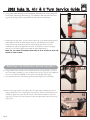
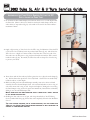
For exploded diagram and part number information, refer to the 2003 Spare Parts Catalog, P/N 950-007563-00.
Contact your local distributor or visit the RockShox website at www.rockshox.com for ordering information.
Information contained in this publication is subject to change at anytime without prior notice.
For the latest technical information, visit our website at www.rockshox.com.
Names used in this manual may be trademarks or registered trademarks of others.
Table of Contents
Tools Needed . . . . . . . . . . . . . . . . . . . . . . . . . . . . . . . . . . . . . . . . . . . . . . . . . . . . . . . . . . . . . . . . . . . . . . . . . . . . . . .2
Remove the Lower Legs . . . . . . . . . . . . . . . . . . . . . . . . . . . . . . . . . . . . . . . . . . . . . . . . . . . . . . . . . . . . . . . . . . . . . .2
Removing the Hydra Air Spring Assembly . . . . . . . . . . . . . . . . . . . . . . . . . . . . . . . . . . . . . . . . . . . . . . . . . . . . . . . .3
Installation of the Hydra Air Spring Assembly . . . . . . . . . . . . . . . . . . . . . . . . . . . . . . . . . . . . . . . . . . . . . . . . . . . .4
Removal and Installation of the U-Turn Spring Assembly . . . . . . . . . . . . . . . . . . . . . . . . . . . . . . . . . . . . . . . . . . .5
Servicing the Pure DeLite Rebound Damper (Duke SL Air and U-Turn . . . . . . . . . . . . . . . . . . . . . . . . . . . . . . . . .6
Installation of the U-Turn Spring Assembly . . . . . . . . . . . . . . . . . . . . . . . . . . . . . . . . . . . . . . . . . . . . . . . . . . . . . .6
Removal of the Internal Floating Piston (IFP) . . . . . . . . . . . . . . . . . . . . . . . . . . . . . . . . . . . . . . . . . . . . . . . . . . . . .7
Assembling the Pure DeLite Damper: Setting the IFP Depth Inside the Pure Tube . . . . . . . . . . . . . . . . . . . . . . .8
Installing the Lower Legs . . . . . . . . . . . . . . . . . . . . . . . . . . . . . . . . . . . . . . . . . . . . . . . . . . . . . . . . . . . . . . . . . . . .10
Warranty . . . . . . . . . . . . . . . . . . . . . . . . . . . . . . . . . . . . . . . . . . . . . . . . . . . . . . . . . . . . . . . . . . . . . . . . . . . . . . . . .11
D u k e S L A i r a n d U - Tu r n
Service Guide
2003 Duke SL Air & U-T
Turn Service Guide
TOOLS NEEDED
• Clean work area
• 5mm and 2.5mm Hex Wrench
• Snap ring pliers
• Plastic Mallet
• Lint Free Rag
• Red Rum
• Isopropyl Alcohol (Spray Bottle)
• Safety Glasses
NOTE: RIGHT
THIS
SIDE EQUALS RIDER'S RIGHT.
•
•
•
•
•
•
•
LEFT
24mm Socket Tool and Wrench
Dental Pick, or sharp pick
300psi Shock Pump (part# 120-004873-00)
Bike Work Stand
Oil Pan
RockShox 5wt or 15wt SL oil
Torque Wrench
SIDE EQUALS RIDER'S LEFT.
SERVICE MAY ALSO BE PERFORMED WHILE THE FORK IS INSTALLED ON THE BICYCLE.
NOTE: THOROUGHLY
READ THIS GUIDE BEFORE PERFORMING SERVICE ON YOUR PRODUCT.
MAY NEED TO REPLACE.
ALWAYS
SEE
THE
2003 SPARE PARTS CATALOG
WEAR SAFETY GLASSES WHEN YOU ARE WORKING ON YOUR FORK!
REMOVE
THE
NOTE
WHAT KIND OF KITS/PARTS YOU
FOR A COMPLETE LIST OF PART
LOWER LEGS
#S
AND EXPLODED VIEWS.
2
1. Remove the air caps from both top caps (Hydra Air positive spring and Pure DeLite air
chamber).
2. Press the schrader valves to release air pressure from both air chambers. Fork should be
completely deflated before disassembly (fig. 2).
3. Remove the rebound adjuster knob by pulling it from the rebound shaft bolt (fig. 3)
4. Place and oil pan below the fork.
5. Using a 5mm hex wrench, loosen the rebound damper shaft bolt (right side) about 3
turns (fig. 4), or half way. Do the same on the air spring/U-Turn shaft bolt (left side).
Do not remove the bolts yet.
2
3
5
2003 DUKE SERVICE GUIDE
2003 Duke SL Air & U-T
Turn Service Guide
6. Using a plastic mallet, firmly tap the rebound damper shaft bolt and air/U-Turn spring shaft
bolt until both shafts are free from lower leg. You will feel the shafts release from the lower
leg press-fit. See Fig 5. With the oil pan below the fork, remove both shaft bolts.
7. Firmly pull lower legs down. You may need to tap the top of the brake arch lightly with a
rubber mallet to release the shafts from the lower leg. Oil will drain into the oil pan.
Using a lint-free rag and isopropyl alcohol, wipe the upper tubes clean of oil and
contamination. Inspect the upper tubes for wear. If anodization is worn from upper
tubes, the crown/steerer/upper tube assembly should be replaced (fig. 7).
NOTE:
5
7
SET THE LOWER LEG ASSEMBLY RIGHT SIDE UP IN AN OIL PAN TO ALLOW THE
EXCESS OIL BATH TO DRAIN.
REMOVING
THE
H Y D R A A I R S P R I N G A S S E M B LY
8. Using a 24mm socket wrench, loosen and remove the air top cap (left side). To remove
the U-Turn spring assembly go to step 18. Inspect the top cap o-ring for wear. Replace if
worn or cut. Clean the underside of the top cap with isopropyl alcohol (fig. 8)
9. You may find removal of the snap ring easier by positioning the fork horizontally.
10. Remove the snap ring from the upper tube: the white spring assembly base plate is
spring-loaded with a wavy washer against the snap ring. Press the white base plate in
toward the upper tube with a flat hex wrench or flat head screwdriver to allow the
snap ring to be removed. Press against the white base plate while removing the snap
ring (fig. 10).
REV. A
8
10
3
2003 Duke SL Air & U-T
Turn Service Guide
11. Pull the shaft and remove the Hydra Air spring assembly from the upper tube (fig. 11)
12. The Hydra Air spring assembly includes the positive air piston, air seal o-ring and
negative coil spring (fig. 12a). Inspect the air seal o-ring for wear and tear. Remove
and replace if needed.
NOTE: REPLACE THE AIR SEAL O-RING
DUKE AIR O-RING SERVICE KIT)
USING KIT
11
12a
#110-006297-00 (02-03
13. Inspect the inner diameter or surface of the upper tube for wear. Clean with
isopropyl alcohol and a lint-free rag. You may need to wrap the clean rag around a
long dowel. Allow cleaned tube to dry.
I N S TA L L AT I O N
OF THE
H Y D R A A I R S P R I N G A S S E M B LY
14. VERY IMPORTANT! After the air seal o-ring has been replaced, apply a light
coating of RockShox 15 wt. oil or RedRum to the o-ring air seal (aids installation).
Proper lubrication of the air seal decreases heat friction, wear and tear, and extends
the life of the seal.
15. Carefully insert the Hydra Air spring assembly into the bottom of the upper tube. Be
sure to push the air piston straight into the upper tube. Use care not to damage the
o-ring on the upper tube machining (Fig. 11).
16. Insert the flat copper colored base ring and wavy washer into the upper tube baseplate step. Next insert the white base plate over the shaft and into the upper tube.
Press firmly against white base plate with a flat hex wrench or flat head screwdriver to
preload the wavy washer spring, and insert the snap ring (sharp end out) with snap
ring pliers. Using a flat head screwdriver, press each side of the snap ring until it
clicks into place (fig. 10).
17. Rotate fork in bike stand to the vertical, upright position. Add 3 cc of 15wt oil or
RockShox RedRum into the positive air chamber (fig. 17). This lubricates the positive
air seal o-ring and protects it from heat friction and wear. Install the air top cap with
a 24mm socket to 50 in-lb.
4
12b
17
2003 DUKE SERVICE GUIDE
2003 Duke SL Air & U-T
Turn Service Guide
REMOVAL AND INSTALLATION OF THE U-TURN SPRING ASSEMBLY
18
18. Using a 2.5mm hex wrench, loosen and remove the U-Turn adjuster knob screw (fig. 18).
19. Gently lift the knob straight up from the top cap hex fitting and remove.
20. Under the knob are three 3/32 ball bearings, each resting on top of a top cap detent
spring (fig. 20a). Remove the ball bearings and springs (fig. 20b).
NOTE: A PEN MAGNET MAY ALSO BE USED TO REMOVE THE BALL BEARINGS AND SPRINGS.
20a
22. Using a 24mm socket wrench, loosen the U-Turn spring top cap, turning
counterclockwise. Unthread completely and pull up on top cap/spring to remove
spring assembly from the upper tube (fig. 22)
23. Removal of U-Turn base plate assembly: Position fork to horizontal position in
bike stand. Using snap ring pliers, remove the base plate snap ring. The U-Turn base
plate assembly will slide out of upper tube. Inspect for damage. See Fig 23a and 23b.
REV. A
20b
22
23a
23b
5
2003 Duke SL Air & U-T
Turn Service Guide
I N S TA L L AT I O N
OF THE
U - T U R N S P R I N G A S S E M B LY
24. Install the base plate assembly and secure with the snap ring, (sharp-side facing) out
of the upper tube (fig. 24).
25. Clean and lubricate the pink spring isolator and U-Turn coil spring with a light
coating of Judy Butter. Insert the spring assembly back into the top of the
crown/upper tube (fig. 22).
26. Press down firmly and hand-thread the U-Turn top cap into the upper tube. Using a
24mm socket wrench, tighten to 50 in-lb (fig. 26).
27. Insert the small detent springs into the top cap, leaving two detent holes in between
each spring. Gently place a ball bearing onto the top of each detent spring (fig 20a).
28. Gently place the U-Turn adjuster knob onto the hex shaft in the center of the UTurn spring assembly top cap. Using a 2.5mm hex wrench torque the adjuster knob
screw to12 in-lb (fig. 18). Do not over-torque, the knob may become damaged.
29. Test the U-Turn adjuster knob for proper installation. The knob should click as it is
turned for proper indexing.
SERVICING THE PURE DELITE REBOUND DAMPER
(DUKE SL AIR AND U-TURN
24
26
31
30. Press the schrader valve on the Pure DeLite air top cap and release any air pressure (fig. 1).
31. Using a 24mm socket tool, loosen and remove the Pure DeLite air top cap from the crown.
Remove the DeLite air top cap by pulling out of the Pure damper tube. Inspect top cap orings for wear, knicks or cuts. Replace as necessary (fig. 31).
32. Using snap ring pliers, remove the Pure DeLite damper base plate snap ring (see fig 32).
6
32
2003 DUKE SERVICE GUIDE
2003 Duke SL Air & U-T
Turn Service Guide
33. Slide the Pure DeLite damper tube assembly from the bottom of the upper tube (fig. 33).
R E M OVA L
OF THE
I N T E R N A L F L O AT I N G P I S T O N ( I F P )
34. Invert the damper and gently but firmly pull the rebound damper seal head from the
Pure tube (The seal head is pressed firmly into the Pure tube and sealed with an oring). You may want to hold a rag around the end of the Pure tube and the seal head
to catch any oil that spills. Turn the Pure tube over and drain the oil into the oil pan
(see fig. 34).
35. To remove the internal floating piston (IFP) hold the Pure tube over a lint-free rag
with one end up . The IFP is located inside the Pure damper tube in the center of
the tube. The IFP is the seal that separates the oil from the air in the Delite air
chamber.
37. Using a long plastic rod, insert the rod into the Pure tube until the rod touches the
underside of the IFP. Make sure the rod engages only the pocketed side of the IFP.
This ensures that you do not damage the inside of the Pure tube with the rod. Press
firmly on the rod only when it is engaged safely into the IFP (fig. 36a). Push firmly
down to release the IFP from the Pure tube (fig. 36b). The IFP will appear at the
end of the tube and on the rag below. (See Fig 36c). Pull the rod out gently without
scratching the inside of the Pure tube.
37. Using isopropyl alcohol clean the inside of the Pure tube with a lint-free rag wrapped
around the rod. Allow to dry.
38. Inspect the IFP o-ring seal for wear and replace as necessary (fig. 39) (110-007425-00
Pure DeLite Internal Floating Piston, or 110-006245-00 Pure Damper Service Kit).
36b
REV. A
36c
33
34
36a
38
7
2003 Duke SL Air & U-T
Turn Service Guide
ASSEMBLING THE PURE DELITE DAMPER: SETTING THE IFP
DEPTH INSIDE THE PURE TUBE
39
39. To assemble the Pure Delite damper, the IFP must first be set to a 6-inch depth inside
the Pure tube. Mount a thin rod or dowel into the bicycle stand clamp or bench vice
with 6 inches of exposed rod (fig. 39). The width of the end of the rod should be a
maximum of 8mm.
40. Apply a light coating of 15wt fork oil to the IFP o-ring for lubrication. Place the IFP
on the end of the rod/dowel, with the pocketed side down (fig. 49). This allows the
IFP to be set to a depth of 6 inches inside of the Pure tube. Place one end of the
Pure tube onto the IFP piston o-ring, and press firmly down until the IFP is seated
inside the tube (fig. 40). Be careful, the Pure tube ends are sharp! Use a lint-free rag
to protect your hands.
41. Press down until the Pure tube end is flat against the vice or bicycle stand clamp (fig.
41). Pull the Pure tube up and off of the rod/dowel. The IFP is now seated firmly
inside the tube at a 6-inch depth.
42. Before installing the Pure rebound damper assembly, remove the white seal head
assembly from the rebound damper shaft. The seal head includes an outer o-ring oil
seal and an inner shaft o-ring oil seal. Inspect and replace if damaged or worn using
the Pure Damper o-ring service kit (part# 110-006245-00). Reinstall the seal head by
sliding it over the rebound damper shaft.
NOTE: LUBRICATE
40
41
THE INNER REBOUND SHAFT O-RING WITH A SMALL AMOUNT
OF OIL BEFORE INSTALLATION.
43. Holding the Pure tube over an oil pan, with the pocketed side of the IFP facing
down (rounded side facing up), fill the tube until completely full with 15wt RockShox
fork oil.
TIP: FOR QUICKER REBOUND, OR IN COLDER
15WT OIL FOR 10 OR 5 WT. LIGHTER WEIGHT
AMOUNT OF COMPRESSION DAMPING.
8
WEATHER, YOU MAY SUBSTITUTE
DAMPING OIL WILL DECREASE THE
2003 DUKE SERVICE GUIDE
2003 Duke SL Air & U-T
Turn Service Guide
44. Gently insert the rebound damper piston head into the oil-filled Pure tube. The oil
will slowly fill the damper valves. Allow enough oil to fill the cavities and top-off the
oil volume until completely full. Gently press down on the white seal head until it
snaps into the Pure tube securely. Your damper is now sealed. (44a and b).
44a
NOTE: PISTON SEAL HEAD MUST BE TOPPED AGAINST REBOUND PISTON.
REBOUND DAMPING SETTING MUST BE OPEN (FULL COUNTERCLOCKWISE).
NOTE: DO
NOT CYCLE THE DAMPER SHAFT UNTIL THE
BEEN INSTALLED AND PRESSURIZED!
DELITE
AIR TOP CAP HAS
45. Slide your Pure Delite oil-filled damper unit into the bottom of the upper (right side
from rider's perspective).
44b
46. Add 3cc/ml of 15wt RockShox fork oil to the top chamber of the Pure Delite
damper (fig. 46). This will lubricate the IFP o-ring. Install the Delite air top cap with
a 24mm socket tool to 50 in-lb and pressurize the chamber 20 to 60 psi with your
shock pump. The IFP is now pressure-set and your damper is sealed.
IMPORTANT: 60
PSI IS THE
MAXIMUM
AIR PRESSURE!
47. IMPORTANT! Insert a 2.5mm hex wrench into the rebound damper shaft end
through the lower leg bolt hole and engage the hex wrench into the inner adjuster rod
hex fitting (fig. 47). Turn clockwise until damper is in the full closed position. This
step will protect the internal damper rod when installing the shaft bolt.
REV. A
46
47
9
2003 Duke SL Air & U-T
Turn Service Guide
INSTALLING THE LOWER LEGS
48. Clean and inspect the dust seals and foam rings. Replace if necessary (Part# 110007250-00). For bushing removal and installation, refer to the Bushing Service Guide
available at www.rockshox.com
49. Saturate the foam rings with 5wt or 15wt fork oil. This will provide lubrication to the
resi wiper and upper tubes when the fork is in use.
50. Gently, slide the lower leg assembly back onto the upper tubes. Be sure the dust seals
do not fold over! Slide the lower leg assembly up just until you feel the lower
bushing touch the bottom of each upper tube. The shaft rods should not be visible
through the shaft bolt holes of the lower leg.
51. Invert the fork in the bicycle stand (90 degrees) with the dropouts facing up. Using
an oil syringe, add 10cc of 5wt RockShox fork oil to the bottom of the fork, through
each of the bolt holes (fig. 51).
52. Slide the lower leg assembly up the fork upper tubes until both the rebound and
air/U-Turn shafts seat through the bolt holes. You may need to use a small hex
wrench to align the shaft ends with the lower leg shaft boltholes. Wipe the bottom
of lower leg ends with a clean rag to remove any excess oil or debris.
53. Clean each black nylon crush washer, inspect for wear and replace if necessary (110005552-00 Crush Washer Kit)(fig. 53). Insert and tighten the clean hollow rebound
damper and solid air/U-Turn shaft bolts. Hand-thread the bolts and tighten with a
5mm hex wrench to 60 in/lb. See Fig 4.
54. Insert the rebound damper external adjuster knob. Adjust to full-close position, and
back off one turn for standard rebound setting. Adjust as necessary to preferred
rebound rate. Cycle the fork to test rebound function.
55. AIR FORKS ONLY: Inflate the positive air chamber to the desired pressure. Install
and tighten the air top cap.
51
53
POSITIVE AIR PRESSURE GUIDELINES
Rider Weight (lb)
<140 (63 kg)
140-160 (63-72 kg)
160-180 (72-81 kg)
180-200 (81-90 kg)
>220 (99 kg)
NOTE: MAXIMUM
AIR PRESSURE IS
180
Air Pressure
80-115 psi
115-130 psi
130-145 psi
145-160 psi
180 psi
PSI.
56. Spray a light coat of isopropyl alcohol on the entire fork, and wipe down with a
clean rag.
10
2003 DUKE SERVICE GUIDE
2003 Duke SL Air & U-T
Turn Service Guide
WARRANTY
RockShox, Inc. warrants its products for a period of two years from original date of purchase to be free from defects in materials or
workmanship. RockShox USA, or an authorized RockShox Agent must inspect all RockShox products. If a product is found by
RockShox or its authorized agent to be defective in materials or workmanship, replacement or repair is at the option of RockShox.
This warranty is the sole and exclusive remedy. RockShox shall not be held liable for any indirect, special, or consequential
damages.
Exclusions of Warranty
This warranty does not apply to products which have not been properly installed and adjusted according to RockShox installation
instructions. The warranty does not cover any product that has been subject to misuse or whose serial number has been altered,
defaced or removed. This warranty does not apply to damage to the product caused by a crash, impact, abuse of the product, noncompliance with manufacturer's specifications, or any other circumstances in which the product has been subjected to forces or loads
beyond its design. This warranty does not cover paint damage or modifications to the product.
Original proof of purchase is required. Warranty repair/replacement is only valid upon presentation of proof of purchase, directly
submitted to RockShox at the time of warranty evaluation. Warranty repair or replacement is at the discretion of RockShox or its
authorized agent, upon physical product evaluation and proof of purchase.
This warranty does not include or cover common 'wear and tear' parts which are subject to damage as a result of normal use, failure to
service product according to RockShox recommendations, wet conditions, racing, use of disc brakes, rider weight, riding or
installation in conditions or applications other than recommended.
'Wear and Tear' parts are identified as: External dust seals, bushings, foam rings, rubber moving parts (such as air sealing o-rings and
glide rings), stripped threaded shafts or bolts, upper tubes (stanchions), rear shock mounting hardware and springs, and fork drop
outs.
Pioneer Support Program
In the event parts are unavailable at the time of your repair, at the option of RockShox or its authorized agent, a replacement fork may
be provided at a determined discount price.
Wa r r a n t y E x p e n s e s I n c u r r e d
The RockShox warranty policy excludes expenses incurred as a result of transportation of product from a RockShox dealer to
RockShox USA, or its authorized distributor, labor performed by a RockShox dealer for removal of RockShox product, or warranty
repair work performed by a RockShox dealer. Warranty work performed by a RockShox dealer is voluntary.
Wa r r a n t y R e pa i r
If for any reason it should be necessary to have warranty work done, return the product to a RockShox dealer. In the USA, dealers are
required to call for a Return Authorization number (RA#) prior to returning product. Outside the USA, dealers are required to call an
authorized RockShox Distributor.
For more technical information, visit our website at www.rockshox.com. For toll-free technical support in the USA, call
1.800.677.7177. Dealers outside the USA must contact their local dealer or distributor. For a complete list of Authorized
Distributors outside the USA, visit www.rockshox.com.
REV. A
11