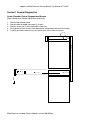
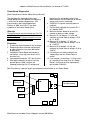
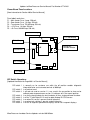
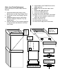
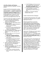
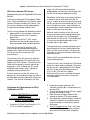
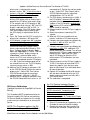
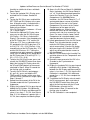
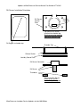
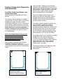
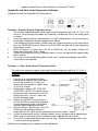
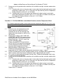
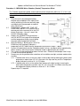
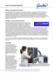
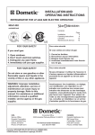
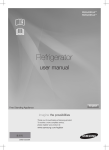
1
Looking for more information?
Visit us on the web at http://www.artisan-scientific.com for more information:
• Price Quotations • Drivers· Technical Specifications. Manuals and Documentation
Artisan Scientific is You~ Source for: Quality New and Certified-Used/Pre:-awned ECJuiflment
• Fast Shipping and DelIve1y
• Tens of Thousands of In-Stock Items
• Equipment Demos
• Hundreds of Manufacturers Supported
• Leasing / Monthly Rentals
Service Center Repairs
Experienced Engineers and Technicians on staff in our
State-of-the-art Full-Service In-House Service Center Facility
• Consignment
InstraView Remote Inspection
Remotely inspect equipment before purchasing with our
Innovative InstraView-website at http://www.instraview.com
We bUy used equipment! We also offer credit for Buy-Backs and Trade-Ins
Sell your excess. underutilized. and idle used equipment. Contact one of our Customer Service Representatives todayl
Talk to a live person: 88EM38-S0URCE fB88-887-68721 I Contact us by email: [email protected] I Visit our website: http://www.artisan-scientific.com
MicroProcessor Incubator Control System
(Revision 060105)
Updates and Revisions
For Service Manual Part Number 97741H01
originally dated November 2002
Contents
Section 1 General Diagnostics
Lower Chamber Control Compartment Access
Power Board Diagnostics
Power Board Fuse Locations
DIP Switch Operations
Water Level Probe Replacement
Section 2 CO2 and RH Diagnostics and Calibrations
Improved CO2 TC Calibrations
Improved CO2 IR Calibrations
Auto Zero Update and Cautions
RH Sensor Causes CO2 Issues
Procedure for Disconnection of RH & Calibration of CO2
RH Sensor Calibrations
Section 3 Temperature Diagnostics and Calibrations
Low Water Jacket Level Causes some Temperature Issues
Updated Air and Water Jacket Temperature Calibration
Updates to MicroProcessor Service Manual Part Number 97741H01
Section 1 General Diagnostics
Lower Chamber Control Compartment Access
[New information for Section 400 of Service Manual]
1.
2.
3.
4.
5.
Remove top chamber cover.
Remove lower chamber front panel (2 screws).
Remove screws for (2) clips retaining the lower tray.
Push portion of extra harness from top electrical compartment into rear wire trough.
Carefully pull lower electrical tray out, avoiding any extra strain on harness.
MicroProcessor Incubator Service Updates revision 060105.doc
Updates to MicroProcessor Service Manual Part Number 97741H01
Power Board Diagnostics
[New information for Section 400 of Service Manual]
These diagnostics are performed to verify
voltage going to the Microprocessor Board that
is necessary for proper temperature & CO2
measurements and solenoid operations.
Displays of “000” and “HELLO” are often
symptoms of the Power Board failing.
Warning:
These procedures require working near live 120
volt AC electricity.
Standard Electrical Safety precautions must be
observed throughout this procedure.
Procedure:
1. Disconnect electrical power to the incubator.
2. Remove top cover of control compartment,
or slide out electrical tray from behind the
display panel.
3. Located the Power Board that includes a
transformer, in the right rear corner of the
electrical tray.
4. Locate board connector “JP6” with ten pins.
5. With digital voltmeter having at least two
decimal places (0.00), measure the
following pin pairings for DC voltage and
compare to the acceptable range listed.
Measurements can be made with or without
the ten-wire harness connected.
6. CAREFULLY connect electrical power to
incubator.
7. Position black voltmeter test lead on Pin 1
or 2 labeled “GND”.
8. Measure each pin below for at least 30
seconds to observe stable voltage.
9. Measure Pin 10 labeled “+12” with red
voltmeter test lead. Normal voltage +12.10
to +11.90 DC.
10. Measure Pin 9 labeled “-12” with red
voltmeter test lead. Normal voltage –12.10
to -11.90 DC.
11. Measure Pin 8 labeled “+5” with red
voltmeter test lead. Normal voltage +5.10 to
4.90 DC.
12. If all voltages are stable and within the
stated range, then this Power Board is
normal.
13. If any voltage is fluctuating +/- 0.10 or more,
or is outside of the range, then this Power
Board is faulty and must be replaced with
part number 31666H01.
See illustration for a general layout and component identification on this Power Board.
Transformer
JP6
Connector
Pin 10
Pin 1
MicroProcessor Incubator Service Updates revision 060105.doc
Board Part
Number location
Updates to MicroProcessor Service Manual Part Number 97741H01
Power Board Fuse Locations
[New information for Section 400 of Service Manual]
Fuse labels and sizes
F1 – Main Heater Fuse, 3 amp, 250 volt;
F2 – Door Heater Fuse, 1.6 Amp, 250 volt:
F3 – Transformer Fuse, 750 Milliamp, 250 volt;
F4 – +12V Fuse, 1.6 Amp, 250 volt;
F5 – +5v Fuse, 800 Milliamp, 250 volt;
F5: 800 Milliamp
F3: 750 Miliamp
F4: 1.6 Amp
Transformer
Board Part
Number location
F2: 1.6 Amp
F1: 3 Amp
DIP Switch Operations
[Updated information for Page 600.1 of Service Manual]
DIP switch 1 is normally on for customer use while the off position enables diagnostic
information to be sent to remote terminal at 9600 bps.
DIP switch 2 is off and not used.
DIP switch 3 is off and not used on version 1.1; was used in the on position to view and or
calibrate water temperature on version 1.0 software: off is the normal position.
DIP switch 4 is on for the top chamber of a dual incubator, off for a single and lower chamber.
DIP switch 5 is off for TC and Digital IR. On only for older Analog IR CO2 Sensors.
DIP switch 6 is on when RH sensor is present, and off otherwise.
DIP switch 7 is on when tank switcher is present, and off otherwise.
DIP switch 8 is off for 10-segment alphanumeric displays and on for 8-segment displays.
MicroProcessor Incubator Service Updates revision 060105.doc
Water Level Probe Replacement
[New information for Section 400 of Service
Manual]
1. Locate and remove two screws at the
bottom corners of the Front Display Panel.
2. Lift and pull on the Front Display Panel to
remove.
3. Locate and remove screws and retainer
brackets holding the Electrical Tray into
Compartment.
4. Slide out Electrical Tray to expose opening
in front left corner that contains the Water
Level Probe.
5. Loosen Water Level Probe Screw to relax
rubber grommet.
6. Remove sensor wire from under screw
head.
7. Remove old rubber grommet.
8. Install new rubber grommet.
9. Install new screw in grommet.
10. Attach new sensor wire under screw head.
11. Tighten screw to compress grommet and
secure the sensor wire.
12. Slide in Electrical Tray.
13. Install retainers and screws.
14. Install Front Display Panel and screws.
Remove Front
Panel and
slide out tray
Water
Probes
Inside
Water
Probe
Relaxed Position
of grommet
Tightened Position
of grommet
Control Tray Top View
Section 2 CO2 and RH
Diagnostics and Calibrations
Improved CO2 TC Calibrations
[Updated information for Page 500.5 of Service
Manual]
1. Locate the CO2/RH Circuit Board (3-1/2” x
4-1/2”) in Control Compartment.
2. Turn off and disconnect the CO2 gas supply
to purge the tubing of all gas.
3. Open the outer and glass doors for 60seconds to remove CO2 from chamber.
4. Close both glass and outer doors. Allow the
chamber to stabilize the temperature and
relative humidity to normal levels in 30 to
60-minutes
5. Read CO2 digital offsets. Press ‘Set Temp’
and ‘Set CO2’ buttons to display and note
the current CO2 offset value. A negative
offset value is indicated with second
decimal, such as “5.6.”. If the offset value is
between - 0.2 and + 0.2 skip next step.
6. Reverse the CO2 offset value. Press the
‘Calibrate’ button twice and adjust the
blinking CO2 display with an amount that is
opposite the CO2 offset value read in Step
5. For example, with a CO2 display of “5.6”
and a positive offset value of “3.2”, the CO2
display is adjusted from “5.6” to “2.4”. In
another example, if the CO2 display shows
“5.6” and a negative offset value of “3.2.”,
the CO2 display is adjusted from “5.6” to
“8.8”.
7. Press ‘Set Temp’ and ‘Set CO2’ to verify the
offset value is between – 0.2 and + 0.2.
8. If CO2 display is larger than “3.0”, complete
an auto-zero with this sequence. If CO2
display is less than 3.0, skip to next step.
Locate and disconnect the door switch
harness connected to Main Board at JP13.
Press ‘Calibrate’ button to display “Auto
Zero” and “Door Open” in ‘Status’. After 30seconds the ‘Status’ display changes to
“Close Door”, reconnect door switch
harness to JP13. In ten minutes or less the
auto zero is completed and the CO2 display
is +/- 0.2. Cycle the incubator power off for
ten-seconds then turn on. The CO2 display
value may be any value +/- 20%.
9. Measure the DC voltage at connector J101
on the CO2/RH Board. Position the red test
probe on pin 1. Adjust R23 “Zero” pot on
CO2/RH Board to make the measured
voltage between - .003 and + .003 DC.
10. Measure the DC voltage at connector J5 on
the CO2/RH Board while the harness is still
connected to J5. Position the red test probe
on pin 1. Adjust R27 “Zero Output” pot on
CO2/RH Board to make the measured
voltage between .297 to .302 DC.
11. The CO2 display should now be +/- 0.2%. If
the CO2 display is between 0.2 and 3.0%,
complete the auto zero sequence from Step
8 above. If the CO2 display is greater than
3.0% then the CO2 sensor and/or CO2/RH
Board should be replaced.
12. Connect and turn on the CO2 gas supply to
15 PSI.
13. Select the customer’s operating CO2
setpoint.
14. Allow the CO2 level to stabilize for tenminutes, and take a CO2 measurement.
15. If display and measurement are different by
less than +/- 0.5% of CO2, the CO2
calibrations are completed.
16. If display and measurement are different by
more than +/- 0.5% CO2, additional CO2
Board calibrations are needed. Turn off and
disconnect the CO2 gas supply to purge the
tubing of all gas. Adjust pot R24 “Gain”
adjust CO2 display to match the CO2
measurement. CO2 calibrations are now
completed.
17. Connect and turn on the CO2 gas supply to
15 PSI. If the display of measured CO2 is
above the setpoint, cycle the glass door
open for 30-seconds, then close both doors
for normal operation.
18. Operate this incubator for 30 to 60 minutes
with the doors closed and verify the CO2
display and measurement are within 0.5%
CO2 of each other.
19. The calibration is completed.
Improved CO2 IR Calibrations
[Updated information for Page 500.5 of Service
Manual]
Updates to MicroProcessor Service Manual Part Number 97741H01
1.
2.
3.
4.
5.
6.
On the incubator display panel, press and
hold the ‘SET CO2%’ button to display
“SET CO2” in the red status window and
use the ‘up or down arrow’ buttons to make
the display in the green CO2% window to
“00.0”.
Turn off and disconnect the CO2 gas
supply from the incubator. Open both doors
and fan the inner door for 60 seconds.
Close both doors.
OR
Disconnect CO2 solenoid at terminal JP18
on the main control board.
Read CO2 display offset. Press and hold
BOTH ‘SET TEMP’ and ‘SET CO2%’
buttons to display “VIEW C OFS” in red
status window and a value in the green
CO2% display window. Note the value in
the CO2% display, including any additional
decimal point in the bottom right corner.
For example, a CO2% display “03.4.”
means negative 3.4% CO2, whereas a
CO2% display of “05.1” means positive
5.1% CO2. Release the buttons.
Remove CO2 display offset. Press and
release the ‘CALIBRATE’ button twice to
make the CO2% display value flash.
Change this value by the negative of the
CO2 offset value found in Step 3.
a. For example, if the CO2% display is
flashing a value of “08.3” and an offset
value of negative 3.4 was found in Step
3, adjust the display from “08.3” to
“11.7” (8.3 – (-3.4) = 11.7).
b. In another example, if the CO2% display
is flashing a value of “04.6” and an
offset value of positive 1.4 was found in
Step 3, adjust the display from “04.6” to
“03.2” (4.6 – 1.4 = 3.2).
Remove the control housing cover (or
display panel of lower unit of dual) to
access the IR CO2 printed circuit board
near the front left corner of the electrical
assembly tray.
Find the black plastic jumper on JP5
terminal (near front left corner) and place it
across the two pins of JP4. On the IR
board, measure for DC volts at terminals
marked COM (or 3) with the black test lead
and Vo (or 2) with the red test lead. Press
and release the up button (near JP4) on
boards marked “V004” [or on newer boards
marked with “V004B” and short the JP1
7.
8.
9.
10.
11.
12.
13.
pins momentarily]. This will force a
measured DC voltage of 0.005 and 0.0%
on the incubator CO2 display (the display
may take up to 2 minutes to display this
change). Remove the jumper from JP4 and
store it on one pin of JP5.
If the front panel CO2% display does NOT
show “00.0”, perform the Auto Zero
procedure in Step 8 below.
If the front panel display is correctly
showing “00.0”, skip down to Step 10.
Verify the CO2 setpoint is at 00.0% (+/- 0.1)
and use a gas analyzer to ensure CO2
content is 0%.
Open the outer door and inner glass door
and press the front panel ‘CALIBRATE’
button to begin the Auto Zero procedure.
Observe in the red status window “AUTO
ZERO”. Close both doors when the red
status window displays “CLOSE DOOR”.
NOTE: The Auto Zero function will last for
five to thirty minutes and will complete
when the “AUTO ZERO” is no longer
displayed in the red status window and the
green CO2% display window resumes
displaying the CO2 content.
Remove the jumper from JP4 and place it
across the two pins of JP3, then press the
up button once (near JP4) on boards
marked “V004” [or on newer boards marked
with “V004B” and short the JP1 pins
momentarily]. This will force a measured
DC voltage of 0.945 at the same terminals
as above and 19.0% on the incubator CO2
display (the display may take up to 2
minutes to display this change). Press the
up or down buttons on the IR board as
required to achieve a 19.0% CO2 display
on the control panel.
Press and release the display panel
‘CALIBRATE’ button twice to make the red
status window display “CALIB CO2”. Press
the display panel ‘up or down arrow’ button
until the green CO2% window displays
“19.0”.
Remove the jumper from JP3 and store it
on one pin of JP5.
Up to this point there has been no CO2 gas
connected to the incubator, the temperature
display is +/- 0.2°C of setpoint, and the
inner glass door has not been opened
(unless the Auto Zero was done in Step 8).
With these conditions met, the CO2 sensor
MicroProcessor Incubator Service Updates revision 060105.doc
Updates to MicroProcessor Service Manual Part Number 97741H01
and interface board can be zeroed as
described below.
14. Verify the CO2 setpoint is at 00.0% and use
a gas analyzer to ensure CO2 content is
0%.
15. Open the outer door and inner glass door
and press the front panel ‘CALIBRATE’
button to begin the Auto Zero procedure.
Observe in the red “AUTO ZERO”.
Close both doors when the red status
window displays “CLOSE DOOR”.
[NOTE: The Auto Zero function will last for
five to thirty minutes and will complete
when the “AUTO ZERO” is no longer
displayed in the red status window and the
green CO2% display window resumes
displaying the CO2 content.]
16. Choose from the two ranges of calibration
procedures listed below, the 0 to 19% (for
use over the range of the incubator) OR at
the specific CO2 % the user will be
operating the incubator.
17. To calibrate for the full range of 0 to 19%
CO2:
a. Reconnect the CO2 gas supply or CO2
solenoid connector to JP18 on the main
control board and set the pressure
regulator to between 10 and 15 PSI.
b. Press and hold the ‘SET CO2%’ button
and use the ‘up arrow’ button to make
the green CO2% display window to
show “10.0”. Allow approximately 10
minutes for the CO2% concentration to
stabilize.
c. Measure the CO2 concentration at the
sample port. If a difference between the
measured sample and the CO2%
display is more than 0.2%, place the
jumper from JP5 on to the two pins of
JP2 and press the up or down buttons
on the CO2 board to make the CO2%
display match the measured sample.
Remove the jumper from JP2 and store
on one pin of JP5.
d. Wait 10 minutes and recheck the
chamber concentration. Readjust per
step ‘c.’ above, if needed.
e. Skip to step 20.
18. To calibrate to a specific CO2 %:
Reconnect the CO2 gas supply or CO2
solenoid and set the pressure regulator to
between 10 and 15 PSI. Press and hold the
‘SET CO2%’ button and use the ‘up arrow’
button to make the green CO2% display
window to show the desired CO2 %. Allow
approximately 10 minutes for the CO2%
concentration to stabilize.
a. Reconnect the CO2 gas supply or CO2
solenoid connector to JP18 on the main
control board and set the pressure
regulator to between 10 and 15 PSI.
b. Press and hold the ‘SET CO2%’ button
and use the ‘up arrow’ button to make
the green CO2% display window to
show the desired CO2%. Allow
approximately 10 minutes for the CO2%
concentration to stabilize.
c. Measure the CO2 concentration at the
sample port. If a difference between the
measured sample and the CO2%
display is more than 0.2%, place the
jumper from JP5 on to the two pins of
JP2 and press the up or down buttons
on the CO2 board to make the CO2%
display match the measured sample.
Remove the jumper from JP2 and store
on one pin of JP5.
d. Wait 10 minutes and recheck the
chamber concentration. Readjust per
step ‘c.’ above, if needed.
19. This concludes the CO2 IR board
calibration procedure. Reinstall panels that
were removed earlier.
20. Additional CO2 calibrations can be done
through the control display.
a. Measure the CO2 content. Compare to
current CO2% display.
b. If a difference greater than 0.2% is
noted, press the “CALIBRATE” button
twice to make the green CO2% window
display to blink.
c. While this display is blinking, press the
up or down arrow button to change the
display to match the sample
measurement value.
d. The control display will return to normal
after fifteen (15) seconds of no button
pushes.
e. The chamber will now equilibrate to the
setpoint based on the corrected
measured value.
MicroProcessor Incubator Service Updates revision 060105.doc
Auto Zero Update and Cautions
[Updated information for Page 500.7 of Service
Manual]
Anytime the CO2 circuit board (with or without
Relative Humidity), it is required to complete the
board calibrations as recorded in procedure 505
or 605 titled "Thermal Conductivity CO2 Printed
Circuit Board Calibration". In addition to this
procedure be aware of that the Auto Zero offset
will be forgotten after any power loss to the
control board. This memory loss affect has
been in the control board firmware since 1993.
Therefore be advised to complete the following
items as part of the 505 or 605 procedure:
1. Cycle the incubator power off and on to
remove the Auto Zero offsets.
2. Establish zero CO2 in the chamber with the
following methods.
a. Select zero CO2 setpoint or disable the
flow of CO2 into the control
compartment.
b. Fan the glass door and allowing at least
30 minutes to recover the temperature
setpoint and humidity levels.
3. View and record the CO2 Display Offsets by
holding the 'SET TEMP' and 'SET CO2'
buttons.
4. Reverse the affect of the CO2 Offset with
the following steps:
a. Access the CO2 display calibration
mode (press 'calibrate' button twice).
b. Cause the CO2 display to remove the
offset amount.
c. For example, with CO2 offset value of
"2.3" and the CO2 display is at "1.4",
you would make this display to become
"0.9." (negative zero point nine).
5. Make measurements and adjustments for
the Zero CO2 on the CO2 board per
Procedure 505 or 605.
6. Observe the CO2 display. This value should
be "0.0". If not check these items:
a. Verify actual CO2 content by analyzing
a sample.
b. Check harness connections to other
boards and sensors, especially the RH
sensor.
c. If the CO2 display is 2.9% or less from
zero complete Auto Zero procedure
(Auto Zero offsets greater than 2.9% will
be forgotten during power cycle.)
d. If the CO2 display is 2.9% or greater,
make adjustments to the R26
potentiometer to make the display to
"0.0".
7. Complete the CO2 Board Calibration
Procedure 505 or 605.
Cautions about Auto Zero Calibrations
We recommend disconnecting the CO2 supply
and purging the tubing of gas pressure prior to
beginning the Autozero.
What may be occurring in a case of an
Autozero problem is the solenoid valve is
allowing some CO2 to leak into the chamber
during the Autozero sequence. This leak could
be from CO2 supply pressure being above the
recommended 15 pounds per square inch (psi),
a defect in the valve that it allows gas to flow
when it is de-energized, or some debris has
gotten into the valve to keep it open.
Note that the CO2 display can show a negative
value when a second decimal point is
illuminated, such as "1.2.". The negative value
does not indicate a true negative measurement
of CO2, rather that the sensor signal is less
than the zero level that calibrations or Autozero
identified as zero CO2.
If some amount of CO2 is measured when the
CO2 display shows 0%, then we recommend
the following test. Disconnect the CO2 supply
and purge the tubing of gas pressure. Open the
glass door for 60 seconds, then close both
doors. Wait 5-minutes and observe the CO2
display. Measure the CO2 environment with
Fyrite. If the display is more than 0.2% CO2, an
Autozero or display calibration may be
necessary. If the CO2 measurement is above
0.5%, then check the Fyrite fluid and the
technique to withdraw the CO2 sample.
Updates to MicroProcessor Service Manual Part Number 97741H01
RH Sensor Causes CO2 Issues
[Updated information for Page 500.5 of Service
Manual]
range. If the RH measured value being
displayed does not reflect this RH change, then
the RH sensor requires diagnostic testing.
In Revco manufactured CO2 Incubators fitted
with a Thermo-Conductivity CO2 Sensor, some
include a Relative Humidity (RH) Sensor. The
RH sensor installation can be confirmed with
the presence of a button labeled “RH%”.
Sometimes the RH error is caused by moisture
or corrosion on the 5-pin terminal of the RH
sensor. Inspect these terminal pins by removing
the RH sensor from the chamber top (3/8” silver
can in the right rear corner, near fan blade), or
by removing the control compartment cover and
view in sensor well near fan motor.
The RH sensor provides the following functions.
• Measured RH in the chamber is shown on
CO2 display while the “RH%” button is
depressed.
• Compensation to the TC CO2 sensor
particularly for low humidity experienced
after the chamber door had been opened.
Moisture and/or corrosion on the RH sensor
terminal can come from the purposed humidity
leak from the chamber via a U-shaped plate
mounted with the RH sensor. The humidity leak
is necessary to avoid condensation on the
chamber walls or glass door.
Since the RH sensor can affect the CO2
measurement being displayed through the
compensation signal, an error or failure of the
RH sensor can cause inaccurate CO2
measurements.
The open end of the ‘humidity leak plate’ could
be mounted such that the humidity would flow
across the RH sensor terminal. The preferred
orientation is to have the humidity to flow away
from the terminals.
The accuracy of the RH sensor can often be
judged by displaying the RH measured value
(depress the ‘RH%’ button). The maximum RH
value that the control system will allow to be
displayed is “96.4”, although the RH sensor
could generate a larger value. Typically an
incubator will only achieve 90%.
Finally, the RH sensor could be worn out and
simply need replacing.
A further simple test of the RH sensor is to
observe this same display during or just after a
chamber door has been opened for at least 30seconds. The RH level should be in the 30%
Procedure for Disconnection of RH &
Calibration of CO2
Used on 300/3000 Series ThermoConductivity (TC)
CO2 Micro-processor Incubators with 8
buttons, including RH%
1. Locate the CO2/RH Circuit Board (3-1/2” x
4-1/2”) in Control Compartment.
The RH sensor is only sold with the CO2 Board
which it has been factory calibrated. Thus when
the RH sensor is replaced with the CO2 Board,
the CO2 system must be calibrated at zero
CO2, at 10% CO2 and user setpoint.
Similarly the RH sensor is checked at ambient
and high humidity levels prior to starting the
CO2 calibrations.
2. Locate and remove jumper on “S3”
(Humidity Interrupt) pins, and place on only
one pin of S3.
3. Turn off and disconnect the CO2 gas supply
to purge the tubing of all gas.
4. Open the outer and glass doors for 60seconds to remove CO2 from chamber.
5. Close both glass and outer doors. Allow the
chamber to stabilize the temperature and
relative humidity to normal levels in 30 to
60-minutes
6. Read CO2 digital offsets. Press ‘Set Temp’
and ‘Set CO2’ buttons to display and note
the current CO2 offset value. A negative
MicroProcessor Incubator Service Updates revision 060105.doc
Updates to MicroProcessor Service Manual Part Number 97741H01
offset value is indicated with second
decimal, such as “5.6.”. If the offset value is
between - 0.2 and + 0.2 skip next step.
7. Reverse the CO2 offset value. Press the
‘Calibrate’ button twice and adjust the
blinking CO2 display with an amount that is
opposite the CO2 offset value read in Step
5. For example, with a CO2 display of “5.6”
and a positive offset value of “3.2”, the CO2
display is adjusted from “5.6” to “2.4”. In
another example, if the CO2 display shows
“5.6” and a negative offset value of “3.2.”,
the CO2 display is adjusted from “5.6” to
“8.8”.
8. Press ‘Set Temp’ and ‘Set CO2’ to verify the
offset value is between – 0.2 and + 0.2.
9. If CO2 display is larger than “3.0”, complete
an auto-zero with this sequence. If CO2
display is less than 3.0, skip to next step.
Locate and disconnect the door switch
harness connected to Main Board at JP13.
Press ‘Calibrate’ button to display “Auto
Zero” and “Door Open” in ‘Status’. After 30seconds the ‘Status’ display changes to
“Close Door”, reconnect door switch
harness to JP13. In ten minutes or less the
auto zero is completed and the CO2 display
is +/- 0.2. Cycle the incubator power off for
ten-seconds then turn on. The CO2 display
value may be any value +/- 20%.
10. Measure the DC voltage at connector J101
on the CO2/RH Board. Position the red test
probe on pin 1. Adjust R23 “Zero” pot on
CO2/RH Board to make the measured
voltage between - .003 and + .003 DC.
11. Measure the DC voltage at connector J5 on
the CO2/RH Board while the harness is still
connected to J5. Position the red test probe
on pin 1. Adjust R27 “Zero Output” pot on
CO2/RH Board to make the measured
voltage between .297 to .302 DC.
12. The CO2 display should now be +/- 0.2%. If
the CO2 display is between 0.2 and 3.0%,
complete the auto zero sequence from Step
8 above. If the CO2 display is greater than
3.0% then the CO2 sensor and/or CO2/RH
Board should be replaced.
13. Connect and turn on the CO2 gas supply to
15 PSI.
14. Select the customer’s operating CO2
setpoint.
15. Allow the CO2 level to stabilize for tenminutes, and take a CO2 measurement.
16. If display and measurement are different by
less than +/- 0.5% of CO2, the CO2
calibrations are completed.
17. If display and measurement are different by
more than +/- 0.5% CO2, additional CO2
Board calibrations are needed. Turn off and
disconnect the CO2 gas supply to purge the
tubing of all gas. Adjust pot R24 “Gain”
adjust CO2 display to match the CO2
measurement. CO2 calibrations are now
completed.
18. Connect and turn on the CO2 gas supply to
15 PSI. If the display of measured CO2 is
above the setpoint, cycle the glass door
open for 30-seconds, then close both doors
for normal operation.
19. Operate this incubator for 30 to 60 minutes
with the doors closed and verify the CO2
display and measurement are within 0.5%
CO2 of each other.
20. The calibration is completed.
RH Sensor Calibrations
the “Full Feature Incubator Service
Manual”, Part Number 97741H01, Rev D.
[Updated information for Page 500.5 of Service
Manual]
This Procedure MUST be performed after the
Relative Humidity (RH) Sensor and matching
RH Sensor Board are replaced, or this can be
used to verify the calibration of an existing RH
Sensor.
NOTE! This Procedure replaces the RH
Calibrations on Pages 400.8 and 500.2 in
NOTE! Accurate Air Temperature in the
Chamber is required to make this RH
Calibration accurate.
If necessary, verify the Air Temperature Display
prior to starting this procedure.
1. Place a Psychrometer or Hygrometer in the
Chamber to measure Relative Humidity.
2. Remove the water from the Humidity Pan
and allow the Incubator Temperature and
MicroProcessor Incubator Service Updates revision 060105.doc
Updates to MicroProcessor Service Manual Part Number 97741H01
3.
4.
5.
6.
7.
8.
9.
Humidity to stabilize for 8 hours with both
Doors closed.
To view the Incubator RH% Display, press
and hold the RH% button. Record this
value.
To view the RH Offset, press and hold the
SET TEMP and RH% buttons at the same
time. A Negative value is indicated with a
second decimal point. Record this value.
Release these buttons.
If this RH Offset value is between – 0.1 and
+ 0.1, skip to Step 8.
Calculate the Adjusted RH Display value
necessary to make the RH Offset to zero
(RH Display – RH Offset = Adjusted RH
Display). For example, if the recorded value
of the RH Display was “27.6” and the RH
Offset was “5.2”, then a subtraction of the
5.2 would adjust the RH Display from 27.6
to 22.4 [27.6 – 5.2 = 22.4]. Similarly, if the
recorded value of the RH Display was “27.6”
and the RH Offset was “5.2.” (where the
second decimal point represents a Negative
value), then an addition of 5.2 would adjust
the RH Display from 27.6 to 32.8 [27.6 – (–
5.2) = 27.6 + 5.2 = 32.8].
To adjust the RH Offset to zero, press and
release the CALIBRATE button three times.
Adjust the flashing RH Display value with
the UP and DOWN buttons to the amount
calculated in Step 5. Allow 15-seconds for
the flashing value to stabilize.
To verify the RH Offset is now between –
0.1 and + 0.1, press and hold the SET
TEMP and RH% buttons at the same time.
If the RH Offset is outside this range, repeat
Steps 5 through 7.
Record the measurement of the RH in the
Chamber made with the Psychrometer or
Hygrometer.
Display the Incubator RH% by pressing and
holding the RH% button. If the difference
between the RH Display and Measured RH
values is less than +/- 2% RH, then Skip to
Step 12. If this difference is greater than +/2% RH, then complete the following Steps.
10. Access the RH Sensor Board. On 300/3000
Series Incubators, the RH Sensor Board is
a 4” x 6” Circuit Board mounted toward the
front of the Electrical Tray in the Control
Compartment. On 500/5000 Series
Incubators, the RH Sensor Board is 2” x 2”
and mounted above a corner of the Main
Control Board in the rear in the Control
Compartment. For access to the Control
Compartment of the upper unit of a
stacked–double or a single Incubator,
remove two screws on the rear and one
screw on each side, then remove the Top
Cover. For access into the Lower Control
Compartment of a stacked–double, see a
separate document for those details.
11. Locate potentiometer R4 on the RH Sensor
Board. Turn this potentiometer screw to
make the RH Display to match the RH
actual measurement. View the RH display
while pressing the RH% button. DO NOT
adjust any other potentiometer screws on
this circuit board.
12. Add DISTILLED Water to the Humidity Pan
and allow 8-hours for the Temperature and
RH to stabilize.
13. Record the measurement of the RH in the
Chamber by the Psychrometer or
Hygrometer.
14. Display the Incubator RH% by pressing and
holding the RH% button. If the difference
between the RH Display and Measured RH
values is less than +/- 2% RH, then the RH
Calibration is completed. If this difference
greater than +/- 2% RH, then complete the
next Step.
15. To calibrate the RH Display value to match
the RH measurement, press and release
the CALIBRATE button three-times and
adjust the flashing value with the UP and
DOWN buttons to match the RH
measurement. Allow 15-seconds for the
flashing value to stabilize.
16. The RH Calibration is now completed.
MicroProcessor Incubator Service Updates revision 060105.doc
Updates to MicroProcessor Service Manual Part Number 97741H01
RH Sensor Installation Orientation
RH Sensor
Control
Plate
Humidity
Connector
Top View of RH Sensor
Installed into chamber top
Showing connector opposite
Opening of humidity plate
RH Sensor in chamber top
Chamber Top
Silicone Gasket
Humidity Control Plate
RH Sensor Connector
RH Sensor
Thumbnuts
Side View of RH Sensor
Installing with gasket
And humidity control plate
MicroProcessor Incubator Service Updates revision 060105.doc
Section 3 Temperature Diagnostics
and Calibrations
Low Water Jacket Level Causes some
Temperature Issues
[New information for Page 500.4 of Service
Manual]
The Condensation of Humidity on Incubator
Chamber Walls and Glass Door is usually from
temperature changes on these surfaces.
Temperature Calibrations Issues, Temperature
Sensor drifting, ambient temperature changes,
heater control failures and even low water in the
Water Jacket may cause these temperature
changes. Diagnostics of each of these Systems
is necessary to identify the specific cause of
this Condensation.
NOTE! The Condensation on these surfaces
may need to be wiped off after ANY
adjustments are made, to verify the
adjustments were successful and the
Condensation does not return.
See the specific Incubator Control System
Calibration Procedures to verify the
Temperature Calibration and Sensors functions.
Checking both the Air and Water Temperature
Probes.
Low Water causing Water
Temperature Probe to
measure Air above the Water
Verify the Room Temperature and Humidity
conditions are maintained at the same level 24hours per day. Verify the Incubator is away from
Heating and Air Conditioning vents, other heat
sources such as space heaters and autodefrost refrigerated units, and windows.
Verify the Incubator Heater functions are
normal to the decisions and signals from the
Incubator Control System. See the specific
Incubator Control System Service Manual to
test these heater functions.
Low Water in Water Jacketed Incubators may
cause the Water Temperature Probe to
measure the air above the water column
instead of the Water Temperature. Because the
Electronic Water Level System may not detect
this low water level, we must verify the water
level in the Water Jacket by attempting to add
water through the Fill Port. See Illustrations.
If more than a few liters of Tap Water are added
through the Fill Port, then the low water
situation is likely causing the Temperature
Issues that lead to the Condensation. Allow the
water temperature in the Water Jacket to
stabilize for up to 8 hours, then check the
Condensation Issue again.
The Electronic Water Level Probe may need
further diagnostics to determine its
effectiveness.
Normal Water Level in
Water Jacket
Updates to MicroProcessor Service Manual Part Number 97741H01
Updated Air and Water Jacket Temperature Calibration
[Updated information for Page 500.4 of Service Manual]
Procedure – Chamber (Display) Temperature Offset
The chamber temperature probe should read the correct temperature within ±0.1°C. If this is not
the case, you will remedy the problem by introducing a temperature offset at the display panel
as follows:
1
Check the probe by placing a thermocouple or an NIST calibrated glass stem thermometer in
the chamber, allowing the chamber temperature to stabilize.
2
If the reading on the thermometer is different from the Temperature display on the control panel,
press the CALIBRATE key once. Observe the CALIB TEMP message and that the temperature
display begins to blink.
3
While the display is blinking, press the UP or DOWN key until the display matches the
temperature measured in Step 1, above.
4
System will automatically exit the Calibration mode if no keys are depressed for approximately
fifteen seconds.
5
The system will now equilibrate based on the new value. Remove thermocouple used in 502.1
and resume normal operation.
Procedure 1 – Water Jacket (Control) Temperature Offset
The water jacket temperature probe should read the correct temperature within ±0.1°C. If this is
not the case, you will remedy the problem by introducing a temperature offset at the display panel
as follows:
1.1
1.2
1.3
1.4
1.5
1.6
Place the tip of a thermocouple halfway
between top and bottom of the water jacket
by inserting it through the Fill Port, and
allowing the thermocouple to stabilize three
(3) to five (5) minutes.
Simultaneously depress SET TEMP, SET
OVERTEMP, and SET CO2; observe that a
decimal point to the extreme left in the CO2
display illuminates – the unit is now in the
System Calibration mode.
Depress the CALIBRATE key three times –
the CAL WATER message will be displayed
and the temperature display (now showing
the water jacket temperature) will blink.
While the display is blinking, press the UP or
DOWN key until the display indicates a
temperature of 0.5°C hotter than the temperature measured in Step 1.1, above.
System will automatically exit the Calibration mode if no keys are depressed for approximately
fifteen seconds, and exit the System Calibration mode in approximately ten minutes.
The system will now equilibrate based on the new value. Remove thermocouple used in step
1.1 and resume normal operation.
MicroProcessor Incubator Service Updates revision 060105.doc
Updates to MicroProcessor Service Manual Part Number 97741H01
1.7
Remove any existing condensation and allow unit to stabilize overnight; evaluate condensation
next day:
1.7.1 If condensation exists on the glass door, increase door heat by lowering the water jacket
temperature: repeat steps 1.2 & 1.3, then press the Up arrow key until the Temperature
display indicates a value of 0 1 - 0.2°C higher.
1.7.2 If condensation exists on the cabinet floor, decrease the door heat by increasing the
water jacket temperature: perform steps 1.2 & 1.3, then press the Down arrow key until
the temperature display indicates a value of 0 1 - 0.2°C lower.
Repeat step 1.7 if required.
Procedure 2 – Full-Size NON-Water Jacket Model Chamber (Control) Temperature Offset
The Chamber temperature probe should read the correct temperature within ±0.1°C. If this is not
the case, you will remedy the problem by introducing a temperature offset at the display panel as
follows:
2.1
2.2
2.3
2.4
2.5
2.6
2.7
Place the tip of a thermocouple one-third
from the top of the cabinet rear wall by
attaching it to the rear wall with tape, and
allowing the thermocouple to stabilize thirty
(30) minutes.
Simultaneously depress SET TEMP, SET
OVERTEMP, and SET CO2; observe that a
decimal point to the extreme left in the CO2
display illuminates – the unit is now in the
System Calibration mode.
Depress the CALIBRATE key three times –
the CAL WATER message will be displayed
and the temperature display (now showing
the water jacket temperature) will blink.
While the display is blinking, press the UP or
DOWN key until the display indicates a
temperature of 0.5°C hotter than the temperature measured in Step 2.1, above.
System will automatically exit the Calibration mode if no keys are depressed for approximately
fifteen seconds, and exit the System Calibration mode in approximately ten minutes.
The system will now equilibrate based on the new value. Remove thermocouple used in step
2.1 and resume normal operation.
Remove any existing condensation and allow unit to stabilize overnight; evaluate condensation
next day:
2.7.1 If condensation exists on the glass door, increase door heat by lowering the water jacket
temperature: repeat steps 2.2 & 2.3, then press the Up arrow key until the Temperature
display indicates a value of 0 1 - 0.2°C higher.
2.7.2 If condensation exists on the cabinet floor, decrease the door heat by increasing the
water jacket temperature: perform steps 2.2 & 2.3, then press the Down arrow key until
the temperature display indicates a value of 0 1 - 0.2°C lower.
Repeat step 2.7 if required.
MicroProcessor Incubator Service Updates revision 060105.doc
Updates to MicroProcessor Service Manual Part Number 97741H01
Procedure 3 – MIDI NON–Water Chamber (Control) Temperature Offset
The Chamber temperature probe should read the correct temperature within ±0.1°C. If this is not
the case, you will remedy the problem by introducing a temperature offset at the display panel as
follows:
3.1
3.2
3.3
3.4
3.5
3.6
3.7
Place the tip of a thermocouple halfway
between top and bottom of the cabinet rear
wall by attaching it to the rear wall with tape,
and allowing the thermocouple to stabilize
thirty (30) minutes.
Simultaneously depress SET TEMP, SET
OVERTEMP, and SET CO2; observe that a
decimal point to the extreme left in the CO2
display illuminates – the unit is now in the
System Calibration mode.
Depress the CALIBRATE key three times –
the CAL WATER message will be displayed
and the temperature display (now showing
the water jacket temperature) will blink.
While the display is blinking, press the UP or
DOWN key until the display indicates a
temperature of 0.5°C hotter than the temperature measured in Step 3.1, above.
System will automatically exit the Calibration mode if no keys are depressed for approximately
fifteen seconds, and exit the System Calibration mode in approximately ten minutes.
The system will now equilibrate based on the new value. Remove thermocouple used in step
3.1 and resume normal operation.
Remove any existing condensation and allow unit to stabilize overnight; evaluate condensation
next day:
3.7.1 If condensation exists on the glass door, increase door heat by lowering the water jacket
temperature: repeat steps 3.2 & 3.3, then press the Up arrow key until the Temperature
display indicates a value of 0 1 - 0.2°C higher.
3.7.2 If condensation exists on the cabinet floor, decrease the door heat by increasing the
water jacket temperature: perform steps 3.2 & 3.3, then press the Down arrow key until
the temperature display indicates a value of 0 1 - 0.2°C lower.
Repeat step 3.7 if required.
MicroProcessor Incubator Service Updates revision 060105.doc
Looking for more information?
Visit us on the web at http://www.artisan-scientific.com for more information:
• Price Quotations • Drivers· Technical Specifications. Manuals and Documentation
Artisan Scientific is You~ Source for: Quality New and Certified-Used/Pre:-awned ECJuiflment
• Fast Shipping and DelIve1y
• Tens of Thousands of In-Stock Items
• Equipment Demos
• Hundreds of Manufacturers Supported
• Leasing / Monthly Rentals
Service Center Repairs
Experienced Engineers and Technicians on staff in our
State-of-the-art Full-Service In-House Service Center Facility
• Consignment
InstraView Remote Inspection
Remotely inspect equipment before purchasing with our
Innovative InstraView-website at http://www.instraview.com
We bUy used equipment! We also offer credit for Buy-Backs and Trade-Ins
Sell your excess. underutilized. and idle used equipment. Contact one of our Customer Service Representatives todayl
Talk to a live person: 88EM38-S0URCE fB88-887-68721 I Contact us by email: [email protected] I Visit our website: http://www.artisan-scientific.com