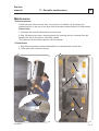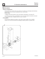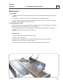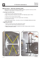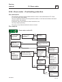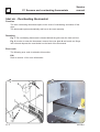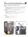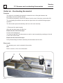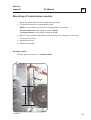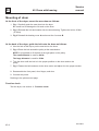
1
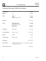
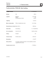
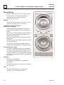
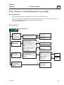
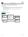
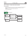
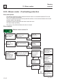
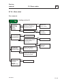
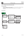
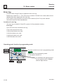
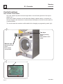
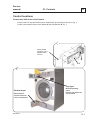
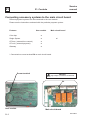
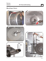
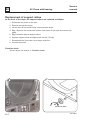
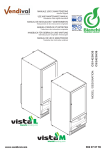
From serial number: 0112 / 0002312 SERVICE MANUAL T3300S TD30•30 Gas heated dryer 487 03 29 21.00 GB WARNING WARNING: For your safety the information in this manual must be followed to minimize the risk of fire or explosion or to prevent property damage, personal injury or death. – Do not store or use gasoline or other flammable vapors and liquids in the vicinity of this or any other appliance. – WHAT TO DO IF YOU SMELL GAS: • Do not try to light any appliance. • Do not touch any electrical switch; do not use any phone in your building. • Clear the room, building or area of all occupants. • Immediately call your gas supplier from a neighbor’s phone. Follow the gas supplier’s instructions. • If you cannot reach your gas supplier, call the fire department. – Installation and service must be performed by a qualified installer, service agency or the gas supplier. Service manual Overview Safety rules 1 Technical data 2 Description of principal components 3 Service Instruction Periodic maintenance 11 Error codes 12 Machine units and components Controls 21 Sensors and overheating thermostats 27 Door and lint drawer 29 Motors - drive and blower 30 Heating - gas 40 Coin meter (see section 21) 41 Drum with bearing 42 Gas system 47 Service manual 1. Safety rules 1 Safety rules This machine is only intended for drying water-washed garments. Clothes that have been cleaned with chemicals/flammable liquids, must NOT be dried in the machine. Remove clothes from the tumble dryer as soon as they are dry. This prevents them from becoming creased, and reduces the risk of spontaneous ignition. The machine must not be used for drying foam rubber or foam-like materials. The machine must not be used for drying floor mops. (This applies only to floor mops containing polypropylene). The machine must not be used by children. The machine must not be hosed down with water. Mechanical, electrical and gas installations must only be carried out by qualified, licensed personnel. Report machine malfunctions to qualified service personnel immediately. This is important for your own safety and for the safety of others. Gas dryers only: The machine is not to be installed in rooms containing cleaning machines with PERCHLORETHYLENE, TRICHLOROETHYLENE or CHLOROFLUOROCONTAINING HYDROCARBONS as cleaning agents. What to do if you smell gas: Do not try to light any appliance. Do not touch any electrical switch; do not use any phone in your building. Evacuate the room, building or area. Contact appropriate authorities. Servicing the dryer Refer servicing to qualified personnel. Improper servicing can result in hazardous conditions, fire, explosion, property damage, and personal injury. Some components may have sharp edges! Wear gloves when handling mechanical components. 487 0329 21 1.1 Service manual 2 2. Technical data Contents Technical data type 3300S - gas heating 2.2 Technical data type TD30•30 - gas heating 2.3 487 0329 21 2.1 2 Service manual 2. Technical data Technical data, type 3300S, Gas heating Drum volume: 2 x 300 litre Weight: Net Drum: Diameter Depth Revolutions per minute Capacity: Motor: 282 kg 760 mm 660 mm 45 rpm 2 x 13.6 kg Effect without reverse Effect with reverse Revolutions per minute Motor 50 Hz Motor 60 Hz 2700 rpm 3200 rpm Heat effect: Gas heating 2 x 21 kW Air consumption: Gas 2 x 21 kW Piping: Exhaust Ø 200 Pressure drop: Exhaust (max.) 90 Pa Gas piping: Gas pressure: Sound pressure level: 2.2 2 x 1 kW 2 x 1 kW 2 x 650 m3/h ISO 7/1-R1/2 See page regarding pressure in the installation manual supplied with the dryer < 70 dB (A) 487 0329 21 Service manual 2 2. Technical data Technical data, TD30•30, Gas heating Cylinder volume: 2 x 10.6 cu.ft. Weight: Net Cylinder: Diameter Depth Revolutions per minute Capacity: Motor single phase: 620 lb 29 15/16” 26” 45 rpm 2 x 30 lb Effect of cylinder/vent motor Revolutions per minute: Motor 60 Hz 2 x 0.54 hp 3200 rpm Heat effect: Gas heating 2 x 71600 BTU/h Air consumption: Gas 2x 21 kW 2x383 cu.ft/min Piping: Exhaust Pressure drop: Exhaust (max.) Gas piping: Gas pressure: Sound pressure level: 487 0329 21 ø8” 0.35”W.C 1/2” NPT See page regarding pressure in the installation manual supplied with the dryer < 70 dB (A) 2.3 2 2.4 2. Technical data Service manual 487 0329 21 Service manual 3. Description of principal components 3 Contents Description 487 0329 21 3.2 3.1 3 3. Description of principal components Service manual Description Dryer T3300S or TD30•30 is a stack dryer. The dryer has 2 independent pockets. Each pocket has a drum volume of 300 litres (10.6 cu.ft). Motors The dryer has 2 motors per pocket - one to run the drum and one to run the fan. Programs, Selecta Control (Non-Coin version) Each pocket has an independent operating panel and an independent main control circuit board. On OPL (non-coin operated) models, there are five factory-provided drying programs in the dryer control’s memory. It is also possible to directly select the desired drying time. The dryer stops automatically when the clothes are dry (Auto Stop). The dryer’s control provides diagnostic error codes which offer guidance in troubleshooting. Coin drop/card reader The dryer is available with a factory-installed coin drop, a factory-installed card-start system, or it can be prepared for field installation of a card start system. On vending models, insertion of a coin or card vends an owner- programmed drying time. Heating The dryer is gas heated. The standard configuraion is equipped for natural gas. An LPG (bottle gas) conversion kit is available see section 40. Use The dryer is designed for coin-operated laundries or on premises laundries. 3.2 487 0329 21 Service manual 11 11. Periodic maintenance Contents Function check 11.2 Maintenance: Exhaust plenum, perforations 11.3 Maintenance: Blower compartment, door gasket 11.4 Maintenance: Secondary lint screen 11.5 Maintenance: Internal wearing parts 11.6 The area surrounding the dryer 11.7 Safety and warnings signs (USA only) 11.7 487 0329 21 11.1 11 11. Periodic maintenance Service manual Function check Check that the drum is empty and the loading door is closed. Checking the micro switches Start the dryer. Check if the micro switches are working properly: • The dryer must stop if the loading door is opened. If the dryer operates with the loading door open, go to section 29. • The dryer must stop when the lint drawer is opened. If the dryer operates with the lint drawer open, go to section 29. Correct direction of rotation For dryers with a 3-phased motor the direction of rotation must be checked. Check the direction of rotation of the blower motor: 1. Fig. 1 Correct direction of rotation must be clockwise when viewed through the ventillation holes on the motor cover on the rear of the dryer. If the direction of rotation is not correct, swap two phases on the power input connection terminal block. Final test 1. Start the dryer and allow it to operate for 5 minutes on a program that requires heat. 2. Check whether the heating is working by opening the loading door and feeling the heat. If the above test-points are in order, the dryer is ready for use. 1 11.2 487 0329 21 Service manual 11 11. Periodic maintenance Maintenance • Exhaust plenum Check that (after three months, then every three to six months, as necessary) the exhaust plenum on the rear of the dryer has not become blocked with lint or other debris. Dismounting 1. Dismount the external exhaust duct from the dryer. 2. Fig. 1 Dismount the dryer's exhaust plenum by removing the two screws A from the flange at the top of the plenum, and lifting it away. The inside part of the exhaust plenum can be cleaned. • Perforations 1. Fig. 2 Check (weekly) that perforations B are not blocked with lint and dust. 2. Clean them with a vacuum cleaner. 1 2 B B A B 487 0329 21 B 11.3 11 11. Periodic maintenance Service manual Maintenance • Blower compartment Check (after three months, then every three to six months, as necessary) that the blower compartment has not become blocked with lint or other debris. Dismounting 1a. Fig.1 Dismount the blower to get to the blower compartment, see section 30. 1b. If the dryer has a heavy accumulation of lint, the exhaust plenum should be removed The top of the blower compartment A can now be cleaned. • Door gasket Check that the loading door gasket is clean and in good condition. Use a suitable cleaner. Do not use solvents that may damage sensitive plastics or painted finish. 1 A 11.4 487 0329 21 Service manual 11 11. Periodic maintenance Maintenance • Lint drawer 1. Check (at least once daily) that the lint screen in the drawer B is clean and in good condition. 2. Remember to clean the lint drawer in both the top and bottom dryers! 3. Clean the lint drawer gaskets. Use a suitable cleaner. Do not use solvents that may damage sensitive plastics or painted finish. • Secondary lint screen Check (at least every other day) that the secondary lint screen A behind the lint drawer B has not become blocked with lint or other debris. The secondary lint screen A is essential for reducing lint accumulation in the blower. ALWAYS reinstall this screen after cleaning it! Dismounting 1. Remove the screen drawer B from the dryer. 2. Remove the 2 wing nuts. 3. Remove the secondary lint screen A and clean the screen and the area C behind the screen by using a vacuum cleaner. 4. Remember to clean the lint screens in both the top and bottom dryers! A C B 487 0329 21 11.5 11 11. Periodic maintenance Service manual Maintenance - Internal wearing parts Maintenance should be conducted to an extent related to operation frequency and the conditions on the premises, or at least once a year. • Cleaning around the drum 1. Disconnect the power supply from the dryer. 2. Fig. 1 Dismount the front panel (See section 42: Replacing support rollers). 3. Remove the lint using a vacuum cleaner. 4. Inspect the two support rollers and replace them if necessary. 5. Re-assemble the dryer. 6. Connect the power supply - remember to carry out a function check as decribed earlier in this section. • Tightening drive belt 1. Remove the plate in front of the transmission module. (See section 30: Dismounting transmission module). 2. Fig. 2 Check that the springs are tightend as shown. Spring length x should be 130 mm ±5 mm (5” ± 3/16”). 1 2 A x Clean all accumulated lint 11.6 487 0329 21 Service manual 11. Periodic maintenance 11 The area surrounding the dryer Fresh-air intake to the room Check that the fresh-air intake to the room and the exhaust ducts/pipes from the room are not clogged by lint/dust or blocked in any other way. Dryer area Check that the dryer area is clear and free from combustible materials, gasoline and other flammable vapours and liquids. Safety and warnings signs (USA only) Product safety signs or labels should be replaced when they no longer meet the legibility requirements for safe viewing. Check that all the safety and warning signs are located on the dryer as shown in the installation manual supplied with the dryer. A copy of this manual is available from your dealer. Replacement of safety signs or labels should be in accordance with the installation manual. 487 0329 21 11.7 11 11.8 11. Periodic maintenance Service manual 487 0329 21 Service manual 12 12. Error codes Contents Error codes Overwiew E 01 - E 08 12.2 Error codes Overwiew E 09 - E 99 12.3 Important service note 12.4 Troubleshooting 12.5-12.25 Check-list - E01, E02, E08 and E15 12.26 The heating indicator on a electric heated dryer is on 12.27 Error log 12.28 487 0329 21 12.1 12 Service manual 12. Error codes Error codes - Overview E 01 - E 18 and E 99 The dryer is equipped with an automatic diagnostic system. Operating problems are displayed as blinking error codes. Whenever an error occurs, the dryer stops operating. Except where noted, error codes are cleared by disconnecting the power or by entering the service program. Error analysis An diagnostic procedure is provided for each error code. If an error has not been corrected after the procedure, please contact the manufacturer for additional assistance. Error code E 01 Decription Page General note regarding error codes related to overheating (E01, E02, E08) 12.4 Inlet air (electric heated dryer only) - input temperature is too high The temperature of the air entering the drum is too high (measured by thermistor element). 12.5 Inlet air (gas heated dryer only) - input temperature is too high The temperature of the air entering the drum is too high (measured by thermistor element). 12.6 E 02 Outlet air - Output temperature is too high 12.7 The temperature of the air leaving the drum is too high (measured by thermistor element). E 03 Inlet air - Sensor has short-circuited The thermistor element measuring the air inlet temperature to the drum, or the wiring to the sensor has shorted. 12.8 E 04 Outlet air - Sensor has short-circuited The thermistor element measuring the air outlet temperature from the drum, or the wiring to the sensor has shorted. 12.9 E 05 Blower motor –The thermal protection switch in the motor, or its harness, is open. 12.10 E 06 Drum motor – The thermal protection switch in the motor, or its harness, is open. 12.11 E 07 Not in use on this model. E 08 Inlet and Outlet air protection thermostats One of the proctection thermostats has opened due to overheating. E 08 check list 12.2 12.12-12.14 12.26 487 0329 21 Service manual 12. Error codes 12 Error code Decription E 09 Not in use on this model. E 10 Setting - Programming error / incorrect or missing parameter(s). E 11 Not in use on this model E 12 Drying error - Maximum allowable Autostop time exceeded (non-coin operated models only) 12.16 Drying error - Requested drying time is longer than maximum allowed. (dryer connected to a payment system) 12.17 E 14 Gas error - A flame was not detected on gas heated dryers 12.18 E 15 Vacuum switch The vacuum switch does not shut within 5 seconds after the dryer is started. 12.20 E 15 check list 12.26 E 16 Vacuum switch The vacuum switch was already closed when an attempt to start the dryer was made. 12.20 E 17 Input sensor disconnected The inlet thermistor or wiring to the thermistor is open. 12.21 E 18 Output sensor disconnected The outlet thermistor or wiring to the thermistor is open. 12.22 E 99 Communication error The usermodule does not recieve communication from the main board. (user module and main board). E 13 487 0329 21 Page 12.15 12.23 12.3 12 12. Error codes Service manual IMPORTANT SERVICE NOTE! Continuity and resistance measurements suggested by the procedures in this manual require that power to the dryer be disconnected, and that the device whose resistance is being measured be disconnected from all circuits that might affect the accuracy of the measurement. E 01, E 02, E 08 General note regarding error codes related to overheating: Before troubleshooting the electronic systems of the machine, examine the dryer to determine if the airflow is normal. Insufficient airflow due to over-filling the machine, lint-obstructed screens, air passages and ducts, or improper exhaust venting are all possible causes of various errors. See page 12.26. 12.4 487 0329 21 Service manual 12 12. Error codes E 01 - Inlet air - Input temperature is too high, electric heated dryer Error description The input temperature exceeds 85°C (185°F) for more than 10 sec. The air thermistor is a "negative temperature coefficient" (NTC) sensor. As a result of this the resistance decreases as its temperature increases. The dryer stop operating. Error analysis See section 27 2. Defective NTC sensor? NO Go to step 2. Disconnect NTC sensor at its terminal-block YES connection to dryer wiring Go to step 3. harness and measure the resistance on the NTC Replace NTC sensor. NO sensor. Is the resistance between 100 kΩ and 120 kΩ at (Section 27) 20°C (68°F)? Measure resistance between P18-1 and P18-2 on main circuit board. Is the circuit open (infinite resistance)? Disconnect NTC sensor at its terminal-block connection to dryer wiring harness. 4. Too high heating effect? El ec tr ic he at ed 3. Defective NTC harness from the check list. Are there any errors according to the list? no ty et av ai la bl e See check list on page 12.26 YES Correct the error dr ye ri s 1. Missing air flow. Is the measured electric effect correct according to the data sign? YES NO YES Go to step 4. NO Replace harness Go to step 5. Are the rated output and the connection on the heating units okay? NO YES Change when necessary. Go to step 5 5. Defective NTC interface on main circuit board. YES Replace the main circuit board. (Section 21) For instructions on entering programming mode see section 21. 487 0329 21 12.5 12 Service manual 12. Error codes E 01 - Inlet air - Input temperature is too high, gas heated dryer Error description The input temperature exceeds 220°C (428°F) for more than 10 sec. The air thermistor is a "negative temperature coefficient" (NTC) sensor. As a result of this the resistance decreases as its temperature increases. The dryer stop operating. Error analysis See section 27 1. Missing air flow. See check list on page 12.26 2. Defective NTC sensor? 3. Defective NTC harness. 4. Burner power too high? YES Correct the error Are there any errors according to the list? from the check list. NO Go to step 2. Disconnect NTC sensor at its terminal-block YES connection to dryer wiring Go to step 3. harness and mesure the resistance on the NTC Replace NTC sensor. NO sensor. Is the resistance between (Section 27) 100 kΩ and 120 kΩ at 20°C (68°F)? Measure resistance between P18-1 and P18-2 on main circuit board at room temperature. Is the circuit open (infinite resistance)? Disconnect NTC sensor at its terminal-block connection to dryer wiring harness. Is the nozzle and the nozzle pressure correct according to the gas type printed on the data sign? YES NO YES Go to step 4. NO Replace harness Go to step 5. Replace the nozzle and adjust the nozzle pressure. (Installation manual) 5. Defective NTC interface on main circuit board. YES Replace the main circuit board. (Section 21) For instructions on entering programming mode see section 21. 12.6 487 0329 21 Service manual 12 12. Error codes E 02 - Outlet air - Output temperature is too high Error description The output temperature exceeds 85°C (185°F) for more than 30 sec. The air thermistor is a "negative temperature coefficient" ( "NTC") sensor. As a result of this the resistance decreases as its temperature increases. The dryer stop operating. Error analysis See section 27 1. Missing air flow. See check list on page 12.26 2. Defective NTC sensor? 3. Defective NTC harness 4. Defective NTC interface on main circuit board. 487 0329 21 YES Correct the error from Are there any errors according to the list? the check list. NO Go to step 2. Disconnect NTC sensor at its terminal-block connection to dryer wiring YES harness and mesure the resistance on the NTC sensor NO Is the resistance between 100 kΩ and 120 kΩ at 20°C (68°F)? Disconnect NTC sensor at its terminal-block connection to dryer wiring harness. Go to step 3. Replace NTC sensor. (Section 27) Measure resistance between P18-3 and P18-4 on main circuit board. Is the circuit open (infinite resistance)? YES Go to step 4. NO Replace harness YES Replace the main circuit board. (Section 21) 12.7 12 12. Error codes Service manual E 03 - Inlet air - Sensor has short-circuited Error description This error code indicates that the inlet air thermistor, connected to P18-1 and P18-2 on the main circuit board, or the harness from the main circuit board circuit board to the thermistor, has short circuited. A defective detection circuit in the main circuit board can also cause this error. The dryer stops operating. Error analysis See section 27 1. Defective NTC sensor or harness? 2. Defective NTC interface on main circuit board. 12.8 Measure the resistance of the NTC sensor and harness between P18-1 and P18-2 on the main circuit board. Is the resistance between 100 kΩ and 120 kΩ at 20°C (68°F)? YES NO Go to step 2. Replace NTC sensor or harness. (Section 27) YES Replace the main circuit board. (Section 21) 487 0329 21 Service manual 12 12. Error codes E 04 - Outlet air - Sensor has short-circuited Error description This error code indicates that the outlet air thermistor, connected to P18-3 and P18-4 of the main circuit board, or the harness from the board to the thermistor, has short circuited. A defective main circuit board can also cause this error. The dryer stops operating. Error analysis See section 27 1. Defective NTC sensor or harness? 2. Defective NTC interface on main circuit board. 487 0329 21 Measure the resistance of the NTC sensor and harness between P18-3 and P18-4 on main citcuit board. Is the resistance between 100 kΩ and 120 kΩ at 20°C (68°F)? YES NO Go to step 2. Replace NTC sensor or harness. (Section 27) YES Replace the main circuit board (Section 21) 12.9 12 Service manual 12. Error codes E 05 - Blower motor - Overheating protection Error description The thermal protection switch inside the blower motor is connected between P6-2 and P6-5 of the main circuit board. This error indicates that the thermal protection switch, or the harness between the board and the switch, has opened. A defective main circuit board can also cause this error. The dryer stops operating. The error is only detected when the door is closed. Error analysis Blower motor section 30 1. Is the motor very warm? Are the vent holes in the motor cover obstructed? YES Clean the perforations. NO 2. Does the motor run slowly or is it locked? Go to step 2. Replace motor Is the motor seized? YES or clear blockage NO Go to step 3. Connect P6. 3. Unplug motor control connector P6 from the main circuit board. Is there continuity between P6-2 and P6-5 in the harness plug? YES Does the error reoccur when the motor is restarted? NO The error occurs immediately. YES Replace the main circuit board YES Put the dryer back into operation. NO Check motor Is the motor cold? YES harness and connector. Replace motor/harness/ connector. NO 12.10 The error occurs after a while’s operation. Defective motor protection replace the blower motor. Wait until the motor is cold and restart it. 487 0329 21 Service manual 12 12. Error codes E 06 - Drum motor - Overheating protection Error description The thermal protection switch inside the drum motor is connected between P7-5 and P7-6 of the main circuit board. This error indicates that the thermal protection switch, or the harness between the board and the switch, has opened. A defective main circuit board can also cause this error. The dryer stops operating. The error is only detected when the door is closed. Error analysis Drum motor section 30 1. Is the motor very warm? Are the vent holes in the motor cover obstructed? YES Clean the perforations. NO 2. Does the motor run slowly or is the rotor locked? Replace motor or correct reason for mechanical overload. YES NO 3. Unplug motor control connector P7 from the main circuit board. Is there continuity between P7-5 and P7-6 in the harness plug? Go to step 2. Go to step 3. YES Connect P7. Does the error reoccur when the motor is restarted? The error occurs immediately. YES Replace the main circuit board YES NO Put the dryer back into operation. NO Is the motor cold? YES NO 487 0329 21 The error occurs after a while’s operation. Defective motor protectioncircuit replace the blower motor or harness. Check motor harness and connector. Replace motor/harness/ connector. Wait until the motor is cold and restart it. 12.11 12 12. Error codes Service manual E 08 - Inlet air and outlet air - Overheating thermostat Error description Two normally-closed, manual-reset high limit thermostats, one measuring the inlet air temperature, and one measuring the outlet air temperature, are connected in series between P4-6 and P4-10 of the main circuit board. This error indicates that one of the two thermostats, or the connecting harness has opened. A defective main circuit board can also cause this error. The dryer stops operating. The error is only detected when the door is closed. Error analysis Overheating thermostat section 27 YES Replace the fuse and 1. Has fuse F3 blown? 2. Disconnect P4 from the main circuit board. Check for continuity between pin 6 and pin 10. Is the circuit closed? 2. Has the high-limit protection thermostat near the heating unit tripped? 3. Has the high-limit protection thermostat near the blower tripped? 12.12 restart the dryer. NO Go to step 2. YES Replace main circuit board. NO YES NO YES NO Go to step 3. See Inlet air. Go to step 3. See Outlet air. Check for bad connections in thermostat(s) or harness and replace as appropriate. 487 0329 21 Service manual 12 12. Error codes E 08 - Inlet air - Overheating thermostat Inlet air YES 1. Missing air flow. See check list on page 12.26 2. Check the door gasket and internal sealings against the drum. Correct the error from the check list. Are there any errors according to the list? NO YES Is the door gasket or sealings defective / missing / dirty? Go to step 2. Replace as appropriate. NO Go to step 3. 3. Check the inlet temperature. (Factory setting) Is the inlet temperature parameter set correctly? (Programming Selecta Control) Is the inlet sensor YES placed correctly in the inlet air flow (behind the drum). YES Replace main circuit board. NO NO 487 0329 21 Enter the programming mode and adjust the inlet temperature setting. Correct the possition of the sensor. 12.13 12 Service manual 12. Error codes E 08 - Outlet air - Overheating thermostat Outlet air 1. Missing air flow. Are there any errors according to the list? See check list on page 12.26 YES NO 2. Is the outlet sensor placed correctly in the outlet air flow? Go to step 2. YES Replace the main circuit board. NO 12.14 Correct the error from the check list. Correct the position of the sensor. 487 0329 21 Service manual 12 12. Error codes E 10 - Programming errors - Settings Error description This error occurs when the parameter set-up is inconsistent. Note! When resetting the circuit board the user adjusted programs disappear and need reprogramming. The dryer stop operating. Error analysis 1.Enter the service program. Set parameter 4.06 to "1" to restore all factory settings. Exit service program and attempt to operate the dryer. 487 0329 21 YES Replace the main circuit board Does the E10 return? NO Re-enter user-desired parameter settings (time per push/coin, for example). These are erased when factory defaults are restored. 12.15 12 Service manual 12. Error codes E 12 - Drying error with Auto Stop system Error description Non-coin metered models only: The dryer stops automatically when the clothes are dry (Auto Stop system). Error code E12 occurs if the Auto Stop system does not register that the clothes are dry within 90 minutes (factory setting). Error analysis YES 1. Is the dryer cold? NO 2. Is the dryer overfilled with clothes? NO Has the heating been insufficient due to a blown fuse or other reason? YES Go to step 2 Go to step 2. Replace the fuses or repair heating unit and restart. YES Remove some of the clothes and restart? NO Check factory setting for Auto Stop , max drying time. (Programming Selecta Control) Resetting Resetting is done by opening/closeing the door to the dryer and press the start button once, or by pushing the start button twice. 12.16 487 0329 21 Service manual 12 12. Error codes E 13 - Drying error, dryer connected to a payment system Error description Error code E13 occurs with Payment systems where the customer or system has requested a longer drying time than the allowed 90 minutes (factorry setting on the dryer). Error analysis 1. Is the YES Check that there are no errors on the connected connection payment systemor harness between and correct these. UM P1-1 (user module) and UM P1-3 (payment system) NO Incorrect payment system disconnected? set-up (max. 90 min.) or defective user module. Resetting Resetting is done by opening/closeing the door to the dryer and press the start button once, or by pushing the start button twice. 487 0329 21 12.17 12 Service manual 12. Error codes E 14 - Gas error Error description When the ignition control fails to detect a flame, a signal is sent to the main circuit board, and error code E14 is displayed. The metal probe of the flame sensor generates an electrical current when exposed to the burner's flame. This signal is detected by the ignition control module which, in turn, cuts off the gas valve immediately .If the sensor does not indicate flame within 5 sec. The integrity of the sensor's electrical connection is, therfore, critical to proper operation of this system. Displaying error code E14 USA and Japan: The error code is not displayed until the 3rd unsuccessful ignition attempt. Europe: The error code is displayed at the 1st unsuccessful ignition attempt. Resetting NOTE! When resetting the system the dryer must operate on a program with heat and when the heat indicator is on. Resetting is done by pushing the gas reset button on the user module, see section 40. Japan only: By opening and closing the door. Heat indicator P 487 19 24 03.01 12.18 487 0329 21 Service manual 12 12. Error codes E 14 - Gas error Error analysis Heating section 40 1. Is there a short-lived flame at the ignition attempt? YES Is the flame sensor placed in the flame / is the sensor's electrical connection okay? YES Replace the Go to step 2. NO ignition control. NO YES 2. Is an ignition spark present? NO Go to step 3. Is the ignition electrode placed correctly / is the connection okay? (Section 40) YES NO 3. Is the gas supply/nozzle pressure okay? Adjust / clean the electrode / connections. Go to step 3. Adjust / clean / replace the electrode. YES Replace the ignition control or gas valve. NO Ventilate the gas system / contact gas supplier. 4. Is the air reducing plate mounted. NO Mount the plate. (France, Belgium only) 487 0329 21 12.19 12 12. Error codes Service manual Intentionally blank 12.20 487 0329 21 Service manual 12 12. Error codes E 15 - Vacuum switch Error description The vacuum switch does not shut within 5 seconds after the fan has started. Error analysis 1. Does the vacuum shutter plate close against the body of the dryer within 5 seconds after the dryer is started? 2. Manually close the vacuum shutter plate. Disconnect P16 from the main circuit board and check for continuity between P16.1 and P16.2. YES Is the electric switch activated when the shutter plate closes? YES Go to step 2. NO NO Go to step 3. Adjust / replace the switch or the shutter plate. YES Replace main circuit board. YES Is the circuit closed? NO Go to step 3. YES Go to step 4. 3. Does the blower motor rotate in the correct direction? (Section 11) 4. Is the air flow obstructed? NO NO Check the motor’s connection and phase order. See check list on page 12.26 and correct airflow problem as appropriate. Resetting Resetting is done by opening/closeing the door to the dryer and press the start button once, or by pushing the start button twice. 487 0329 21 12.21 12 12. Error codes Service manual E 16 - Vacuum switch does not open Error description The error occurs if the vacuum switch is already closed when an attempt to start the dryer is made. Error analysis 1. Can the vacuum shutter plate move freely? YES NO 2 Disconnect one wire from the vacuum switch. Check continuty of the switch. Does it open when the shutter plate moves away from the dryer cabinet? 3. Disconnect P16 from the main circuit board. Check continuity between P16.1 and P16.2. Is the circuit closed? YES NO YES NO Go to step 2. Repair shutter plate mechanism. Go to step 3. Replace or adjust vacuum switch, as necessary. Replace vacuum switch harness. Replace main citcuit board Resetting Resetting is done by opening/closeing the door to the dryer and press the start button once, or by pushing the start button twice. 12.22 487 0329 21 Service manual 12 12. Error codes E 17 - Input sensor disconnected Error description This error is displayed when the inlet NTC sensor is disconnected or indicates less than 30°C (86°F) after 2 min. of dryer operation. However, if the sensor is disconnected during operation the error is displayed immediately. Error analysis 1. Defective NTC sensor/harness? Electric heated dryers only Measure the resistance on YES the NTC sensor between Go to step 3. P18-1 and P18-2 on main circuit board. Is the resistance between NO Replace NTC sensor or harness. 100 kΩ and 120 kΩ at 20°C (68°F)? (Section 27) 2. Has the heating been insufficient due to blown fuse or other reasons? YES NO Replace fuse or repair heating unit. Go to step 3. 3. Defective NTC interface on main circuit board. Replace board. 487 0329 21 12.23 12 Service manual 12. Error codes E 18 - Output sensor disconnected Error description This error is displayed when the outlet NTC sensor is disconnected or indicates less than 20°C (68°F) after 2 min. of dryer operation. However, if the sensor is disconnected during operation the error is displayed immediately. Error analysis 1. Defective NTC sensor/harness? Electric heated dryers only Measure the resistance on YES the NTC sensor between Go to step 2. P18-3 and P18-4 on main circuit board. Is the resistance between NO Replace NTC sensor or harness. 100 kΩ and 120 kΩ at 20°C (68°F)? (Section 27) 2. Has the heating been insufficient due to blown fuse or other reasons? YES NO Replace fuse or repair heating unit. Go to step 3. 3. Defective NTC interface on main circuit board. Replace board. 12.24 487 0329 21 Service manual 12. Error codes 12 E 99 - Communication error Error description This error occurs when the user module circuit board does not communicate with the main circuit board via their serial interface. This error does not get registered in the error log. Error analysis 1. Is the connection between the user module and the main circuit board correct? YES Go to step 2. NO Establish the connection. 2. Replace the main circuit board or the user module circuit board. Resetting Resetting is done by either disconnecting the power or by entering the programming mode. How to enter the programming mode see section 21. 487 0329 21 12.25 12 12. Error codes Service manual Check list - error codes E 01, E 02, E 08 and E 15 Items concerning the necessary air flow and items concerning gas connection Check items concerning the necessary air flow: 1. Check that the fresh-air intake to the room and the exhaust ducts/pipes from the room are not clogged by lint/dust or blocked in any other way. 2. Check that the dryer receives the necessary quantity of fresh air (See installation manual). 3. Check that the fresh-air intake preasure drop does not exceed 10 Pa (applies only to air-intake duct kit, if installed - See installation manual). 4. Check that the pressure drop in the air outlet ducting does not exceed 90 Pa (Measurement is done with cold air (20°C/ 68°F). 5. Check that the air inlet screen on the rear of the dryer is not clogged by lint or dust (11.3). 6. Check that the lint screen in the drawer is clean and in good condition (11.5). 7. Check that the secondary lint screen behind the lint drawer has not become blocked with lint or other debris (11.5). 8. Check that the blower compartment and blower wheel have not become blocked with lint or other debris (11.4). 9. Check that the fan wheel is in good condition, and that it is tightly secured to the motor shaft. 10. Check for severely overloaded dryer. Remove some items as appropriate. Additional check items concerning gas connection: 11. Check that the gas type corresponds with the dryer`s data plate. 12. Check gas inlet and nozzle pressures. 12.26 487 0329 21 Service manual 12 12. Error codes The heating indicator on a electric heated dryer is on Problem description The dryer indicates that the heating is on but no heat is given off. This problem type does not get registered in the error log. Problem analysis Indicator is on no ty et av ai la bl e P Electric heated dryer El ec tr ic YES he at ed dr ye ri s 487 19 24 03.01 NO 487 0329 21 12.27 12 Service manual 12. Error codes Error log All error codes except E 99 are registered in the error log. Beside error codes E 01 - E 18, there are a number of internal error codes which are not displayed but only registered in the error log. Error codes in the log that are not on the error code list (E 01-E 18) in this manual should be reported to the manufacturer. Location of error log The error log is located in "Area B" in group 3 of the parameter memory. Error logs Up to five errors are recorded in the log. 3 01 last occured error.code. 3 02 second latest error.code. 3 03 third latest error code. 3 04 fourth latest error code. 3 05 fifth latest error code. Operating panel function in programming mode <Up> The user module has to be in programming mode. <Down> How to enter the programming mode is described in section 21. P 487 19 24 03.01 <Return> 12.28 <Enter> On machines with payment there are no symbols on the <Down> and the <Up> buttons. 487 0329 21 Service manual 12 12. Error codes To access “Area B” To access “Area B” (where parameter group 3 to 9 + group A are located), the passcode "01" must be entered into parameter register 2 01, as follows: 1. Press <Down> the display reads 2 __ 2. Press <Enter> 3 times the display reads 00 (blinks) 3. Press <Up> the display reads 01 (blinks) 4. Press <Enter> the display reads _ 01 5. Press <Return> twice the display reads 2 __ You are now in "Area B". To access Error log To access the error log the display has to show. Then change to Group 3_ _: 1. Press <Up> the display reads 3 __ 2. Press <Enter> the display reads 3 01 3. Press <Enter> the display reads eg. 08 The display shows the error code. The following steps show amount of hours. 4. Press <P> the display reads – 02 5. Press <P> the display reads _ 20 The example shows the latest error code E08 which occurred after 220 hours of operation Now the second latest error code can be read etc. 6. Press <Return> the display reads 3 01 7. Press <up> the display reads 3 02 etc. When the error reading is done move the mode switch back to normal position. 487 0329 21 12.29 12 12.30 12. Error codes Service manual 487 0329 21 Service manual 21 21. Controls Contents Control locations, User module circuit board 21.2 Control locations, Control unit with main circuit board 21.3 Replacement of main circuit board 21.4 Programming the dryer 21.5 Connecting accessory systems to the main circuit board 21.6 Circuit boards MUST be protected from static electricity! Remember! • Always use an earthed wrist strap. • Without the antistatic wrapping, the board is unprotected. • Keep all items that can cause static discharge (such as plastic bags, fabric, and the like) away from the circuit board. • Items like plastic, foam plastic, nylon, or cellophane wrapping are all big generators of static electricity. • Static electricity can not be felt, heard or seen till the voltage reaches 2500V. • Board components can be damaged by static electricity under 100V. 487 0329 21 21.1 21 Service manual 21. Controls Control locations User module circuit board One user module is placed on each hinged door to the left and right side of the top lint drawer, fig. 1. Each user module contains a circuit board with display, indicator lamps, a connector for the user keypad, and electronics to communicate commands to the main circuit board via a serial interface. The circuit board also contains a slide switch A for changing to programming mode, fig.2. 1 Top dryer Behind operating panel: User module circuit board Bottom dryer Behind operating panel: User module circuit board 2 A 21.2 487 0329 21 Service manual 21 21. Controls Control locations Control unit with main circuit board Control units for top and bottom dryer respectively are placed as shown on fig. 2. Control unit contains main circuit board A and transformer B, fig. 1. 1 Safety Guard (top dryer only) Replace after service! B A 2 Top dryer Buttom dryer Behind panel: Behind operating panel: Control unit with main circuit board Control unit with main circuit board 487 0329 21 21.3 21 21. Controls Service manual Replacement of main circuit board The main circuit board (Selecta Control) is not serviceable. It must be replaced if it fails. The main circuit board can be ordered as a spare part. The spare part consists of: Circuit board with fuses in anti-static packing and instructions. Follow the instructions when replacing the main circuit board. The new main circuit board (Selecta Control) is pre-programmed with specific features and may need to be “post-programmed” after installation. Note! Certain main circuit board parameters need to be set after installation, according to the characteristics of the dryer and the preferences of the owner. In order to start the programming the programming mode has to be entered, see the following page. Following settings have to be programmed: • Heating type (gas, electric, etc). • Reversing (Yes or No). • Payment settings (Time per coin, standby display value, display flashing). • Panel type (OPL or coin). • Program type (OPL or coin). The Selecta Control parameter memory is divided into 2 areas Parameter levels 0 and 1 are owner-accessible registers for setting time and temperature values, and reading operating timers. 2 area names are used in the instruction for the spare part kit and in the installation manual for the Selecta Control both enclosed with the dryer. Below the area names are briefly explained: Area A: General user level, eg. the owner or manager. Area B: Service technicians. 21.4 487 0329 21 Service manual 21 21. Controls Programming To enter the programming mode on the user module: 1. Open the operating panel for the top dryer or bottom dryer. 2. Fig. 1 Move the mode switch on the board into the position indicated by the arrow. 3. Fig. 2 The display shows 0 _ _ and is ready for programming. Refer to the Programming Selecta Control - Installation Manual for programmming details. If you make a mistake while programming the dryer move the mode switch back to normal operating mode and start again. Note! Remember to move the mode switch back to normal position after programming. Function check Test the dryer, see section 11: Function check. 1 Normal Programming mode Back of operating panel User module circuit board 2 Caution! Static-sensitive components! Do not touch the circuit board. Programming 487 0329 21 21.5 21 Service manual 21. Controls Connecting accessory systems to the main circuit board Different payment systems can be connected to the user module. Please see the instructions enclosed with the particular payment system. Features User module Coin drop x Single System x CP time, (external time control) x CP coin, (external payment) x Gateway x Main circuit board x* * Connected on screw terminal P8 on main circuit board. Screw terminal Warning! High voltage is present on circuit board! P8 User module 21.6 Main circuit board 487 0329 21 Service manual 27. Sensors and overheating thermostats 27 Contents Inlet air: Overheating thermostat 27.2 Thermistor element (NTC sensor) 27.3 Outlet air: Overheating thermostat with sensor 27.4 Vacuum shutter and switch 27.6 487 0329 21 27.1 27 27. Sensors and overheating thermostats Service manual Inlet air - Overheating thermostat Function The inlet overheating thermostat opens in the event of overheating, and shuts off the dryer. The thermostat opens automatically and has to be reset manually. Resetting Fig. 1 The overheating thermostat is located behind the grille near the fresh air inlet. Fig. 2 In order to reset the thermostat, remove the cover plate A and reach one finger into hole and depress the reset button on the back of the thermostat. Error code The following error code is related to this section. E08 Refer to section 12 for more information. 2 1 A A 27.2 487 0329 21 Service manual 27. Sensors and overheating thermostats 27 Inlet air - Thermistor element (NTC sensor) Function The thermistor element measures the temperature of the heated air entering the drum. The resistance of this device is normally 80 to 100 kOhms at 20°C (68°F) and drops as its temperature increases. The signal is returned to the main circuit board and this ensures that the inlet air does not become excessively hot, thus preventing scorching of garments. Replacement The element is located in the heating unit, and is visible from the front of the machine, through the perforations in the rear of the drum. Fig. 1 and fig. 2 The heating unit can be dismounted for easier replacement of the element. For dismounting the heating unit see section 40: Heating. Error codes The following error codes are related to this section. E01, E03, E17 Refer to section 12 for more information. 1 487 0329 21 2 27.3 27 27. Sensors and overheating thermostats Service manual Outlet air - Overheating thermostat Function The outlet air overheating thermostat is located in the air flow path between the secondary lint screen and the blower. To access the assembly, remove the blower from the rear of the dryer (see section 30). The overheating thermostat ensures that the dryer does not overheat during program operation. The thermostat opens automatically and has to be reset manually. 1. Disconnect the power supply. After this the thermostat can either be: Reset from the front of the dryer 2a. Pull out lint drawer A. 3a. Dismount grille B. The thermostat can now be reset manually by pressing on the tab on the back of the holder. Reset from the back of the dryer 2b. By dismounting the blower assembly the thermostat can be reset. Error code The following error code is related to this section. E08 Refer to section 12 for more information. A 27.4 B 487 0329 21 Service manual 27. Sensors and overheating thermostats 27 Outlet air - Thermistor element (NTC sensor) Function The sensor measures the temperature in the outlet air and the signal is returned to the main circuit board. The main circuit board turns the heating unit off when the outlet air thermistor indicates that the required temperature has been reached. The resistance of this device is normally 80 to 100 kOhms at 20°C (68F) and it drops as its temperature increases. The sensor A is mounted on the same bracket as the outlet air overheating thermostat. Error codes The following error codes are related to this section. E02, E04, E18 Refer to section 12 for more information. A 487 0329 21 27.5 27 27. Sensors and overheating thermostats Service manual Vacuum shutter and switch Function The vacuum switch ensures the necessary airflow in the dryer. Adjustment The distance from the vacuum shutter plate to the body of the dryer should be approx. 7 mm (1/4 inch). If the distance is too big, the vacuum shutter may not close properly. Fig. 1 Vacuum shutter and shutter switch are located behind plate A. Fig. 2 The top screw on the switch (see arrow) is used for adjusting the vacuum shutter distance from the body of the dryer. Error codes The following error codes are related to this section. E15, E16 Refer to section 12 for more information. 2 1 A 27.6 487 0329 21 Service manual 29 29. Door and lint drawer Contents 487 0329 21 Loading door switch 29.2 Lint drawer switch 29.3 29.1 29 29. Door and lint drawer Service manual Loading door switch A switch is mounted by the dryer door hinge. The switch ensures that the dryer stops automatically if the loading door is opened during operation. If the dryer does not stop when the loading door is opened, the switch needs replacing. Replacing the door switch 1. Disconnect the power supply from the dryer. 2. Remove the door and the front panel from the dryer. 3. Disconnect the wires from the door switch. 4. Dismount the door switch. 5. Mount the new switch. 6. Connect the wires. 7. Re-assemble and test the new door switch, as follows: Testing the door switch 1. Connect the power supply. 2. Start the dryer. 3. Check that the fan, drum rotation and heat all stop when the door is opened max. 10 mm(3/8”). If it is possible to open the door more than 10 mm(3/8”) before the dryer shuts off, it is necessary to adjust the activating pin on the door fig. 1. 1 On some models On some models, the loading door switch alone is connected to P12A on the main circuit board. On other models, the loading door switch and the lint drawer switch are in series, and the combined circuit is connected to P12A on the main circuit board. Refer to the wiring diagram included with the machine being serviced to identify the appliccable configuration. 29.2 487 0329 21 Service manual 29 29. Door and lint drawer Lint drawer switch Function The lint drawer switch ensures that the dryer will not operate when the drawer is open. If the dryer does not operate with the lint drawer closed and locked, the lint drawer switch may need to be replaced. A Replacement Replacement of the switch is performed from the back of the dryer, 1. Disconnect the power supply. 2. Remove back panel A - depending on whether it is the top dryer or the bottom dryer which is faulty. 3. Unscrew the switch mounting bracket and pull out the bracket with switch. 4. Disconnect the wires from the switch. A 5. Mount the new switch on the bracket. 6. Connect wires to the new switch. 7. Remount the bracket with the new switch. 8. Remount back panel A. Testing the lint drawer switch 1. Connect the power supply. 2. Start the dryer. 3. If the dryer does not start when the drawer is closed and the Start button is pressed, check that the tab on the lint drawer is pressing the lever on the lint drawer switch. 4. Confirm that the fan, drum and heat all stop when the lint drawer is opened while the dryer is operating. On some older models On some older models, the lint drawer switch is alone connected to P12B on the main circuit board. On other models, the loading door switch and the lint drawer switch are in series, and the combined circuit is connected to P12A on the main circuit board. Refer to the wiring diagram included with the machine being serviced to identify the appliccable configuration. 487 0329 21 29.3 29 29.4 29. Door and lint drawer Service manual 487 0329 21 Service manual 30 30. Motors Contents Drum motor, general 30.2 Transmission module 30.2 Dismounting of transmission module 30.3 Replacement of drum motor belt 30.4 Replacement of drum motor 30.5 Replacement of bearings 30.6 Mounting of transmission module 30.7 Blower motor, general 30.8 Blower motor with fan-wheel 30.8 Dismounting of blower motor with fan-wheel 30.9 Replacement of blower motor 30.9 Replacement of fan-wheel 30.9 Mounting of blower motor and fan-wheel 487 0329 21 30.10 30.1 30 Service manual 30. Motors Drum motor, general Drum motors are equipped with thermal overheat protection. If the motor overheats, the control current is switched off and the control displays an error code. The overheat protection switch inside the motor windings re-closes automatically when the motor cools sufficiently. The dryer can then be re-started. The drum motor is located at the right-rear of the dryer and is mounted on the transmission support plate. Motors for reversing (except USA) On dryers where the drum reverses, the reversing action is controlled by two contactors. The contactors switch the phase sequence. The contactors are located inside the control console at the rear of the machine. Transmission module The transmission module must be dismounted when repairs are necessary. Fig. 1 After dismounting, the following parts can be replaced: a. Drum motor. b. Transmission belt. c. Transmission bearings. Error code The following error code is related to this section. E06 Refer to section 12 for more information. 2 1 a c b 30.2 487 0329 21 Service manual 30 30. Motors Dismounting of transmission module 1. Switch off the power to the dryer. 2. Fig. 1 Remove the back plate, see arrow. 3. Fig. 2 Remove belt tensioner A. 4. Lift the drum belt off the pulley. 5. Disconnect the motor plug. 6. Remove screws B along the edge (5 pcs). 7. Fig. 3 Lift off the transmission module. 1 2 A B 3 487 0329 21 30.3 30 30. Motors Service manual Replacement of drum motor belt Dismount the transmission module, see section: Dismounting of transmission module. 1. Fig. 1 Loosen 3 screws C; please note that the third screw is underneath the module. 2. Replace the belt. 3. Pull the motor pulley and transmission pulley apart, until the belt is tight. 4. Tighten the screws. After Replacement of drum motor belt, see section: Mounting of transmission module. 1 C 30.4 487 0329 21 Service manual 30. Motors 30 Replacement of drum motor Dismount the transmission module, see section: Dismounting of transmission module. 1. Fig. 1 Dismount the motor's cooling fan housing. 2. Fig. 1 Dismount the motor and remove the pulley from the motor shaft (for reuse). On the new motor 3. Fig. 2 Lube the shaft at the motor A with anti-fretting paste. 4. Fit the pulley to the shaft and seal the pointed screws with a screw protection product such as Omnifit Seal 40M or similar quality. 5. Mount the new motor on the transmission module (check the motor data plate for proper voltage and speed as compared to the old motor). 6. Mount the cooling fan housing. After Replacement of drum motor see section Mounting of transmission module. 1 2 A 487 0329 21 30.5 30 Service manual 30. Motors Replacement of bearings Dismount the transmission module, see section: Dismounting of transmission module. 1. Remove the defective ball bearings. 2. Lubricate shaft A under the bearings with anti-fretting paste. 3. Fit the new ball bearings B. Fasten pointed screws at 5 Nm(44.2 in-lbs). 4. Seal with a screw protection product such as Omnifit Seal 40M or similar quality. 5. Fit the transmission pulley (lubricate shaft with anti-fretting paste). 6. Mount the drum motor belt, see section: Replacement of drum motor belt. After Replacement of bearings see section: Mounting of transmission module. A B 30.6 487 0329 21 Service manual 30. Motors 30 Mounting of transmission module 1. Mount the module with the five screws removed earlier. 2. Fit the drum belt onto the transmission pulley. NOTE! It is important to fit the belt at the right place on the pulley. The small diameter of the pulley is used for 60 Hz. The large diameter of the pulley is used for 50 Hz. 3. Fig. 1 Fit belt tensioner and tighten until the spring has a length x of 130 mm±5 (5 inches ± 3/16 inch) . 4. Assemble the dryer. 5. Switch on the power. Function check Test the dryer see section 11: Function check. 1 x A 487 0329 21 30.7 30 Service manual 30. Motors Blower motor, general The blower motor features a thermal overheat protection device. If the motor overheats, the control current is switched off and the control displays an error code. The overheat protection switch inside the motor windings re-closes automatically when the motor cools sufficiently. The dryer can then be re-started. The fan wheel is fitted directly on the blower motor shaft. Dismount the blower motor together with the fan wheel. Blower motor with fan wheel Fig. 1 After dismounting, it is possible to replace: a Blower motor. b Fan wheel. Error code The following error code is related to this section. E05 Refer to section 12 for more information. 2 1 a b 30.8 487 0329 21 Service manual 30 30. Motors Dismounting of blower motor with fan wheel 1. Switch off the power to the dryer. 2. Fig. 1 and 2 Remove the connector cover A. 3. Fig. 3 Unplug the blower motor B. 4. Fig. 3 Remove the four "Nylock" nuts C that secure the blower motor mounting plate to the dryer and remove the blower motor and fan-wheel assembly. 5. Fig. 4 The blower motor module. 6. Following can be replaced: • The motor can be replaced when the cooling fan cover is removed D. • The fan-wheel can be replaced. 1 2 A A 3 4 B C D 487 0329 21 30.9 30 30. Motors Service manual Mounting of blower motor with fan wheel After replacement of blower motor / fan-wheel 1. Lubricate the motor shaft A with anti-fretting paste. 2. Place the mounting plate over the motor shaft, taking care to orient it properly for re-assembly to the dryer. Protect the screws with Omnifit Seal 40M. 3. Fit fan wheel B and protect the pointed screw of the fan wheel with Omnifet Seal 40M or similar quality. 4. Re-install blower and fan-wheel in the reverse order. See dismounting of blower motor with fan-wheel. 5. Assemble the dryer. 6. Switch on power to the dryer and test. Function check Test the dryer, see section 11: Function check. 1 A B 30.10 487 0329 21 Service manual 40 40. Heating Contents Dismounting of the gas heating unit 40.2 Replacement of gas burner tube 40.5 Adjustment of ignition electrode 40.6 Replacement of gasvalve 40.7 Re-mounting the gas heating unit 40.8 Resetting gas error 40.9 Conversion to another type of gas 487 0329 21 40.10 40.1 40 40. Heating Service manual Dismounting of the gas heating unit Description The heating unit contains the gas burner, the gas valve and a nozzle. The unit is located at the back of the dryer. Dismounting 1. Shut off the manual gas valve. 2. Disconnect the electrical power supply. In order to release the unit from the dryer: Refering to pictures following pages. 3. Fig. 1 Remove the 8 screws A which secure the control compartment cover and then remove the cover. Loosen screw B which secure the unit to the dryer. 4. Fig. 2 Remove screw C in the connection unit console. 5. Fig. 3 Remove 4 screws D at the top of the unit. 6. Fig. 4 Disconnect the gas pipe union. 7. Fig. 5 Disconnect the temperature sensor plug. 8. Fig. 6 Dismount the gas control box I, disconnect the ignition cable II and flame sensor wire III. 9. Fig. 7 The heating unit can now be lifted off of the machine. 40.2 487 0329 21 Service manual 40 40. Heating Dismounting of the heating unit 2 1 A A C A A B Control compartment cover 3 D A A A 4 487 0329 21 D A 5 To be continued on the following page. 40.3 40 Service manual 40. Heating Dismounting of the heating unit 7 6 II I III 40.4 487 0329 21 Service manual 40 40. Heating Replacement of gas burner tube When the gas heating unit is dismounted it is possible to replace the gas burner tube. Dismount gas pipe with gas valve. 1. Fig. 1 Remove screws A in holder. 2. Fig. 1 Remove screws B in screening. 3. Lift gas burner tube with gas valve, gas pipe and screening with holder out of the heating unit. 4. Dismount nozzle lock plate, air flow reducing plate, holder with electrode fitted and remove the burner tube. 5. Fig. 2 Remove nut C on the old burner and screw it onto the new one. Don`t screw it all the way in, but leave room for fitting D. 6. Fig. 2 Install the new burner tube. The burner is mounted correctly when it is controlled by fitting D. 7. Mount all the parts from step 4 the way they were mounted before. 8. Mount screws B and A. 2 1 A C B D 487 0329 21 40.5 40 40. Heating Service manual Adjustment of ignition electrode Fig. 1 Illustrates proper ignition electrode adjustment. Dimension a: The distance from the electrode to the burner tube a must be 5 mm (13/64 inch). Dimension b: The spark gab b must be 3 mm (1/8 inch). 1 a b 40.6 487 0329 21 Service manual 40 40. Heating Replacement of gas valve When the gas heating unit is dismounted it is possible to replace the gas valve. 1. Fig. 1 Unscrew screw A from the control box. 2. Pull the control box out of the valve. 3. Unscrew the four screws B in each of the 2 flanges. 4. Replace the valve. 5. Fig. 2 Make sure that the O-rings C in both flanges are intact and placed as shown below. 6. Screw the screws back into the flanges. Remember to tighten the screws diagonally. 7. Push the control box back into place. Be careful not to bend the terminals. 8. Install the controlbox retaining screw removed in step 1. Testing for leaks If the replacement has taken place without the gas heating unit being demounted all the joints which were taken apart have to be leak tested. Use approved leak testing materials and techniques. Adjusting the gas valve The new gas valve has to match the machine. Re. adjustment see section 47. 1 2 B A C C C B 487 0329 21 40.7 40 40. Heating Service manual Re-mounting of the gas heating unit 1. Reinstall the gas valve and nozzle pipe with nozzle onto the gas heating unit. The following refers to the pictures in the section “Dismounting of the heating unit” 2. Fig.7 Mount the gas heating unit assembly onto the dryer, replacing all screws removed earlier. 3. Fig. 6 Reconnect the ignition and sensor cables. 4. Fig. 5 Reconnect the gas union. 5. Fig. 4 Tighten this fitting securely. 6. Re-connect the temperature sensor plug. 7. After re-installing the burner assembly, all the joints which were taken apart need leak testing. Use approved materials and techniques for leak testing. 8. Fig. 1-3 Install the control compartment cover. Test run 1. Turn on the manual gas valve 2. Switch on power to the dryer and test. 40.8 487 0329 21 Service manual 40. Heating 40 Resetting gas error When the ignition control fails to detect a flame, a signal is sent to the main circuit board, and error code E14 is displayed. When this condition occurs, the gas valve is shut off and the ignition control must be reset manually. Resetting Fig. 1 Open the operating panel and press the gas reset button on the back of the user module board for one second. NOTE! When resetting the system the dryer must operate on a program with heat and when the heat indicator is on. Error code Error code 14 is a normal occurance when first starting up a dryer, since air in the gas line must be purged. If the problem persists, refer to Error code 14 in this manual. Refer to section 12 for more information. 1 Gas reset button 487 0329 21 40.9 40 40. Heating Service manual Conversion to another type of gas The standard configuration is equipped for natural gas. If the machine is to be converted to another type of gas, the gas nozzle must be replaced. The current nozzle can be ordered separately in a conversion kit. Refering to the Installations manual supplied with the dryer. The conversion kit contains 2 nozzles as well as instructions. 40.10 487 0329 21 Service manual 42 42. Drum with bearing Contents Dismounting of drum 42.2 Replacement of drum belt 42.2 Mounting of drum 42.4 Replacement of support rollers 42.6 487 0329 21 42.1 42 42. Drum with bearing Service manual Dismounting of drum / replacement of drum belt At the back of the dryer, loosen the belt as follows: 1. Disconnect the power to the dryer. 2. Fig. 1 Remove the back plate. 3. Fig. 2 Loosen the screw at the belt tensioner. 4. Fig. 3 Remove plate A at the top to gain access to the belt around the drum; lift the belt off the drum and pull it backwards. At the front of the dryer, remove the drum as follows: 1. Remove the top door hinge. 2. Lift the door off the bottom hinge; remove the bottom hinge. 3. Remove the screws that hold the front panel on the dryer and remove the panel. 4. Unscrew the 3 screws at the bearing cover and remove the bearing cover at the rear of the drum. 5. Fig. 4 Unscrew and remove bolt and washer from the main drum bearing. 6. Fig. 5 Pull out the drum. Replacement of belt 1. Remove belt, if defective. 2. Fig. 6 Hang the new belt on the felt seal flange at the back of the drum compartment. Also inspect the felt seal on the flange at the back of the drum compartment (Fig 6, B). Replace the seal if necessary. 3. Fig. 7 Inspect the felt seal on the drum C and, if necessary, remove and replace it. Clean any residual adhesive from the drum before installing a new felt seal. Refering to the pictures next pages. 1 42.2 2 487 0329 21 Service manual 42 42. Drum with bearing Dismounting of drum / replacement of drum belt 4 3 A 6 5 B 7 C 487 0329 21 42.3 42 42. Drum with bearing Service manual Mounting of drum At the front of the dryer, mount the new drum as follows: 1. Fig. 1 Carefully push the new drum into the dryer. Be careful not to damage the felt seal on the drum. 2. Fig. 2 Reinstall the bolt and washer into the drum bearing. Tighten the bolt to 20 Nm (15 ft-lbs). 3. Fig 3 Reinstall the bearing cover A and mount the 3 screws B. At the back of the dryer, guide the belt onto the drum as follows: 4. Use the hole at the top to put the new belt on the drum. 5. Fig. 4 Place the belt around the pulley at the transmission. NOTE It is important to fit the belt at the right place on the pulley. The small diameter is used for 60 Hz. The large diameter is used for 50 Hz. 6. Turn the drum until the belt is in the proper position on the drum and on the pulley. 7. Fig. 5 Fasten the belt tensioner to the drum motor and adjust it to the proper tension. 8. Reassemble the front panel, door hinges, and door. 9. Connect the power. Refering to the pictures next page. Function check Test the dryer, see section 11: Function check. 42.4 487 0329 21 Service manual 42 42. Drum with bearing Mounting of drum 1 2 20Nm 15 ft-lb 3 A B 5 4 50Hz 130 mm ±5 (5 inches ±3/16 inch) 60Hz 487 0329 21 42.5 42 Service manual 42. Drum with bearing Replacement of support rollers At the front of the dryer, the support rollers are replaced as follows: 1. Disconnect the power to the dryer. 2. Remove the top door hinge. 3. Lift the door off the bottom hinge; remove bottom hinge. 4. Fig. 1 Remove the screws that hold the front panel on the dryer and remove the panel. 5. Fig. 2 Unscrew bolts at support rollers. 6. Replace support rollers and tighten with 20 Nm (15 ft-lb). 7. Reassemble the front panel, door hinges, and door. 8. Connect the power. Function check Test the dryer, see section 11: Function check. 1 2 20 Nm (15 ft-lb) 42.6 487 0329 21 Service manual 47 47. Gas system Contents Gas valve, general 47.2 Measuring, nozzle pressure 47.3 Measuring, supply pressure 47.4 Gas system, overview 47.5 Test run 47.6 WARNING ! FIRE AND / OR EXPLOSION HAZARD! Gas heating system service procedures must be carried out by qualified service personnel! DO NOT OPERATE THIS MACHINE WITH IMPROPER SUPPLY OR NOZZLE PRESSURES, AS THIS CAN CAUSE FIRE AND/OR EXPLOSION! Improper installation, adjustment or operation of this gas-heated appliance may result in the risk of fire and/or explosion, damage to property, serious injury, or death. 487 0329 21 47.1 47 Service manual 47. Gas system Gas valve, general Pos. 1. Nozzle The nozzle orifice size must be correct for the installation altitude and the type of gas being used. 6 Refer to the installation manual to determine proper orifice size. Pos. 2. Measuring tap, nozzle pressure 5 Measuring see page 47.3. Pos. 3 + 4. Nozzle pressure adjustment screw and cap Set the nozzle pressure by using adjusting screw (4) found behind cover screw (3). Clockwise higher pressure. Counter-clockwise lower pressure. 2 3+4 Pos. 5. Control box, gas valve Pos. 6. Measuring tap, supply pressure Measuring see page 47.4. Supply pressure see installation manual. NOTE that the gas supply MUST be turned off before loosening tap pos. 6 (SUPPLY) or gas will escape. 1 Pos. 7. Primary air flow reducing plate An air reducing plate has been installed in all dryers. In France and Belgium, the accompanying air reducing plate must be replaced if converting to another type of gas. If the plate is not replaced, an error code, E 14, will appear. 47.2 7 487 0329 21 Service manual 47. Gas system Measuring tap, nozzle pressure 47 (pos. 2) 1. With the dryer off, loosen the gas pressure tap (pos. 2) onequarter of a turn and connect a manometer to the tap. 2. Remove the ignition cable from the ignition electrode and position it so the end of the cable is at least 2 inches from any metal surface and away from any area into which you must reach to carry out this procedure. This prevents the burner from lighting. 3. Start the dryer with High heat selected. After a few seconds, the ignition control will energize the gas valve. Check that the nozzle pressure reading on the manometer is within the allowable range specified in the installation manual for the gas type being used. Too high nozzle pressure If the nozzle pressure is too high, adjust it by removing the cap (pos. 3) and turning the screw (pos. 4) beneath this cap counterclockwise until the nozzle pressure is correct. Too low nozzle pressure If the nozzle pressure is too low, it may be due to limited gas flow (and pressure) on the supply side of the valve. 1. Turn off the dryer 2. Close the nozzle pressure measuring tap (pos. 2) and measure the supply pressure tap (as described in section Measuring tap, supply pressure below). The supply pressure must remain AT LEAST 1.5 inches WC above the desired nozzle pressure. If it does not, corrective action must be taken on the gas supply system to the dryer. If the supply side pressure remains at least 1.5 inches WC above the desired nozzle pressure, the nozzle pressure can be increased as described above, with the manometer connected to pressure tap (pos. 2) by turning screw (pos. 4) beneath cap (pos. 3) clockwise. 487 0329 21 47.3 47 47. Gas system Measuring tap, supply pressure Service manual (pos. 6) NOTE that the gas supply MUST be turned off before loosening tap pos. 6 (SUPPLY) or gas will escape. Refer to the installation manual for the proper supply pressure for the type of gas being used. 1. Turn off the manual gas valve to the machine and the dryer started on High heat. 2. Loosen the gas pressure tap (pos. 6) one-quarter of a turn and connect a manometer to the tap. 3. Turn on the manual gas supply valve. 4. Start the dryer on High heat and check that the supply pressure is within the allowable range. Note: If the pressure is not within the range specified in the installation manual, DO NOT OPERATE THE DRYER. Contact your gas supplier. 47.4 487 0329 21 Service manual 47 47. Gas system Gas system, overview Connected to the gas supply Top dryer Gas valve Top dryer Nozzle Bottom dryer Gas valve Bottom dryer Nozzle 487 0329 21 47.5 47 47. Gas system Service manual Test run Test all joints for leaks. Before operating the dryer with a flame, check the supply and nozzle pressures as described earlier in this section. Check that the gas is burning evenly and with a bluish flame. After testing, prepare the dryer for use. 47.6 487 0329 21 Service manual 487 0329 21 47. Gas system 47 47.7