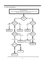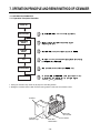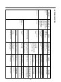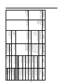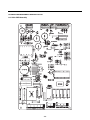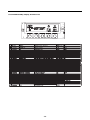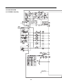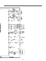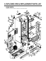
1
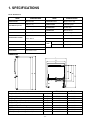
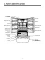
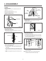
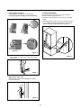
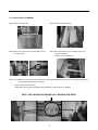
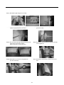
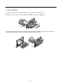
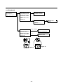
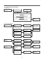
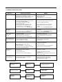
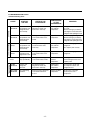
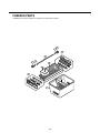
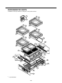
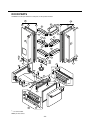
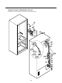
REFRIGERATOR
SERVICE MANUAL
CAUTION
BEFORE SERVICING THE PRODUCT,
READ THE SAFETY PRECAUTIONS IN THIS MANUAL.
MODELS: LFD21860ST
LFD21860SW
LFD25860ST
LFD25860TT
LFD25860SB
LFD25860SW
COLORS: WESTERN BLACK(SB)
TITANIUM(TT)
SUPER WHITE(SW)
STAINLESS(ST)
CONTENTS
SAFETY PRECAUTIONS ....................................................................................................................................................... 2
SPECIFICATIONS................................................................................................................................................................... 3
PARTS IDENTIFICATION ....................................................................................................................................................... 4
DISASSEMBLY.................................................................................................................................................................. 5-10
DOOR................................................................................................................................................................................ 5-6
DOOR ALIGNMENT..............................................................................................................................................................6
HOW TO REMOVE AND REINSTALL THE PULLOUT DRAWER.................................................................................... 7-9
ADJUSTMENT ................................................................................................................................................................. 10-11
COMPRESSOR.................................................................................................................................................................. 10
PTC-STARTER................................................................................................................................................................... 10
OLP (OVERLOAD PROTECTOR)...................................................................................................................................... 11
TO REMOVE THE COVER PTC .........................................................................................................................................11
CIRCUIT DIAGRAM.............................................................................................................................................................. 12
TROUBLESHOOTING..................................................................................................................................................... 13-18
COMPRESSOR AND ELECTRIC COMPONENTS ........................................................................................................... 13
PTC AND OLP.................................................................................................................................................................... 14
OTHER ELECTRICAL COMPONENTS ............................................................................................................................. 15
SERVICE DIAGNOSIS CHART.......................................................................................................................................... 16
REFRIGERATION CYCLE ............................................................................................................................................ 17-18
OPERATION PRINCIPLE AND REPAIR METHOD OF ICEMAKER ............................................................................. 19-22
DESCRIPTION OF FUNCTION AND CIRCUIT OF MICOM .......................................................................................... 23-40
EXPLODED VIEW AND REPLACEMENT PARTS LIST ................................................................................................... 41-
SAFETY PRECAUTIONS
Please read the following instructions before servicing your refrigerator.
1. Unplug the power before handling any elctrical componets.
2. Check the rated current, voltage, and capacity.
3. Take caution not to get water near any electrical components.
4. Use exact replacement parts.
5. Remove any objects from the top prior to tilting the product.
-2-
1. SPECIFICATIONS
21 cu. ft./25 cu. ft.
ITEMS
SPECIFICATIONS
DOOR DESIGN
ITEMS
SPECIFICATIONS
Side Rounded
VEGETABLE TRAY
Opaque Drawer Type
298 (21 cu. ft.)
COMPRESSOR
PTC Starting Type
320 (25 cu. ft.)
EVAPORATOR
Fin Tube Type
COOLING SYSTEM
Fan Cooling
CONDENSER
Wire Condenser
TEMPERATURE CONTROL
Micom Control
REFRIGERANT
R-134a (115 g)
Full Automatic
LUBRICATING OIL
ISO10 (280 ml)
Heater Defrost
DEFROSTING DEVICE
SHEATH HEATER
NET WEIGHT (pounds)
DEFROSTING SYSTEM
DOOR FINISH
PCM, VCM, Stainless
REFRIGERATOR
60 W (2 EA)
FREEZER
60 W (1 EA)
LAMP
HANDLE TYPE
Bar
INNER CASE
ABS Resin
INSULATION
Polyurethane Foam
DIMENSIONS
Description
Depth w/ Handles
Depth w/o Handles
Depth w/o Door
Depth (Total with Door Open)
Height to Top of Case
Height to Top of Door Hinge
Width
Width (door open 90 deg. w/o handle)
Width (door open 90 deg. w/ handle)
A
B
C
D
E
F
G
H
I
-3-
LFD21860**
30 in.
27 1/2 in.
23 5/8 in.
42 1/4 in.
68 3/8 in.
69 3/4 in.
35 3/4 in.
39 1/4 in.
44 1/4 in.
LFD25860**
34 1/4 in.
31 3/4 in.
27 7/8 in.
46 1 /2 in.
68 3/8 in.
69 3/4 in.
35 3/4 in.
39/1/4 in.
44 1/4 in.
2. PARTS IDENTIFICATION
Digital Sensor
Control
Dairy Bin
Refrigerator Light
Egg Box
Shelves
Modular Door Bin
Modular Door Bin
Bottle Holder
Optibin Crisper
Keeps fruits and
vegetable fresh
and crisp
Modular Door Bin
Glide'N'Serve
Customcube
Icemaker
Pullout Drawer
Ice Bin
Durabase
Tilt- Out
Door Basket
(Tilting-LFC25860** Only)
Divider
-4-
3. DISASSEMBLY
3-1 DOOR
● Refrigerator
door
1. Remove the top hinge cover and disconnect the wire
harness.
2. Remove the ground screw.
3. Rotate the lever hinge and lift off hinge.
4. Lift off the refrigerator door.
5. Replace in the reverse order.
Gasket
Bracket Clip
Door
Frame
Flat Tip
Screwdriver
Gasket
Bracket
Figure 3
HINGE COVER
3. Remove gasket
Pull gasket free from gasket channel on the three
remaining sides of door.
HINGE
Figure 1
● Door
gasket removal
1. Remove door frame cover
Starting at top of cover and working down, snap cover
out and away from door.
Figure 4
● Door
gasket replacement
1. Insert gasket bracket clips
1) Insert gasket bracket edge beneath door frame edge.
2) Turn upper gasket bracket spring so that both spring
ends are in the door channel.
3) Push in clip until you hear it snap securely into place.
Frame Cover
Handle
Gasket
Bracket Clip
Figure 2
Spring
2. Remove gasket bracket clips
There are two clips on each door. Start bracket removal
near one of the middle clips.
1) Pull gasket back to expose gasket bracket clip and
door frame.
2) Insert a flat tip screwdriver into seam between gasket
bracket and door frame and pry back until clips snaps
out.
3) Continue prying back along seam until all clips snap
out.
Door
Frame
Correct
Incorrect
Figure 5
4) Push in remaining two clips until you hear each snap
securely into place.
Note: Make sure that no part of gasket bracket edge
protrudes from beneath door frame edge.
-5-
2. Insert gasket into channel
1) Snap gasket assembly into the door bracket.
Inserting the gasket assembly into the bracket door
3-2 DOOR ALIGNMENT
If the space between your doors is uneven, follow the
instructions below to align the doors:
1. With one hand, lift the door you want to raise at middle
hinge.
2. With other hand, use pliers to insert snap ring as shown.
3. Insert additional snap rings until the doors are aligned.
(Three snap rings are provided with the product.)
Correct
Incorrect
Figure 6
Figure 9
2) Press gasket into channels on the three remaining
sides of door.
Figure 7
3. Replace door frame cover
Starting at top of cover and working down, snap the
cover back into door.
Figure 8
-6-
3-3 HOW TO REMOVE AND REINSTALL THE PULLOUT DRAWER
3-3-1 FOLLOW STEPS TO REMOVE
Step 1) Open the freezer door.
Step 2) Remove the lower basket.
Step 3) Remove the two screws from the guide rails (one
from each side).
Step 4) Lift the freezer door up to unhook it from the rail
support and remove.
Pull both rails to full extension.
Step 5) First: Remove the gear from the left side first by releasing the tab behind the gear, place a screwdriver between the
gear and the tab and pull up on the gear.
Second: Remove the center rail.
Third: Remove the gear from the right side by following the same steps for the left side.
NOTE: THIS TAB MUST BE PUSHED IN TO RELEASE THE GEAR.
-7-
3-3-2 FOLLOW STEPS TO REINSTALL
Step 1) Reinstall the right side gear into the clip.
Step 2) Insert the rail into the right side gear. Gears do not
need to be perpendicular to each other.
Step 3) Insert the rail into the left side gear, and insert the
gear into the clip.
Step 4) The rail system will align itself by pushing the rails
all the way into the freezer section.
Pull the rails back out to full extension.
Step 5) Reinstall the freezer door by inserting the rail tabs
into the guide rail.
Step 6) Reinstall the two screws into the guide rails
(one from each side).
Step 7) Reinstall the lower basket, and close the freezer
door.
-8-
3-3-3 PULL OUT DRAWER
To separate the drawer, push the front left and right hooks in
direction to pull up and remove.
Then gently lift the gear part of rear left and right side of the drawer and pull it out in
direction.
1
3
2
To install, reposition the gear part of rear left and right side of the drawer after pulling out both rails as much as possible,
and gently push down both left and right side while checking the hook on the front part.
Hook
-9-
4. ADJUSTMENT
4-2-3 PTC-Applied circuit diagram
method for the motor
4-1 COMPRESSOR
● Starting
4-1-1 Role
The compressor intakes low temperature and low pressure
gas from the evaporator of the refrigerator and compresses
this gas to high-temperature and high-pressure gas. It then
delivers the gas to the condenser.
OVERLOAD PROTECTOR
N
4-1-2 Composition
The compressor includes overload protection. The PTC
starter and OLP (overload protector) are attached to the
outside of the compressor. Since the compressor is
manufactured to tolerances of 1 micron and is hermetically
sealed in a dust and moisture-free environment, use
extreme caution when repairing it.
PTC
2
5
L1
4-1-3 Note for usage
(1) Be careful not to allow over-voltage and over-current.
(2) If compressor is dropped or handled carelessly, poor
operation and noise may result.
(3) Use proper electric components appropriate to the
particular compressor in your product.
(4) Keep compressor dry.
If the compressor gets wet (in the rain or a damp
environment) and rust forms in the pin of the Hermetic
Terminal, poor operation and contact may result.
If the hermetic connector rusts out or fails, refrigerant
and oil will be expelled into the contact area, probably
resulting in smoke and fire.
(5) When replacing the compressor, be careful that dust,
humidity, and soldering flux don’t contaminate the inside
of the compressor. Contamination in the cylinder may
cause noise, improper operation or even cause it to
lock up.
4-2 PTC-STARTER
4-2-1 Composition of PTC-Starter
(1) PTC (Positive Temperature Coefficient) is a no-contact
semiconductor starting device which uses ceramic
material consisting of BaTiO3.
(2) The higher the temperature is, the higher the resistance
value. These features are used as a starting device for
the motor.
4-2-2 Role of PTC-Starter
(1) The PTC is attached to the sealed compressor and is
used for starting the motor.
(2) The compressor is a single-phase induction motor.
Durign the starting operation, the PTC allows current
flow to both the start winding and main winding.
C
S
3
6
PTC STARTER
COMPRESSOR
MOTOR
M
M
S
SEALED
TERMINAL
Resistance Starter Capacitor Running
Figure 17
4-2-4 Motor restarting and PTC cooling
(1) It requires approximately 5 minutes for the pressure to
equalize before the compressor can restart.
(2) The PTC device generates heat during operation.
Therefore, it must be allowed to cool before the
compressor can restart.
4-2-5 Relation of PTC-Starter and OLP
(1) If the compressor attempts to restart before the PTC
device is cooled, the PTC device will allow current to
flow only to the main winding.
(2) The OLP will open because of the overcurrent
condition. This same process will continue (3 to 5
times) when the compressor attempts to restart until
the PTC device has cooled. The correct OLP must be
properly attached to prevent damage to the
compressor.
Parts may appear physically identical but could
have different electrical ratings. Replace parts by
part number and model number. Using an incorrect
part could result in damage to the product, fire,
injury, or possibly death.
4-2-6 Note for using the PTC-Starter
(1) Be careful not to allow over-voltage and over-current.
(2) Do not drop or handle carelessly.
(3) Keep away from any liquid.
If liquid such as oil or water enters the PTC,
PTC materials may fail due to breakdown of their
insulating capabilities.
(4) If the exterior of the PTC is damaged, the resistance
value may be altered. This can cause damage to the
compressor and result in a no-start or hard-to-start
condition.
(5) Always use the PTC designed for the compressor and
make sure it is properly attached to the compressor.
Parts may appear physically identical but could have
different electrical ratings. Replace parts by part
number and model number. Using an incorrect part
could result in damage to the product, fire, injury, or
possibly death.
- 10 -
4-3 OLP (OVERLOAD PROTECTOR)
4-4 TO REMOVE THE COVER PTC
4-3-1 Definition of OLP
(1) OLP (OVERLOAD PROTECTOR) is attached to the
compressor and protects the motor by opening the
circuit to the motor if the temperature rises and
activating the bimetal spring in the OLP.
(2) When high current flows to the compressor motor, the
bimetal works by heating the heater inside the OLP, and
the OLP protects the motor by cutting off the current
flowing to the compressor motor.
4-3-2 Role of the OLP
(1) The OLP is attached to the sealed compressor used for
the refrigerator. It prevents the motor coil from being
started in the compressor.
(2) For normal operation of the OLP, do not turn the
adjustment screw of the OLP in any way.
(2) Disconnect the two connectors on the top of the
compressor..
(OVERLOAD PROTECTOR cross section)
12345678
330 FBYY
Electrical
characteristics
part number
-S1 BOX98
Customer part
number
Lot code/
date code
Physical
termination
part number
(1) Remove the back cover of the mechanical area..
Part
No.
Name
(3) Loosen two screws on compressor base.
Base, phenolic
(UL 94 V-0 rated)
Movable arm support, plated steel
Stationary contact support,
plated steel
Heater support, plated steel
Heater, resistance alloy
Disc, thermostatic alloy
Movable arm, spring temper
copper alloy
Contact, movable, silver on copper
Contact, stationary, silver on copper
Slug, plated steel
Cover, polyester
(UL 94 V -0 rated)
Pin connector, plated copper alloy
(To engage 2.33/2.66 mm dia. pin)
1
2
3
Figure 18
(4) Use a flat screwdriver to pry off the cover.
(5) Assembly is the reverse order of disassembly.
- 11 -
5. CIRCUIT DIAGRAM
- 12 -
6. TROUBLESHOOTING
6-1 COMPRESSOR AND ELECTRIC COMPONENTS
1
Power source.
YES
Remove PTC-Starter
from compressor and
measure voltage
between terminal C of
compressor and
terminal 5 or 6 of PTC.
(Rated voltage
±10%)?
No voltage.
OLP disconnected?
2
YES
Replace OLP.
NO
5
Check connection
condition.
Reconnect.
Applied voltage isn't
in acceptable range.
(115V ±10%)
Advise customer that
power supply needs to be
checked by an electrician.
The range of resistance is between 1~50½ (ok)
Check
resistance of
motor
compressor.
Check resistance
between M-C, S-C and
M-S in motor
compressor.
3
Check
resistance of
PTC-Starter.
Check resistance of
two terminals in
PTC-Starter.
Refer to page 12.
4
Check OLP.
Check resistance of two
terminals in OLP.
Refer to page 12.
5
Check
starting state.
Check the power supply
under load.
(Compressor attempting
to re-start after being off
for 5 minutes).
2
5
Open or short
Replace
compressor.
Supply
voltage rating
with ±10%.
YES
3
Did
compressor
start?
4
YES
NO
NO
- 13 -
3
5
Compressor
is OK
Replace the
compressor
1
6-2 PTC AND OLP
Separate PTC-Starter
from compressor and
measure resistance
between No. 5 and 6
of PTC-Starter with a
tester.
(Figure 19)
Observation value is
115V/60Hz : 6.8Ω±30%
The resistance value
is 0Ω (short) or
∞ (open).
Separate OLP from
compressor and check
resistance value
between two terminals
of OLP with a tester.
(Figure 20)
Shows continuity
Open
Check another
electric component.
Replace OLP.
5
6
Normal operation of
compressor is
impossible or poor.
Figure 19
- 14 -
Figure 20
Replace PTCStarter.
6-3 OTHER ELECTRICAL COMPONENTS
▼ Not cooling at all
Compressor
doesn't run.
Check for open short or
incorrect resistance readings
in the following components
Cause
a. Starting devices
Short, open, or broken.
b. OLP
Poor contact
or shorted.
c. Compressor coil
Coil open or shorted.
d. Wiring harness
Poor contact
or shorted.
Replace
indicated component.
▼ Poor cooling performance
Compressor runs
poorly.
Fan motor
doesn't run.
Check starting
voltage.
Low voltage.
Advise customer that
the power supply
needs to be checked
by an electrician.
Check voltage at
starting devices.
Poor or broken or
open contact.
Replace
indicated component.
Check current flowing
in sub-coil of
compressor.
Shorted.
Check rating of OLP.
Lack of capacity.
Check wiring circuit.
Wire is open or
shorted.
Coil is shorted
or open.
Check fan motor.
Heavy frost buildup on
evaproator.
Replace
indicated component.
Check current flow in
the following
components:
sensor
melting fuse
Check current flow in
the defrost heater.
- 15 -
Open.
Replace
indicated component.
Open.
Replace
defrost heater.
6-4 SERVICE DIAGNOSIS CHART
COMPLAINT
POINTS TO BE CHECKED
REMEDY
No Cooling.
• Is the power cord unplugged from the outlet?
• Check if the power switch is set to OFF.
• Check if the fuse of the power switch is shorted.
• Measure the voltage of the power outlet.
• Plug into the outlet.
• Set the switch to ON.
• Replace the fuse.
• If the voltage is low, correct the wiring.
Cools poorly.
• Check if the unit is placed too close to the wall.
• Check if the unit is placed too close to the stove,
gas cooker, or in direct sunlight.
• Is the ambient temperature too high or
the room door closed?
• Check if food put in the refrigerator is hot.
• Did you open the door of the unit too often
or check if the door is sealed properly?
• Check if the Control is set to warm position.
• Place the unit about 4 inches (10 cm) from the wall.
• Place the unit away from these heat sources.
• Is food placed in the cooling air outlet?
• Check if the control is set to colder position.
• Is the ambient temperature below 5°C?
• Place foods in the high-temperature section.
(front part)
• Set the control to recommended position.
• Set the control to warm position.
Condensation or ice
forms inside
the unit.
• Is liquid food sealed?
• Check if food put in the refrigerator is hot.
• Did you open the door of the unit too
often or check if the door is sealed properly?
• Seal liquid foods with wrap.
• Put in foods after they have cooled down.
• Don't open the door too often and close
it firmly.
Condensation forms
in the Exterior Case.
• Check if the ambient temperature and humidity
of the surrounding air are high.
• Is there a gap in the door gasket?
• Wipe moisture with a dry cloth. It will disappear
in low temperature and humidity.
• Fill up the gap.
There is abnormal
noise.
• Is the unit positioned in a firm and even place?
• Adjust the leveling screw, and position the
refrigerator in a firm place.
• Remove the objects.
Food in the
Refrigerator
is frozen.
• Are any unnecessary objects placed
behind of the unit?
• Check if the drip tray is not firmly attached.
• Check if the cover of the compressor enclosure
in the lower front side is taken out.
Door does not
close well.
• Check if the door gasket is dirty with
an item like juice.
• Is the refrigerator level?
●
• Put in foods after they have cooled down.
• Don't open the door too often and close
it firmly.
• Set the control to recommended position.
• Fix the drip tray firmly in the original position.
• Place the cover in its original position.
• Clean the door gasket.
• Is there too much food in the refrigerator?
Ice and foods
smell unpleasant.
• Lower the ambient temperature.
• Check if the inside of the unit is dirty.
• Are foods with a strong odor unwrapped?
• The unit smells of plastic.
• Position in a firm place and level the
leveling screw.
• Make sure food stored in shelves does not prevent
the door from closing.
• Clean the inside of the unit.
• Wrap foods that have a strong odor.
• New products smell of plastic, but this
will go away after 1-2 weeks.
Other possible problems:
Check if frost forms in
the freezer.
Not
defrosting
Check components of
the defrosting circuit.
Check the
refrigeration system.
The system
is faulty.
Perform sealed
system repair.
Check the
thermistor.
The operation of
the thermistor is
incorrect.
- 16 -
Replace the
thermistor.
6-5 REFRIGERATION CYCLE
▼ Troubleshooting Chart
CAUSE
STATE OF
THE UNIT
STATE OF THE
EVAPORATOR
TEMPERATURE
OF THE
COMPRESSOR
REMARKS
Freezer
compartment and
refrigerator don't
cool normally.
Low flowing sound of
refrigerant is heard and
frost forms in inlet only.
A little higher
than ambient
temperature.
• Refrigerant level is low due
• to a leak.
• Normal cooling is possible by
• restoring the normal amount of
• refrigerant and repairing the leak.
COMPLETE
LEAKAGE
Freezer
compartment and
refrigerator don't
cool normally.
Flowing sound of refrigerant
is not heard and frost isn't
formed.
Equal to ambient
temperature.
• No discharging of refrigerant.
• Normal cooling is possible by
• restoring the normal amount of
• refrigerant and repairing the leak.
PARTIAL
CLOG
Freezer
compartment and
refrigerator don't
cool normally.
Flowing sound of refrigerant
is heard and frost forms
in inlet only.
A little higher
than ambient
temperature.
• Normal discharging of the
• refrigerant.
• The capillary tube is faulty.
WHOLE
CLOG
Freezer
compartment and
refrigerator don't cool.
Flowing sound of refrigerant
is not heard and frost isn't
formed.
Equal to ambient
temperature.
• Normal discharging of the
• refrigerant.
MOISTURE
CLOG
Cooling operation
stops periodically.
Flowing sound of refrigerant
is not heard and frost melts.
Lower than
ambient
temperature.
• Cooling operation restarts
• when heating the inlet of the
• capillary tube.
COMPRESSION
Freezer and
refrigerator
don't cool.
Low flowing sound of
refrigerant is heard and
frost forms in inlet only.
A little higher
than ambient
temperature.
• Low pressure at high side
• of compressor due to low
• refrigerant level.
NO COMPRESSION
No compressing
operation.
Flowing sound of refrigerant
is not heard and there is
no frost.
Equal to ambient
temperature.
• No pressure in the high
• pressure part of the
• compressor.
LEAKAGE
PARTIAL
LEAKAGE
CLOGGED BY DUST
DEFECTIVE
COMPRESSION
- 17 -
6-5-1 SEALED SYSTEM DIAGNOSIS
Not Cooling Complaint
All components operating, No airflow problems, Not frosted up as a defrost problem
problem has been isolated to sealed system area
Frost
Pattern?
Partial
None
Equalization
Test
Equalization
Test
Very Fast
Very Slow
Very Slow
Very Fast
Fast
Inefficient
Compressor
Partial
Restriction
Complete
Restriction
Condenser
Temperature
Cap Tube
Sound
Hotter than Normal
Faint
Room Temperature
None to Weak
Air/Low Side
Leak
Loss of Change
Compressor Not
Pumping
Trace of Oil
Yes
No
Leak
Undercharge
(The equalization test is trying to restart a compressor using a start kit after it has been operating.)
- 18 -
7. OPERATION PRINCIPLE AND REPAIR METHOD OF ICEMAKER
7-1 OPERATION PRINCIPLE
7-1-1 Operation Principle of Icemaker
Power On
¥ Adjusts EJECTOR to Start Position with power on.
Start Position
Icemaking
Mode
¥ Waits until water becomes cold after starting the
icemaking operation.
Harvest
Mode
¥ Runs MOTOR to drop ice from the tray into the ICE BIN.
¥ Performs Icemaking Mode after supplying water by operating
the SOLENOID in ICE VALVE.
Fill
¥ With the detect lever, checks if the ICE BIN is full.
Park Position
¥ To operate LINE and SERVICE, press and hold the Fill Key
for 3 seconds. The icemaker will run through 3 stages:
Harvest
Fill
Icemaking.
Test Mode
1. Turning the Icemaker stop switch off (O) stops the icemaking function.
2. Setting the Icemaker switch to OFF and then turning it back on will reset the icemaker control.
Icemaker
Automatic
Shut off Arm
Cube Size
Indicator Light
Power Switch
Cube Size
Select Button
- 19 -
7-2 ICE MAKER FUNCTIONS
7-2-1 Start Position
1. After POWER OFF or power outage, check the EJECTOR's position with MICOM initialization to restart.
2. How to check if it is in place:
- Check HIGH/LOW signals from HALL SENSOR in MICOM PIN.
3. Control method to check if it is in place:
(1) EJECTOR is in place,
- It is an initialized control, so the mode can be changed to ice making control.
(2) EJECTOR isn't in place:
A. If EJECTOR is back in place within 2 minutes with the motor on, it is being initialized. If not, go to step B.
B. If EJECTOR is back in place within 18 minutes after the heater turns from ON to OFF, it is being initialized. If not, it is
not functioning. Repeat step B with heater and motor off.
7-2-2 Ice Making Mode
1. Icemaking refers to the freezing of supplied water in the ice trays. Complete freezing is assured by measuring the
temperature of the Tray with icemaking SENSOR.
2. Icemaking starts after completion of the water fill operation.
3. The icemaking function is completed when the sensor reaches -7°C, 60 to 240 minutes after starting.
4. If the temperature sensor is defective, the icemaking function will be completed in 4 hours.
NOTE : After icemaker power is ON, the icemaker heater will be on for test for 9 sec.
7-2-3 Harvest Mode
1. Harvest (Ice removing) refers to the operation of dropping ices into the ice bin from the tray when icemaking has
completed.
2. Harvest mode:
(1) The Heater is ON for 30 seconds, then the motor starts.
(2) Harvest mode is completed if it reaches start position again while Heater & Motor are on at the same time.
A. ice bin is full : The EJECTOR stops (heater off).
B. ice bin is not full : The EJECTOR rotates twice to open for ice.
NOTE : If the EJECTOR does not rotate once within 5 minutes in status (2), separate heater control mode starts
operating to prevent the EJECTOR from being constrained. (It is recommended that the user open for ice to
return to normal mode.)
- 20 -
7-2-4 Fill/Park Position
1. Once a normal harvest mode has been completed, the water solenoid will be activated.
2. The amount of water is adjusted by pressing the fill key repeatedly. This changes the time allowed for fill as illustrated in
the table below.
Water supply amount table
STAGE
TIME TO SUPPLY
1
6 sec.
INDICATIONS
REMARKS
The water amount will vary depending
2
on the water control switch setting, as
7 sec.
well as the water pressure of the
connected water line.
3
8 sec.
- 21 -
7-2-5 Function TEST
1. This is a compulsory operation for test, service, cleaning, etc. It is operated by pressing and holding the fill key for 3 seconds.
2. The test works only in the icemaking mode. It cannot be entered from the harvest or fill mode. (If there is an ERROR, it
can only be checked in the test mode.)
3. Caution! If the test is performed before water in the icemaker is frozen, the ejector will pass through the water. When the
fill mode begins (stage 4), unless the water supply has been shut off, added water will overflow into the ice bin. If the
control doesn’t operate normally in the test mode, check and repair as needed.
4. After water is supplied, the normal cycle is followed: icemaking → harvest → fill → park position.
5. Five seconds after stage 5 is completed, the icemaker returns to MICOM control. The time needed to supply water resets
to the pre-test setting.
7-3 DEFECT DIAGNOSIS FUNCTION
7-3-1 ERROR CODE on water supply control panel at Ice Maker
- 22 -
8. DESCRIPTION OF FUNCTION & CIRCUIT OF MICOM
8-1 FUNCTION
8-1-1 Function
1. When the appliance is plugged in, it defaults to 37°F for the refrigerator and 0°F for the freezer.
You can adjust the refrigerator and the freezer control temperature by pressing the ADJUST button.
2. When the power is initially applied or restored after a power failure, it is automatically set to 37 & 0.
8-1-2 How to Change the Temperature Mode to °F/°C
1. The display temperature mode can be changed from °F to °C or °C to °F by pressing and holding the FRZ TEMP and the
COLDER key of REF TEMP keys at the same time for over five seconds
2. The initial setting is °F. Whenever the mode is changed, the LED lights are changed.
8-1-3 Control of freezer fan motor
1. Freezer fan motor runs at either regular or high speed.(2,400 or 2,700 rpm.)
2. High RPM is used when electricity is first on, for ICE PLUS, and when refrigerator is overloaded.
Standard RPM is used for normal usage.
3. The fan motor is stopped when any door is opened.
8-1-4 ICE PLUS
1. The purpose of this function is to intensify the cooling speed of freezer and to increase the amount of ice.
2. Whenever selection switch is pressed, selection/release, the icon will turn ON or OFF.
3. If there is a power outage and the refrigerator is powered on again, ICE PLUS will be canceled.
4.To activate this function you need to press the ICE PLUS key and the icon will turn ON. This function will remain activated
for 24 hours. The first three hours the compressor and freezer fan will be ON. The next 21 hours the freezer will be
controlled at the lowest temperature. After 24 hours or if the iICE PLUS key is pressed again, the freezer will return to its
previous temperature.
5. During the first 3 hours:
(1) Compressor and freezer fan (HIGH RPM) run continuously.
(2) If a defrost cycle begins during the first 90 minutes of ICE PLUS, the ICE PLUS cycle will complete its cycle after
defrosting has ended. If the defrost cycle begins when iICE PLUS has run for more than 90 minutes, ICE PLUS will run
for two hours after the defrost is completed.
(3) If ICE PLUS is pressed during defrost, ICE PLUS icon is on this function will start seven minutes after defrost is
completed and it shall operate for three hours.
(4) If ICE PLUS is selected within seven minutes after compressor has stopped, the compressor (compressor delays
seven minutes) will start after the balance of the delay time.
(5) The fan motor in the freezer compartment rotates at high speed during ICE PLUS.
6. For the rest of 21 hours, the freezer will be controlled at the lowest temperature.
8-1-5. REFRIGERATOR LAMP AUTO OFF
1. To protect the risk of lamp heat, when the refrigerator door is opened for 7 minutes, the refrigerator lamp will be turned off
automatically.
- 23 -
8-1-6 Alarm for Open Door
1. This feature sounds a buzzer when the freezer or refrigerator door is not closed within 1 minute after it is opened.
2. One minute after the door is opened, the buzzer sounds three times each for 1/2 second. These tones repeat every 30
seconds.
3. The alarm is cancelled when the freezer or the refrigerator is closed while the buzzer sounds.
Freezer Door Closed
or Refrigerator
Door
Open
Closed
Open
Closed
3 Times
3 Times
3 Times
3 Times
Buzzer
Within 1 min.
1 min.
30 sec
30 sec
30 sec
8-1-7 Buzzer Sound
When the button on the front display is pushed, a Ding~ Dong~ sound is produced.
8-1-8 Defrosting (removing frost)
1. Defrosting starts each time the compressor running time reaches 7 hours.
2. For initial power on or for restoring power, defrosting starts when the compressor running time reaches 4 hours.
3. Defrosting stops if the sensor temperature reaches 8°C or more. If the sensor doesn’t reach 8°C in 2 hours, the defrost
mode is malfunctioning.
4. Defrosting won’t function if its sensor is defective (wires are cut or short circuited)
- 24 -
8-1-9 Electrical Parts Are Turned On Sequentially
Electrical parts such as compressor, defrosting heater, freezer fan, etc. are turned on in the following order to prevent noise
and parts damage. Several parts are started at the same time at initial power on and are turned off together when test is
completed.
OPERATING
Initial power on
Temperature of defrosting
sensor is 45°C or more
(when unit is newly
purchased or when moved)
Temperature of defrosting
sensor is lower than 45°C
(during power outages or
for service)
Reset to normal operation
from test mode
ORDERS
Power
ON
in 0.5 sec.
Power
ON
in 0.5 sec.
Total load
OFF
Compressor
ON
in 0.5 sec.
Defrosting
heater ON
Compressor
ON
in 7 min.
- 25 -
in 0.5 sec.
in 0.5 sec.
Compressor
ON
Freezer fan
ON
in 10 sec.
Defrost heater
OFF
Freezer fan
ON
in 0.5 sec.
Freezer fan
ON
8-1-10 Defect Diagnosis Function
1. Automatic diagnosis makes servicing the refrigerator easy.
2. When a defect occurs, the buttons will not operate; but the tones, such as ding, will sound.
3. When the defect CODE removes the sign, it returns to normal operation (RESET).
4. The defect CODE shows on the refrigerator and freezer display.
ERROR CODE on display panel
Note 1) Room temperature sensor is not indicated on the failure indicating part but indicated in checking
display. (When pressing for more than the warmer key of refrigerator temp and the warmer kye of
freezer temp for more than 1 second).
✽ LED check function: If press and hold the warmer key of refrigerator temp and the warmer key of freezer
temp for a second, all display LED graphics on. When you release the buttons, the LED graphics displays the
previous status.
- 26 -
8-1-11 TEST Mode
1. The test mode allows checking the PCB and the function of the product as well as finding out the defective part in case of
an error.
2. The test mode is operated by pressing two buttons on the display panel.
3. While in the test mode, the function control button is not recognized, but the recognition tone (beep~) sounds.
4. After exiting the test mode, be sure to reset by unplugging and then plugging in the appliance.
5. If an error, such as a sensor failure, is detected while in the test mode, the test mode is cleared and the error code is
displayed.
6. While an error code is displayed, the test mode will not be activated.
* Freezer Fan Variable RPM Check:
To check the variable rpm, press and hold the WARMER keys of both the REF TEMP and FRX TEMP. The fan speed will
change (low to high or high to low) for 30 seconds before reverting to its original setting.
* Demonstration (Display) MODE:
1. To enter this mode, raise either the Refrigerator or Freezer temperature to its highest setting. Then, press and hold
WARMER Key for 5 seconds.
2. The LED panels will display OFF, to indicate that the compressor, circulating fan, damper, and defrost heater are not
operating.
3. The open door alarm and the lamp auto-off feature will work normally and can be demonstrated.
4. To reset to normal operation, press and hold either WARMER key for about 5 seconds.
- 27 -
8-2 PCB FUNCTION
8-2-1 Power Circuit
The secondary part of the TRANSFORMER is composed of the power supply for the display, the BLDC FAN Motor drive
(15.5 V), the relay drive (12 Vdc) and the MICOM and IC (5 Vdc).
The voltage for each part is as follows:
PART
VA 1
CE 3
CE 4
CE 5
VOLTAGE
115 Vac
12 Vdc
15.5 Vdc
5V
VA1 is a part for preventing over voltage and noise. When 385V or higher power is applied, the inside elements are shortcircuited and broken, resulting in blowout of the fuse in order to protect the elements of the secondary part of the
TRANSFORMER.
- 28 -
8-2-2 Oscillation Circuit
This circuit generates the base clock for calculating time and the synchro clock for transmitting data from and to the inside
logic elements of the IC1 (MICOM). Be sure to use specified replacement parts, since calculating time by the IC1 may be
changed. If changed, the OSC1 SPEC will not work.
8-2-3 Reset Circuit
The RESET circuit allows all the functions to start at the initial conditions by initializing various parts, including the RAM
inside the MICOM (IC1) when the power is initially supplied or the power supply to the MICOM is restored after a
momentary power failure. For the initial 10ms of power supply, LOW voltage is applied to the MICOM RESET terminal.
During a normal operation, 5V is applied to the RESET terminal. (If a malfunction occurs in the RESET IC, the MICOM will
not operate.)
- 29 -
8-2-4 Load / Buzzer Drive & Open Door Detection Circuit
1. Load Drive Condition Check
LOAD TYPE
COMP
Measurement Location (IC6)
NO.16
DEFROSTING
HEATER
NO.11
LAMP-F
NO.12
LAMP-R
WATER
VALVE/VALVE2
FRENCH
DOOR
HEATER
NO.13
NO.14
NO.15
ON
1V or below
OFF
12V
Condition
2. Fan motor driving circuit (freezer compartment fan)
1. This circuit makes standby power 0 by cutting off power supplied to ISs inside of the fan motor in the fan motor OFF.
2. This is a circuit to perform a temporary change of speed for the fan motor and applies DC voltage up to 7.5V ~ 16V to motor.
3. This circuit prevents over-driving the fan motor by cutting off power applied to the fan motor in the lock of fan motor by
sensing the operation RPM of the fan motor.
a part
b part
c part
MOTOR OFF
2V or less
0V
5V
MOTOR ON
13V~15V
0V
2V~3V
- 30 -
2. Open Door Detection Circuit Check
Measurement
Location
Freezer/
Refrigerator Door
(PIN NO.30 & PIN NO.27)
Closed
5V
Open
0V
- 31 -
8-2-5 Temperature Sensor Circuit
The upper circuit reads refrigerator temperature, freezer temperature, and defrost sensor temperature for defrosting and the
indoor temperature for compensating for the surrounding temperature into MICOM.
Opening or short state of each temperature sensor are as follows:
SENSOR
CHECK POINT
Freezer sensor
POINT A Voltage
Refrigerator sensor
POINT B Voltage
Defrosting sensor
POINT C Voltage
Room Temperature sensor
POINT D Voltage
NORMAL (-30°C ~ 50°C)
0.5 V ~ 4.5 V
8-2-6 Refrigeration Compartment Stepping Motor Damper Circuit
* The circuit shown below is the damper circuit to regulate the refrigerator temperature.
- 32 -
SHORT-CIRCUITED
0V
OPEN
5V
8-3 RESISTANCE SPECIFICATION OF SENSOR
TEMPERATURE
RESISTANCE OF FREEZER
SENSOR
RESISTANCE OF REFRIGERATOR &
DEFROST SENSOR & ROOM SENSOR
- 20 ˚C
22.3 KΩ
77 KΩ
- 15 ˚C
16.9 KΩ
60 KΩ
- 10 ˚C
13.0 KΩ
47.3 KΩ
- 5 ˚C
10.1 KΩ
38.4 KΩ
0 ˚C
7.8 KΩ
30 KΩ
+ 5 ˚C
6.2 KΩ
24.1 KΩ
+ 10 ˚C
4.9 KΩ
19.5 KΩ
+ 15 ˚C
3.9 KΩ
15.9 KΩ
+ 20 ˚C
3.1 KΩ
13 KΩ
+ 25 ˚C
2.5 KΩ
11 KΩ
+ 30 ˚C
2.0 KΩ
8.9 KΩ
+ 40 ˚C
1.4 KΩ
6.2 KΩ
+ 50 ˚C
0.8 KΩ
4.3 KΩ
• The resistance of the SENSOR has a ±5% tolerance.
• Measure the resistance of the SENSOR after leaving it for over 3 minutes in the measuring temperature.
This delay is necessary due to sensor response speed.
• Measure the F-SENSOR, SUPER FROST SENSOR, R1, R2-SENSOR after disconnect CON5 of PWB ASSY, MAIN.
- 33 -
8-4 TROUBLESHOOTING
1. The whole DISPLAY
LED/SEVEN SEGMENT
DISPLAY is off.
2. DISPLAY LED/
SEVEN SEGMENT
DISPLAY operates
abnormally
INDICATED BY
Power source
is poor.
No cooling.
PROBLEM
Cooling is poor.
Freezer
temperature is
incorrect
CHECK
1. FREEZER/
REFRIGERATOR.
2. If lamp is dim.
3. The connection of
the main PWB
connector.
1. If the compressor
operates.
2. If refrigerant is leaking.
.
1. If fan motor
operates.
2. If defrosting
is normal.
3. If sensor
is normal.
4. Gasket seal incorrect.
CHECKING METHOD
Check if freezer or
refrigerator door is open
and check display.
Check visually.
Check connection of
connector.
Use Test Mode1
(forced cooling).
If less than 7 minutes pass
after compressor shuts off,
don’t press the key and
wait.
Measure the amount of frost
sticking on evaporator
and the surface temperature
of the condenser pipe.
Use Test Mode 1
(forced cooling).
Check the amount of frost
sticking on the evaporator .
Check the resistance
of the refrigerator
sensor.
Check the seal when
the door is closed.
Use boosting transformer.
Reconnect connector.
Check outlet voltage.
SOLUTION
Power source is poor.
Replace transformer.
CAUSE
Applied voltage error.
connector connection
is poor.
Transformer fuse is open.
Replace OLP, PTC.
Replace main PWB.
Replace compressor.
Compressor locked or
blocked.
OLP, PTC, or
compressor are failed.
Connection wire is defective.
Fan motor is defective.
Refer to 8-2-4. 2 and check
Replace the fan motor.
Check the connection of the
black wire of the main PWB
connector (CON2).
Replace the leaking part and
replace any lost refrigerant.
Connection wire is defective.
Refrigerant leakage.
Defrosting is poor.
Replace door liner.
See DEFROSTING
is poor, page 34.
Replace sensor.
Sensor resistance is
incorrect.
Door liner damaged.
- 34 -
PROBLEM
COOLING is defective.
DEFROSTING is
defective.
INDICATED BY
If refrigerator
temperature
is too low.
NO defrosting.
CHECK
1. If frezzer temperature
CAUSE
SOLUTION
Make sure the
CHECKING METHOD
Check is frezzer
door is attached.
Replace fan motor.
temperature is too low.
FAN motor is defective.
Remove impurities.
is normal.
Make sure that the amount
is blocked.
Passage of cool air
2. If amount of cool air from
sufficient by touching the
and speed of cool air are
Heater disconnection.
Door liner damaged.
Replace heater.
below.
Replace door liner.
See defrosting is poor,
Temperature fuse
is blown.
Connection is poor.
Door does not close
properly.
Connection is poor.
Defrost sensor is defective.
Heater relay is poor.
Drain pipe is blocked.
Replace temperature
fuse.
Check evaporator
connection and wire of main
PWB connector.
Replace defrost sensor.
Replace RY2 of main PWB.
Remove ice and impurities.
Check heater plate
resistance.
Reassemble the
defrost sensor.
Reassemble door.
Replace gasket.
Evaporator frozen.
fan motor is
check supplied on the
sufficient.
3. Door gasket contact.
refrigerator.
Check door seal when
door is closed.
USE TEST MODE3
Check drain pipe.
1. If heater emits heat.
2. If drain pipe is
blocked.
(forced defrosting).
3. If ice remains after
defrosting.
Make sure that defrost
sensor is connected.
Make sure that frezzer and
refrigerator doors are closed.
- 35 -
8-5 MAIN PWB ASSEMBLY AND PARTS LIST
8-5-1 Main PWB Assembly
- 36 -
8-5-2 Replacement Parts List
- 37 -
8-5-3 PWB Assembly, Display, And Parts List
- 38 -
8-6 PWB DIAGRAM
8-6-1 PWB Main Assembly
- 39 -
- 40 -
9. EXPLODED VIEW & REPLACEMENT PARTS LIST
CASE PARTS
CAUTION: Use the part number to order part, not the position number.
S03
S01
607A
207B
626A
402A
103B
624D
B01
271C
271B
S01
S03
103A
624C
410A
207A
S02
409D
624A
B01
406D
501F
402A
271B
271A
503D
S02
282F
410G
S11
S10
S08
610A
500A
409B
120B
145B
411A
145A
S12
313A
S13
406A
158A
S18
S11
262B
S14
301A
406B
B02
400A
610A
262H
B02
S14
318A
316A
316B
317A
S18
283B
249C
105A
249D
328A
314A
408A
106A
304A
300A
B03
409B
303B
405F
303C
283B
404A
405C
323B
405B
S20
329A
B03
420A
158B
106A
312A
329C
327A 309B
405A
S19
315B
319A
S15
319C
315C
S16
135D
310B
315A
332A
103C
315B
315C
135C
S17
B04
- 41 -
FREEZER PARTS
CAUTION: Use the part number to order part, not the position number.
250C
250D
145C
250A
250D
250C
136B
131A
145G
237C
136A
- 42 -
REFRIGERATOR PARTS
CAUTION: Use the part number to order part, not the position number.
147C
141B
141A
147B
147A
141B
141A
141C
141B
141A
141C
141B
141A
141C
146A
161E
*
141D
141C
161A
*
167B
154A
161D
*
160B
151C
161C
161F
*
151A
*
248A
155J
146B
161A
*
248H
145E
162B
145D
160B
160C
162A
* : only LFD21860**
- 43 -
DOOR PARTS
CAUTION: Use the part number to order part, not the position number.
230B
230A
241A
231B
233B
241B
233C
233D
231A
233A
241C
212G
234A
234B
241C
237A
237A
241C
*
244E
*
244E
241C
241C
▲
262C
▲
262C
312C
243A
243A
S26
243B
243B
312B
S25
S25
249A
615A
281C
249G
249E
250B
281F
281D
S34
205C
281F
281E
203A
200A
201A
250A
S34
205A
*
*
212D
205B
250B
249B
249F
249H
* : on some models
▲ Only for the service
- 44 -
WATER AND ICEMAKER PARTS
CAUTION: Use the part number to order part, not the position number.
S13
602A
600A
617A
616J 625A
616D
623B
S31
616C
616H
S31
616F
623B
616H
616E
603A
627A
S31
S30
616F
623A
S31
S31
627B
S31
619A
S32
603B
- 45 -
DISPENSER PARTS
CAUTION: Use the part number to order part, not the position number.
295A
S27
279A
616A
290A
279B
291A
293A
403A
292A
294A
279C
- 46 -
P/No. 3828JD8990F
APR., 2006 Printed in Korea