1
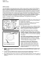
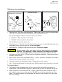
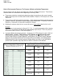
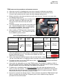
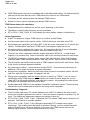
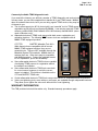
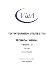
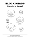
Page 1 of 11 Technical Service Bulletin SUBJECT: GENERAL SERVICE INFORMATION FOR THE TIRE PRESSURE MONITORING SYSTEM No: TSB−11−31−001 DATE: April, 2011 MODEL: See below CIRCULATE TO: [ ] GENERAL MANAGER [ X ] PARTS MANAGER [ X ] TECHNICIAN [ X ] SERVICE ADVISOR [ X ] SERVICE MANAGER [ ] WARRANTY PROCESSOR [ ] SALES MANAGER PURPOSE This TSB provides a single source to answer questions and provide information regarding the tire pressure monitoring system (TPMS), it’s construction and servicing. Reference charts covering sensor application and other information are provided at the end of the bulletin AFFECTED VEHICLES D 2004−2006 Montero D 2007−2011 Outlander D 2004−2011 Endeavor D 2008−2011 Lancer/Lancer Evolution D 2006−2011 Galant D 2009−2011 Lancer Sportback D 2008−2012 Eclipse D 2011 Outlander Sport D 2008−2012 Eclipse Spyder D 2008−2009 Raider BACKGROUND Mitsubishi products were first equipped with TPMS in 2004, and all current models are factory equipped with TPMS. The system consists of the following major components: D Transmitters (sensors) D Warning light D Antenna * D Receiver (ECU) TPMS CONSTRUCTION DIAGRAM (Outlander shown, others similar) TPMS TRANSMITTER TIRE PRESSURE SENSOR TPMS WARNING LIGHT Galant, Endeavor,Eclipse/Eclipse Spyder Montero similar TPMS WARNING LIGHT Vehicles with MID TPMS RECEIVER (Wireless Control Module) (includes antenna from 2007 models) TPMS TRANSMITTER TIRE PRESSURE SENSOR NOTE: The 2008 −2011 Lancer Evolution TPMS receiver antenna is located in the trunk, behind the rear seat back. The antenna for 2004−06 Endeavor and 2006 Galant is behind the headliner to the passenger’s side of the front dome lamp. For these models, the antenna connects to the receiver through a feeder cable. The TPMS antenna has been included in the receiver from 2007 models except for 2008 −2011 Lancer Evolution. Montero has 4 antennae, one located near each road wheel. continued Copyright 2011, Mitsubishi Motors North America, Inc. (3733) The information contained in this bulletin is subject to change. For the latest version of this document, go to the Mitsubishi Dealer Link, MEDIC, or the Mitsubishi Service Information website (www.mitsubishitechinfo.com). Page 2 of 11 TSB−11−31−001 TPMS Operation There are typically 4 wheel speed sensors per vehicle (one per wheel), except for 2004−06 Montero and some Endeavors equipped with full size spare tires mounted on alloy wheels, which have 5 sensors. Sensors are battery powered and transmit a wireless signal that is received by the antenna and recorded by the TPMS ECU. When the sensor transmits a signal that tire pressure is below the minimum pressure stored in the vehicle’s TPMS ECU (25% below the tire pressure listed on the Tire Pressure and Loading Label), a steady warning light is illuminated in the instrument panel and a DTC is set for low tire pressure. If a system fault is detected, for Lancer models, Outlander, Outlander Sport, Eclipse models and 2008 & later Galant and Endeavor, the warning light flashes for about one minute when the vehicle is first started, then changes to steady illumination and a DTC is set in memory. For Montero, and pre−2008 Galant and Endeavor, the light flashes continuously. TPMS warning light operation Eclipse/Eclipse Spyder Endeavor, Galant Montero (similar) Vehicles equipped with TPMS have a warning light in the instrument panel to notify drivers when low air pressure or a system fault is detected. The TPMS warning light illuminates when air pressure detected in a monitored tire is less than a pre− programmed minimum value. D The TPMS warning light comes on when the vehicle is first started as part of the system self check. If tire pressure is correct and there are no system faults (DTCs), the light turns off after a short period. D If the TPMS warning light comes on and stays illuminated, low tire pressure in one or more tires is indicated. Outlander, Outlander Sport and all Lancer models also display a “Low Tire Pressure” message in the MID. A DTC is set for each sensor registering low pressure. D If the TPMS warning light flashes when the vehicle is first started, then stays illuminated, a system fault (with accompanying DTC) is indicated. Outlander, Outlander Sport and all Lancer models also display a “Service Required” message in the MID. D Under certain conditions, the TPMS light may illuminate, then turn off after a short period of driving. This may be due to tire pressure being slightly below the minimum value. As the car is driven, friction causes the tire to heat up and tire pressure increases above the “warning off” value, the light is turned off. Outlander, Outlander Sport and all Lancer models “LOW TIRE PRESSURE” MESSAGE or “SERVICE REQUIRED” MESSAGE D D D Cold tire pressure should be adjusted to the proper levels as indicated by the “Tire Pressure and Loading” label located on the driver’s side B pillar (not to the MAX PRESSURE indicated on the tire’s sidewall). In some cases the TPMS light may remain “ON” after air pressure adjustment is completed. In that case, you may have to drive the vehicle for a few minutes to reset the light. After installing the spare due to a flat tire, the TPMS warning light will flash for about 20 minutes of driving. The deflated tire, now stored as the spare, will not be monitored until it is re−installed as a usable tire. Page 3 of 11 TSB−11−31−001 TPMS Sensor Parts Identification TPMS Sensor With Replaceable Valve Stem One−piece TPMS Sensor (MN103033 shown, others similar) 4 Raider 4 7 N 3 6 4 5.5 + 0.5 Nm 49 + 4 in lbs. 0.25 Nm 2.5 in. lbs 2 1 5 N 7 2 3 8.0 + 0.5 Nm 71 + 4 in lbs. 0.25 Nm 2.5 in. lbs 1 1 3 6 Nm 53 in lbs. 7 1. Valve stem cap - Valve stem caps designed for TPMS use an internal o−ring to increase sealing, reduce air loss, and prevent moisture and dirt from contaminating the sensor. Use the following part numbers to insure the sensor is protected : D 4250A165 − Black cap fitted to steel wheels. D 4250A686 − Silver cap fitted to alloy wheels. The only difference in these caps is color. 2. Valve stem core* – A Schrader−type valve that seals the valve stem. Genuine Mitsubishi parts have nickel plated cores to prevent corrosion. Do not over tighten. 3. Valve stem nut* - Holds the TPMS sensor to the wheel. Do not over tighten. ! CAUTION *Proper torque of the valve stem core and valve stem nut is extremely important. Over tightening of either component can damage the aluminum valve stem (damaged threads, cracked valve stem) and cause an air leak. 4. Transmitter (one piece sensor) - Houses electronics, transmitter and battery. Transmits tire pressure information to the receiver. 5. Sensor body (sensors with replaceable stems) – Houses electronics, transmitter and battery. Transmits tire pressure information to the receiver. 6. Valve stem (sensors with replaceable stems) – Replaceable on some sensors 7. Seal – Provides a seal between the sensor & wheel. Must be replaced every time sensor is removed. Tire Pressure Basics D Tire pressure should be adjusted when the tire is cold and the vehicle hasn’t been driven for several hours. After the vehicle is parked for a while and the tire cools, tire pressure may be low. D Always reinstall the correct valve stem cap. Caps for TPMS sensors have an internal o−ring to help protect the sensor from moisture and dirt. DO NOT use metal caps unless they are nickel plated. The reaction between dis−similar metals can lead to the cap corroding to the valve stem and sensor damage. Page 4 of 11 TSB−11−31−001 Affect of Environmental Factors on Tire Pressure (Altitude and Ambient Temperature) The air pressure in the tire will vary according to the vehicle’s operating environment. These factors should be taken into consideration when diagnosing or servicing TPMS. D Tire pressure should be checked and adjusted according to instructions in the owner’s manual . Slight air loss may occur over time under normal conditions. Expect a 1 PSI drop over a 1 month time period. D Tire pressure is affected by ambient temperature. Colder ambient temperatures will decrease tire pressure. Expect a 1 psi drop for every 10 degree drop in temperature. Tire pressure should be adjusted to compensate for seasonable temperature changes. D Adjusting tire pressure when the tire is warm will cause a lower reading when the tire is cold. Example: If tire pressure is set at sea level to 32 psi at 70_ F (21_ C), and the temperature falls to freezing (32_F, 0_C), air pressure in the tire will drop approximately 4 psi to 28 psi. This is very close to the minimum value to turn the TPMS warning light on. D Increased altitude decreases tire pressure. A decrease of 0.5 PSI will occur for each 1,000 ft of altitude change. However, TPMS systems in 2007 Outlander and all 2008 and later models automatically compensate for altitude changes. Although It is not necessary to adjust tire pressure when driving to a higher altitude for a short period, if tire pressure must be adjusted, adjust it to the pressure listed in the Tire Pressure (PSI) for the altitude (see following chart). Adjusting pressure to the sea level pressure at higher altitude can lead to a too high inflation pressure (and a possible rough ride) when the vehicle is returned to lower altitude. Affect of Temperature Change on Tire Pressure (Pressure set at 70_ F) Affect of Altitude on Tire Pressure (when adjusting pressure at listed altitude) Altitude Tire Pressure (PSI) PSI Change 6,000 ft 29 −3.0 5,000 ft 29.5 −2.5 4,000 ft 30 −2.0 3,000 ft 30.5 −1.5 2,000 ft 31 −1.0 1,000 ft 31.5 −0.5 Sea Level 32 0 Page 5 of 11 TSB−11−31−001 TPMS sensor service procedures and common concerns D Valve stem corrosion or breakage may occur due to improper maintenance procedures. D Valve stem caps should be installed onto the stem at all times to prevent moisture entry. Corrosion from moisture can also cause valve stem damage during service. D Moisture inside the valve stem and valve core will cause corrosion. Corrosion can cause valve core damage during service. D To prevent the valve stem cap from corroding to the valve stem, always use OEM valve stem caps. Using an incorrect valve stem cap can lead to corrosion. D To prevent corrosion, use only the correct valve core type. Genuine Mitsubishi valve core replacements are available from MMNA. Refer to ASA CAPS for the correct part number for your vehicle. D When installing a TPMS transmitter, always torque the retaining nut to spec. Then retorque it after the tire is inflated to proper pressure. Always torque the retaining nut to spec. VALVE STEM RETAINING NUT AND VALVE STEM CORE TORQUE SPECS MODEL RETAINING VALVE STEM NUT CORE MODEL Lancer Galant Lancer Sportback Eclipse/ Eclipse Spyder Lancer Evolution 71 + in lb (8.0 + 0.5 Nm) 2.5 in. lb (0.25 Nm) Endeavor Outlander Montero Outlander Sport Raider RETAINING VALVE STEM NUT CORE 49 + 4 in lb (5.5 + 0.5 Nm) 2.5 in. lb (0.25 Nm) 53 in lb 2.5 in. lb D Over-tightening the valve stem core may cause the valve stem to crack. Valve core tightening tools (some with pre−set torque) are available through independent sources. They allow you to tighten the valve core without risk of over tightening. D Sensor seal shapes are different between alloy and steel wheels. Always use the correct seal when re−installing a sensor to prevent air pressure leaks (refer to page 10). D To prevent air leaks, do not reuse TPMS sensor seals. A new sensor seal should be used when reinstalling any tire pressure sensor. D Valve stems are replaceable on new−style TPMS sensors (P/N 4250B975) installed on 2009 & later Lancer based vehicles, Outlander, and Outlander Sport. New style sensors can be retrofitted to earlier vehicles (refer to the chart later in this bulletin for exceptions). D To deflate a tire, completely loosen (but do not remove) the valve stem nut and press on the sensor to relieve tire pressure. Then remove the nut completely and CAREFULLY let the sensor drop into the tire prior to tire removal. Do not remove the valve core unless necessary. Refer to Removal Service Points in the service manual for details. D Improper tire removal can damage sensors. Some customers may state the TPMS indicator light came on just after they got new tires. Diagnose proper sensor operation using Diagnosis procedures in the service manual. Page 6 of 11 TSB−11−31−001 D OEM TPMS sensors may not be compatible with certain aftermarket wheels. Air leaks around the seal are just one issue that can occur if OEM sensors are used on non−OEM wheels. D Tire inflator and tire sealant products can damage TPMS sensors. D Moisture in the rim and tire assembly can damage TPMS sensors. TPMS Sensor battery life expectancy D Expected battery life is between five and ten years, depending on the sensor. D The battery is sealed inside the sensor and not serviceable. D DTCs C1910, C1920, C1930, & C1940 indicate low sensor battery voltage in individual tires. Sensor Registration D A MUT 3 is required to register TPMS sensors to a vehicle (except Raider). D Use the correct sensor for the specific vehicle. Refer to the sensor chart later in this TSB. D Before starting the registration procedure, MUT−III will ask you to select either 4 or 5 sensors (per vehicle). Full size spares may have a TPMS sensor, but temporary spare tires do not. D All sensors must be registered at the same time. Not completing all steps of sensor registration will cancel the entire registration procedure, and you will have to start over. D There are two sensor registration methods: magnet (special tool MIT46716 − circular-shaped magnet) or air pressure drop. Refer to the sensor chart for the correct procedure for each sensor. D The MIT46716 special tool (magnet) works only on 2003−2006 Montero, 2004−2006 Endeavor and 2006 Galant TPMS sensors mounted to OEM alloy wheels. It will not work on steel wheels. D The air pressure drop method must be used on TPMS equipped vehicles with steel wheels. Refer to the chart for preferred registration methods. D Air pressure drop method – reduce pressure to below 25 PSI. Then reduce air pressure by an additional 3 PSI to cause the sensor to transmit information. D During sensor registration, start at the front left tire then proceed in a clockwise rotation, left front, right front, right rear, full size spare (if equipped), left rear. D During sensor registration, mark the inside of the tire or wheel (e.g. “TPMS 1,” etc.) for ease of identification during TPMS diagnosis. If the vehicle ever comes to you for diagnosis, you can relate a DTC to the specific wheel/tire, even after a tire rotation. Any markings you make should be durable, but removable without excessive effort. D Several aftermarket TPMS tools are available to speed the registration process. These tools may eliminate the need to deflate and re-inflate the tire during sensor registration. Troubleshooting / Diagnosis. D The tire location and sensor I.D. number displayed on the MUT−III relates to the order in which the tire was originally registered to the vehicle. It does not relate to a specific tire position (e.g. left front). Tire rotation and replacement changes the position of each tire. D DTCs C1915, C1925, C1935, C1945 (Transmitter Off DTC) indicate TPMS sensors that were not activated. Call Techline for possible remedies. D DTCs C1911, C1921, C1931, C1941 (Reception abnormality DTC) indicate sensor signal interference. This usually occurs after about 20 minutes of driving. Look for portable electronic devices (iPod/iPhone or cell phone chargers) in the area of the TPMS receiver that may be affecting signal reception. Remove these devices and re−check. Page 7 of 11 TSB−11−31−001 Commonly Available TPMS diagnostic tools If you search the Internet, you will find a number of TPMS diagnostic and service tools. In many cases, you can find complete kits to handle all of your TPMS needs. MMNA does not endorse these tools, but if you are doing regular TPMS service, they may be of interest to you. D The circular magnet (p/n 46716, photo right) is an “essential” tool for TPMS sensor registration and is the only tool required by MMNA. It can only be used with TPMS sensors p/n MN103033 (2006 Galant & 2004−06 Endeavor) and MN103081 (when used on Montero only). D Aftermarket electronic TPMS tools may provide both sensor registration and activation functions. The following TPMS sensor tools are compatible with all MMNA TPMS equipped products. OTC TPR BARTEC Wheelrite Tech 300+ While these tools are compatible with all current MMNA TPMS equipped vehicles, they are not essential tools. They are NOT available through the Mitsubishi Special Tools website. MMNA does not endorse their use. Other tools may be compatible with MMNA products. Contact the individual vendor for tool capabilities, prices and availability. D Some aftermarket electronic TPMS tools are capable of activating TPMS sensors for registration without tire deflation and inflation. D Some aftermarket electronic TPMS tools can check for correct sensor frequency to verify the correct sensor is installed. This function is available on the OTC and BARTEC TPMS tools. OTC TPR BARTEC TECH 300+ D Certain aftermarket electronic TPMS tools can provide sensor ID, temperature and tire pressure. D Valve core tightening tools, some with pre−set torque, are available through independent sources. They allow you to tighten the valve core without risk of over tightening. WARRANTY INFORMATION This TSB provides technical information only. Standard warranty procedures apply. Alloy Steel Alloy Wheel Type MN103081 4250B877 From 5/2010 MN103033 7/2006-5/2010 2004-6/2006 Brown Yellow Black Brown From 1/2010 4250B877 Yellow 3/2007-12/2009 MN103081 4250B875 4250B877 4250B877 MN103033 * 4250B877 4250B875 Original Sensor 04- 06 Endeavor 06 Galant * Replace only with the same sensor Replaces yellow sensor Brown 4250B877 Service Part Use brown sensor as replacement for yellow Yellow MN103081 Black MN103033 Brown Black Brown Green Green All MY 2011 From 7/2010 Black Blue MN103033 * 12/2007-7/2009 4250A030 Black Service Sensor Color Yellow 4250B877 Brown Brown MN103033 Service (Replacement) P/N All MY 2007-10 MN103081 All MY 2006 Vehicle Production Original Sensor Color For Alloy Wheels − Galant, Eclipse, Endeavor Endeavor Eclipse/Spyder Galant Model Original Sensor P/N 315 MHz 433.92 MHz 315 MHz 433.92 MHz Signal Frequency Air Pressure Drop Air Pressure Drop Magnet only Air Pressure Drop Air Pressure Drop Air Pressure Drop Air Pressure Drop Air Pressure Drop Air Pressure Drop Magnet only Registration Method Service Part Replaces Blue sensor Green 4250B875 Use green sensor as replacement for blue 4250A030 Original sensor Blue For Steel Wheels − Galant Schrader MFG Galant, Eclipse/Eclipse Spyder, Endeavor TPMS Sensor Information Page 8 of 11 TSB−11−31−001 2 Use 2 From 9/2010 Black 2 Service Part 4250A975 3 Black Original Sensor Color Black Black 4250B975 2,3 3/2010 - 4/2011 4250B975 8/2009 - 3/2010 4250B668 9/2006 - 8/2009 4250A225 2 3/2010 - 4/2011 4250B975 3 8/2009 - 3/2010 4250B668 4250B668 Original Part Original Sensor P/N 9/2006 - 8/2009 4250A225 Vehicle Production For Alloy Wheels Alloy Steel Alloy Steel Wheel Type 2,3 315 MHz Signal Frequency Used on steel wheels WITHOUT L or 26L stamped on side of rim (see photo on page 11). Used on steel on wheels WITH L or 26L stamped on the side of the rim, see photo on page 11. Replace only with the same sensor Air Pressure Drop Registration Method Replace only with the same sensor For Steel Wheels Siemens / Continental MFG Black 4250B975 3 Black Service Sensor Color Black 4250A225 1 4250B975 Service (Replacement) P/N 4250A225 1 Replacement valve stem kits are available for these sensors. See information on page 11. P/N 4250B975 to replace 4250A225 or 4250B668 on alloy wheels. 4250A225 Black Outlander Sport Lancer & Lancer Sportback, Lancer Evolution, Outlander Model Lancer, Lancer Sport Back, Lancer Evolution, Outlander, Outlander Sport TPMS Sensor Info Page 9 of 11 TSB−11−31−001 Wheel Type Alloy All Model Montero Raider Original Sensor P/N Registration Method Drive Vehicle over 15 MPH for10 Minutes Magnet Replace only with the same sensor. 315 MHz Signal Frequency Original black sensor supersedes to yellow sensor. Same part number Schrader MFG Green 56029319AC Green Yellow Service Sensor Color Black " Yellow MN103081 56029319AC MN103081 Service (Replacement) P/N Raider 2008−2009 Green Blk or Yellow Original Sensor Color − DRAFT− Montero 2004−2006 All MY/2008-2009 56029319AA All MY2003-2006 MN103081 Vehicle Production Montero, Raider TPMS Sensor Information Page 10 of 11 TSB−11−31−001 wheel P/N = MZ982504 sensor P/N = 4250B975 wheel P/N = sensor P/N = 4250A225 Alloy Galant steel wheels P/N 4250A164 Endeavor, Eclipse, Galant, Spyder, Montero alloy wheels P/N MN103035 Replace seal when TPMS sensor is removed or serviced to prevent air leaks. Photo Photo Steel Valve stem seal types on Schrader sensors Sensors are NOT interchangeable due to rim profile differences. Stamped 26L or L Non stamped Steel wheel differences − Lancer, Outlander OEM Valve core and caps must be used to prevent corrosion, air leaks or moisture intrusion. Valve stem core and plastic cap Valve stems are replaceable on TPMS sensor P/N 4250B668 or 4250B975. Re move seal with care to prevent sensor damage. P/N 4250B978 Valve Stem Replacement Kit Other TPMS Information and Service Parts Page 11 of 11 TSB−11−31−001