1
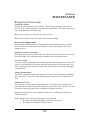
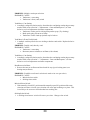
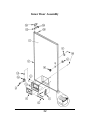
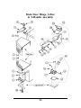
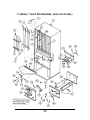
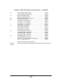
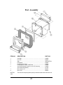
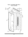
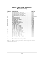
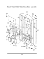
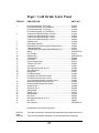
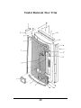
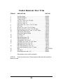
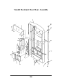
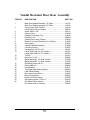
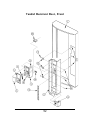
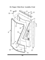
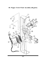
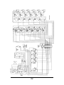
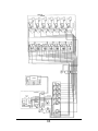
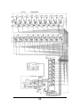
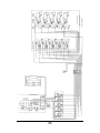
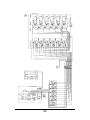
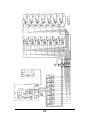
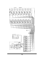
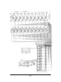
Royal Vendors'
ELECTROMECHANICAL
VENDOR
Service & Parts Manual
Includes Major Parts Explanation, Vendor Installation, Troubleshooting Tips, and
Exploded Parts View with Part Numbers
Royal Vendors, Inc.
201 Industrial Boulevard
Kearneysville WV 25430 USA
CUSTOMER SERVICE (800) 931-9214
TECHNICAL SERVICE FAX (304) 725-6579
PARTS FAX (304) 725-4016
E-mail: [email protected]
[email protected]
TABLE OF CONTENTS
SAFETY SEGMENT ................................................................................... 3
SECTION 1: GENERAL INFORMATION
Introduction ................................................................................................................ 5
Vendor Identification ................................................................................................... 5
Warranty .................................................................................................................... 7
Credit and Replacement Policy ................................................................................... 7
SECTION 2: VENDOR COMPONENT EXPLANATION
Vend Relay ................................................................................................................. 8
Sequence Relay Coil (RVCC Models Only) ................................................................ 9
Coin Mechanism ......................................................................................................... 9
Vend Motors .............................................................................................................. 10
Refrigeration System ................................................................................................... 10
SECTION 3: SET-UP AND INSTALLATION
Installation .................................................................................................................. 13
Product Shimming ....................................................................................................... 14
Adjustments (Cams and Backspacers) ........................................................................ 14
Loading Instructions .................................................................................................... 15
Testing the Vendor ...................................................................................................... 15
SECTION 4: POINTS OF INTEREST
Vend Relay Receptacle ............................................................................................... 16
Coin Mechanism Receptacle ....................................................................................... 18
Sold-Out Switches ..................................................................................................... 19
Ballast and Counter Power Sockets ............................................................................ 20
Cam Operation ........................................................................................................... 20
SECTION 5: VEND CYCLE
Vend Sequence ........................................................................................................... 24
Sold Out .................................................................................................................... 26
SECTION 6: MAINTENANCE
Taking Care of Your Vendor ........................................................................................ 27
Troubleshooting .......................................................................................................... 27
1
SECTION 7: EXPLODED VIEWS and PART NUMBERS
Inner Door Assembly .................................................................................................. 32
Main Door Hinge, Lifter, & T-Handle Assembly .......................................................... 34
Cabinet and Refrigeration System ................................................................................ 36
Cabinet, Vend Mechanism .......................................................................................... 38
Port Assembly ............................................................................................................ 41
PC / CD Main Door, Front Assembly ......................................................................... 42
PC / CD Main Door, Rear Assembly .......................................................................... 44
PC / CD Select Panel (non-electronic) ........................................................................ 46
RVCC Vandal Resistant Door Trim ............................................................................. 48
RVCC Vandal Resistant Door Rear Assembly ............................................................. 50
RVCC Vandal Resistant Door, Front ........................................................................... 52
RVCC Vandal Resistant Door, Rear ............................................................................ 54
RVDP Main Door Assembly, Front ............................................................................. 56
RVDP Main Door Assembly, Rear .............................................................................. 58
RVDP Select Panel Assembly ..................................................................................... 60
SECTION 8: WIRING DIAGRAMS ...................................................... 62
931130 - 6-select Vendors (6 Wide Col. / 0 Narrow Col.)
931029 - 6-select Vendors (6 Wide Col. / 1 Narrow Col.)
931021 - 7-select Vendors (4 Wide Col. / 4 Narrow Col.)
931023 - 9-select Vendors (1 Wide Col. / 9 Narrow Col.)
931033 - 5-select Vendors (5 Wide Col. / 0 Narrow Col.)
931119 - 6-select Vendors (6 Wide Col. / 0 Narrow Col.)
931034 - 6-select Vendors (3 Wide Col. / 3 Narrow Col.)
931097 - 7-select Vendors (6 Wide Col. / 1 Narrow Col.)
931022 - 8-select Vendors (4 Wide Col. / 4 Narrow Col.)
931024 - 10-select Vendors (1 Wide Col. / 9 Narrow Col.)
2
Safety Segment
ROYAL VENDORS’ COMMITMENT TO SAFETY
Royal Vendors is committed to safety with all of our product designs. We are committed to
notifying the user of a possible danger involving the improper handling or maintenance of our
venders. The servicing of any electrical or mechanical device involves potential dangers,
both to those servicing the equipment and to users of the equipment. These dangers can
occur because of improper maintenance or usage. The purpose of this safety segment is to
alert everyone servicing Royal equipment of potentially dangerous areas, and to provide
basic safety guidelines for proper upkeep.
The service manual contains various warnings that should be carefully read to minimize the
risk of personal injury. This manual also contains service information to insure that proper
methods are followed to avoid damaging the vender or making it unsafe. It is also important
to understand these warnings provide general guidance only. Royal could not possibly know,
evaluate, or advise of all of the conceivable ways in which service might be done. Consequently, Royal cannot predict all of the possible dangerous results. These outlined safety
precautions are the basis for an effective safety program. Use these safety measures, along
with the service bulletins, helpful hints and product specification sheets, when installing or
servicing Royal equipment.
We recommend that persons servicing our equipment maintain a similar commitment to
safety. Only personnel properly trained should have access to the interior of the
vender. This will minimize the potential dangers that are inherent in electrical and mechanical devices. Royal has no control over the vender once it leaves the premises. It is the
owner or lessor’s responsibility to maintain the vender in a safe condition. See installation
insert located in the coin box of a new vender for proper installation procedures and refer to
the service manual for recommended maintenance procedures. If you have any questions,
please contact the Technical Services Department at 1.800.931.9214.
SAFETY REGULATIONS
·
·
·
·
·
·
·
·
·
Read the safety segment before installation or service.
Test for proper grounding before installing to reduce the risk of electrical shock and fire.
Turn off or disconnect power cord from wall outlet before servicing.
Only fully trained service technicians should service vender when vender has power.
Remove any product before moving a vender.
Use appropriate equipment when moving a vender.
Always wear eye protection, and protect your hands, face, and body when working near the
refrigeration system.
Use only authorized replacement parts.
Be aware of inherent dangers in rocking or tipping a vender.
3
SECTION I: ELECTRICAL HAZARDS GENERAL ADVICE
Careless or improper handling of electrical circuits can result in injury or death. Anyone installing,
repairing, loading, opening, or otherwise servicing a vender should be aware of this precaution. Apply
all of the normal precautions when handling electrical circuits, such as:
· Refrigeration servicing to be performed by qualified personnel only.
· Unplug the vender before servicing.
· Replace electrical cords if there is any evidence of fraying or other damage.
· Keep all protective covers and ground wires in place.
· Plug equipment into outlets that are properly grounded and polarized (where applicable), and
protected with fuses or circuit breakers of the correct size.
· All electrical connections must be dry and free of moisture before applying power.
WARNING:
ALWAYS TEST TO VERIFY PROPER GROUNDING PRIOR TO INSTALLATION IN ORDER TO
REDUCE THE RISK OF ELECTRICALSHOCK AND FIRE.
SECTION II: ELECTRICAL HAZARDS
A. Servicing with Power Off
For maximum safety, unplug the power cord from the wall outlet before opening the vender door. This
will remove power from the equipment and avoid electrical hazards. Service personnel should remain
aware of possible hazards from hot components although electrical power is off.
B. Servicing with Power On
Some service situations may require access with power on. Only fully qualified service technicians
should perform power-on servicing. Particular caution is required in servicing assemblies that combine
electrical power and mechanical movement. Sudden movement (to escape mechanical action) can result
in contact with live circuits and vice versa. It is therefore important to maintain maximum clearances
from both moving parts and live circuits when servicing.
WARNINGS:
1. ONLY FULLY TRAINED PERSONNEL SHOULD ACCOMPLISH “POWER-ON” SERVICING.
SUCH SERVICE BY UNQUALIFIED INDIVIDUALS CAN BE DANGEROUS.
2. LIGHTING CIRCUITS CAN BE HAZARDOUS. ALWAYS DISCONNECT FROM POWER SUPPLY
BEFORE REPLACING A BULB OR SERVICING THE VENDER IN THAT AREA.
3. NEVER USE A HOSE, PRESSURE WASHER OR ANY CLEANING METHOD THAT COULD WET
ELECTRICAL COMPONENTS. SEE CLEANING SECTION OF MANUAL FOR SUGGESTED CLEANING METHODS. IF WATER CONTAMINATION OF ELECTRICAL COMPONENTS IS SUSPECTED,
USE QUALIFIED ELECTRICAL TESTING EQUIPMENT AND TEST METHODS TO ASSURE THAT
VENDER IS NOT A HAZARD BEFORE APPLYING POWER FOR ANY REASON.
4
5
6
7
8
9
10
11
12
13
14
15
16
17
18
19
20
21
22
23
24
25
26
SECTION 6
MAINTENANCE
Taking Care of Your Vendor
Unpack the Vendor:
Unwrap the vendor and remove any padding. Check for signs of damage at the time of
delivery. If the vendor is damaged, contact the carrier immediately. The carrier will instruct
you as to the procedure for filing a claim.
Note: The vendor keys are located in the coin return cup.
Note: Remove stretch-wrap if storing the vendor in direct sunlight.
Removing the Shipping Skids:
Separate (split) each skid section by inserting either a claw hammer, crow-bar, or similar
device into the slot of each section to break apart. Tilt the vendor slightly to remove the
separated pieces.
Placing the Vendor on Location:
When placing the vendor on location, allow for a minimum of four inches (4") of space at the
rear of the vendor. This will ensure proper ventilation of the refrigeration system.
Level the Vendor:
Level the vendor by adjusting the four leveling legs on the bottom corners of the vendor. The
vendor is level if the main door remains stationary when opened to different positions. The
four leveling legs must be in contact with the floor. This is imperative for proper drainage of
evaporator frost.
Voltage Requirements:
The vendor is designed to operate at a voltage of 115 volts, 60 hertz. It requires a minimum
of 15 amp service. The service outlet voltage must not exceed 129 VAC or fall below 103
VAC.
Vendor Power Cord:
The vendor has a 3-prong, three-wire grounding cord. The vendor must be plugged into a
grounded electrical outlet to protect the customer from an electric shock. If you are not sure
your outlet is properly grounded, have it checked by a qualified electrician.
Note: Extension cords are not recommended unless they are authorized before use by a
certified electrician.
When you plug in your vendor, you should observe the following:
1. The fluorescent lights displaying the vendor sign will come on.
2. The refrigeration compressor will start to run.
27
Troubleshooting
PROBLEM: Not accepting coins.
PROBABLE CAUSE: (Assuming the coin mechanism and vend relay are not at fault)
• No power to vendor.
• Columns are empty of product, crems circuit is dead (all sold-out lamps will be
lit).
• Crems circuit is inoperative at some point.
No Power to Vendor:
1. Check to ensure that the vendor is plugged in.
2. Make sure that the coin mechanism receptacle has power. Pin 1 should be hot with 110
VAC and pin 2 should be neutral.
Columns are Empty of Product: (All sold-out lamps will be lit)
1. Check to ensure that at least one column has enough product to depress the sold-out
paddle to allow power to reach the coin mechanism’s crems coil.
Crems Circuit is Inoperative at Some Point:
1. Follow the directional flow of electrical current to ensure that pin #6 of the coin mechanism receptacle is receiving 110 VAC (see below).
A. Starting at the extreme left vend motor and working to the right, press each individual
vend motor’s front vend switch, rotating the vend timing cam through one vend cycle
for each vend motor. If a vend motor doesn’t cycle, the problem is either in the
wiring between the problem vend motor and the vend motor to the left, -or- the vend
and/or bypass switches of the non-cycling vend motor. If all vend motors cycle
correctly then move on to step B.
B. Starting at the extreme left vend motor and working to the right, with each column
full of product (all sold-out paddles depressed), press each individual column’s front
sold-out switch (white connector) to vend from each column. This will show that
power has reached each front sold-out switch at the common position.
Note: On all RVCC model vendors, columns 1 and 2 will not vend when using the
front sold-out switches due to the wiring for sequencing.
Note: In order to enable coin mechanism acceptance, the extreme right column’s
front sold-out switch must send 115 volts from the normally closed (NC) position to
the vend relay’s common (COM) position of switch #1.
C. Check for loose connections or cut wires beneath the coin mechanism receptacle
and vend relay receptacle.
PROBLEM: Accepts coins but will not vend from one column.
PROBABLE CAUSE:
• Faulty wiring (a cut or disconnected wire)
• Select switch
• Vend relay
• Coin mechanism
28
Faulty Wiring:
1. Check to ensure that a wire connects pin #7 of the coin mechanism receptacle to the
common position of the vend relay receptacle (switch #2), and is not cut or hasn’t
disconnected.
2. Check to ensure that a wire connects the normally open (NO) position of the vend relay
receptacle (switch #2) to the common (COM) position of the extreme bottom select
switch, and isn’t cut or has not disconnected.
3. Check the select switch wiring from the normally closed (NC) position to the common
(COM) position of the next upper select switch for cuts or incomplete connections.
Select Switch:
1. If the 110 volts has reached the common (COM) position of the bottom select switch but
still no vend is allowed, replace the bottom select switch.
Vend Relay:
1. In order to power the select panel, the vend relay must disperse 110 volts out the normally open (NO) position of switch #2. If no voltage is registered at this position, check
the common (COM) position of switch #2 (from the coin mechanism). If still no voltage
is registered, change vend relay.
Coin Mechanism:
1. To energize the select panel upon credit, the coin mechanism must first send 110 volts of
electricity through pin #7 of the coin mechanism receptacle to the vend relay receptacle
(common position of the switch #2). If upon crediting pin #7 of the coin mechanism
receptacle does not register 110 volts, replace the coin mechanism.
PROBLEM: Accepts coins but will not vend from one or more columns.
PROBABLE CAUSE:
• Faulty wiring (a cut or disconnected wire)
• Defective select switch
Faulty Wiring:
1. If a selection can not be made from the extreme top select switch, or from any middle
select switch with all the select switches above inoperable, check the wire coming from
the normally closed (NC) position of the extreme top operable select switch for cuts or a
disconnection.
Defective Select Switch:
1. If all connections are correctly made and a cut can not be found, then replace the lowest
inoperable selection switch.
29
PROBLEM: Multiple vends upon selection.
PROBABLE CAUSE:
• Vend motor / cam setting
• Vend motor’s front (vend) switch
Vend Motor / Cam Setting:
1. A multiple vend upon selection may be from either the vend timing cam having too many
notches filled (refer to Section 3, “Adjustments - Cams and Backspacers”) or from
defective or out-of-adjustment vend motor components.
• Vend motor’s brake pawl is sticking from product syrup. (Try cleaning.)
• Brake pawl spring is bent out of shape
• Vend motor’s brake clutch projections may be broken.
Vend Motor’s Front (Vend) Switch:
1. A multiple vend may also be due to a sticking or broken vend switch. Replace defective
switches.
PROBLEM: Double vend, then dry vend.
PROBABLE CAUSE:
• Vend motor / cam setting
• Bent rotor (narrow column) or oscillator (wide column)
Vend Motor / Cam Setting:
1. A multiple vend upon selection may be from either the vend timing cam having too many
notches filled (refer to Section 3 - “Adjustments - Cams and Backspacers”) or from
defective or out-of-adjustment vend motor components.
Bent Rotor or Oscillator:
1. Remove the rotor or oscillator and check each for any sign of twisting (rotor) or a
bowing arm (oscillator).
PROBLEM: Establish a credit and a selection is made on its own (pre-select).
PROBABLE CAUSE:
• Miswired select switch
• Sticking select switch
Miswired Select Switch:
1. If the normally closed (NC) position and the normally open (NO) position of the same
selection switch are reversed, a pre-selection will occur upon crediting every time. This
is not likely to be seen on a vendor that has been working fine.
Sticking Select Switch:
1. A sticking select button / switch will cause a pre-select. Change select switch.
30
SECTION 7
EXPLODED VIEWS and PART NUMBERS
31
Inner Door Assembly
32
Inner Door Assembly
ITEM NO.
DESCRIPTION
1
Inner Door Assembly, 72" ............................................... 011620
Inner Door Assembly, 79" ............................................... 010620
Inner Door Gasket, 72" Wide ......................................... 815032
Inner Door Gasket, 79" ................................................... 815033
Port Door Frame ............................................................ 815013
Port Door ....................................................................... 815014
Port Door Rod ................................................................ 811004
Elastic Stop Nut #6-32 ................................................... 905006
Latch Strike (for inner door) ........................................... 812003
Bushing, 1.37" ................................................................ 916003
Cable Clamp, 1" ............................................................. 916004
Rivet, 3/16" diameter...................................................... 908002
Inner Door Bushing ........................................................ 815026
Inner Door Hinge ............................................................ 010520
Nut, #8-32 ...................................................................... 905001
Self-drilling Screw, #8-18 x 1/2" ..................................... 010543
Bottom Door Hinge ........................................................ 010543
Bolt, 1/4-20 x 1" .............................................................. 901003
2
3
4
5
6
7
8
9
10
11
12
13
14
15
16
PART NO.
33
Main Door Hinge, Lifter,
& T-Handle Assembly
34
Main Door Hinge, Lifter,
& T-Handle Assembly
ITEM NO.
DESCRIPTION
1
2
3
4
5
6
7
8
9
10
11
12
13
14
15
16
17
18
19
20
21
22
23
24
25
26
Top Hinge Assembly....................................................... 810002
Bearing, Nyliner 1/2"....................................................... 916012
Nut, 5/8" ......................................................................... 905007
Self-tapping Bolt, 1/4-20 x 1" .......................................... 901003
Carriage Bolt, 1/4-20 x 1" ............................................... 901008
Nut, 1/4-20 ..................................................................... 905002
Flat Washer, 7/8" OD ..................................................... 904002
Bottom Hinge Assembly ................................................. 010040
Top Hinge Spacer ........................................................... 010016
Door Roller Spacer (as required) ................................... 010015
Door Roller Bracket ....................................................... SEE NOTE #2
Door Roller ..................................................................... SEE NOTE #2
Door Roller Pin .............................................................. SEE NOTE #2
Retaining Ring, 5/32" ..................................................... 906005
Key ................................................................................. SEE NOTE #1
Lock ............................................................................... SEE NOTE #1
T-Handle Body (all except Vandal Res. Door) ................ 812134
Pin, T-Handle ................................................................. 912133
T-Handle Stud ................................................................ 803006
Spring ............................................................................. SEE NOTE #2
Retainer Ring ................................................................. SEE NOTE #2
Nut Retainer ................................................................... 010028
Latch Strike .................................................................... 010027
Square Nut, 1/2-13 x 3/4" ............................................... 905005
Latch Strike Assembly .................................................... 010030
T-Handle Assembly ........................................................ 812001
T-Handle Assembly (all Vandal Resistant Doors)........... 812176
Door Lifter Assembly...................................................... 815030
Leveling Leg ................................................................... 803002
27
28
PART NO.
NOTE #1:
There are various parts. Please specify model and serial number at
the time of order.
NOTE #2:
bly.
This part is not available individually. It must be ordered as an assem-
35
Cabinet and Refrigeration System
36
Cabinet and Refrigeration System
ITEM NO.
DESCRIPTION
1
Foamed Cabinet Assy., 72" Wide 2-deep* .............................. 011220
Foamed Cabinet Assy., 72" Wide 3-deep* .............................. 058220
Foamed Cabinet Assy., 79" Wide 2-deep* .............................. 010230
Evaporator Fan Shroud Assembly ........................................... 010010
Evaporator Cover ..................................................................... 010013
Grommet - Evap. Fan Motor (not shown) ................................. 916006
Fan Blade, Evaporator ............................................................ 810004
Fan Motor, Evaporator ............................................................. 839001
Evaporator Fan Plate .............................................................. 010058
Fan Motor Bracket, Evaporator ............................................... 010006
Self-tapping Bolt, 1/4-20 x 1" .................................................. 901003
U-clip ...................................................................................... 906007
Self-drilling Screw, #8 x 1/2" ................................................... 902004
Fan Motor, Condenser ............................................................ 839010
Fan Blade, Condenser ............................................................ 810003
Fan Motor Bracket, Condenser ............................................... 810006
Compressor ............................................................................ SEE NOTE #1
1/3+ H.P. Refrigeration System w/Capacitor ........................... 156430
1/3 H.P. Refrigeration System w/Capacitor .............................. 141420
Screw, #8-32 x 3/8" ................................................................ 901011
Main Wiring Harness, Electro-Mechanical .............................. 842005
Condensate Pan ..................................................................... 810005
Sponge ................................................................................... 815037
Wiring Cover Plate .................................................................. 010002
Grommet Plug ........................................................................ 815017
Compressor Clip ..................................................................... 914002
Relay 1/3 Tecumseh (not shown) ............................................ 822002
Relay 1/3+ Tecumseh (not shown) .......................................... 822009
Overload 1/3 Tecumseh (not shown) ........................................ 822004
Overload 1/3+ Tecumseh (not shown) ..................................... 822010
Silencer .................................................................................. 939037
Screw, #8-32 x 1/2" ................................................................ 901038
Well Nut (Rubber), #8-32 ........................................................ 905026
Nut, 1/4-20** ........................................................................... 905002
Mounting Bracket, Evaporator Fan Plate ................................. 010057
2
3
4
5
6
7
8
9
10
11
12
13
14
15
16
17
18
19
20
21
22
23
24
25
26
27
28
29
30
*
**
ing this nut.
NOTE #1:
PART NO.
Denotes that a color must be specified.
Denotes that Loc-Tite threadlocker #262 is used on motor shaft before mountThis part is not available individually. It must be ordered as an assembly.
37
Cabinet, Vend Mechanism (non-electronic)
38
Cabinet, Vend Mechanism (non-electronic)
ITEM NO.
DESCRIPTION
1
25
26
27
28
29
Foamed Cabinet Assembly, 72" Wide 2-deep .......................... 011220
Foamed Cabinet Assembly, 72" Wide 3-deep .......................... 058220
Foamed Cabinet Assembly, 79" Wide 2-deep .......................... 010230
Vend Mechanism Assembly .................................................... SEE NOTE #1
Hem Channel Cap ................................................................... 815024
Left Cabinet Vandal Panel, 79" (1302 & after)* ......................... 141002
Left Cabinet Vandal Panel, 72" (1302 & after)* ......................... 142001
Left Cabinet Vandal Panel, 79" (before 1302) ........................... 010022
Left Cabinet Vandal Panel, 72" (before 1302) ........................... 011001
Backspacer Assembly, Narrow Column ................................... SEE NOTE #1
Backspacer Assembly, Wide Column ...................................... SEE NOTE #1
Spring, Backspacer ................................................................. 914001
Latch, Gate ............................................................................. 010725
Mechanism Gate Weld Assembly ........................................... SEE NOTE #1
Hinge, Gate ............................................................................. 010726
Mechanism Support, 2-deep ................................................... 010005
Thermostat Bracket / Mechanism Support, 2-deep .................. 010020
Mechanism Support, 3-deep ................................................... 058001
Thermostat Bracket / Mechanism Support, 3-deep .................. 058010
Pop Rivet, 1/8" ........................................................................ 908001
Can Chute Bracket .................................................................. 010018
Can Chute Tie Bracket ............................................................ 010017
Washer, Nylon 1/2" ID ............................................................. 904001
Linkage Arm (Wide Column Motor only) .................................. 809005
Nyliner, 3/8" ............................................................................ 916011
Rotor Retainer (Narrow Column only) ....................................... 815012
Screw, #8-32 x 3/8" ................................................................. 901011
Journal Plate (Wide Column only) ........................................... 010708
Nyliner, 1/2" ............................................................................ 916010
Rotor, 2-deep (Narrow Column only) ........................................ 809002
Rotor, 3-deep (Narrow Column only) ........................................ 809007
Oscillator, 2-deep (Wide Column only) .................................... 809003
Oscillator, 3-deep (Wide Column only) .................................... 809008
Vend Motor Assy. (Wide Col.) - Regular 2-deep ....................... 010730
Vend Motor Assy. (Wide Col.) - Regular 3-deep ....................... 059760
Vend Motor Assy. (Narrow Col.) - Regular 2-deep .................... 010720
Vend Motor Assy. (Narrow Col.) - Regular 3-deep .................... 059770
Self-tapping Screw with Star Washer ....................................... 901006
Self-tapping Screw, 1/4-20 x 1" ............................................... 901003
Screw, #4 x 1 1/8" ................................................................... 902003
Cabinet Harness (not shown) .................................................. SEE NOTE #1
Miniature Switch ..................................................................... 835001
30
Switch Insulator / Spacer ................................................ 815016
31
32
Sold-out Bar ............................................................................ SEE NOTE #1
Sold-out Spring ........................................................................ 914003
2
3
4
5
6
7
8
9
10
11
12
13
14
15
16
17
18
19
20
21
22
23
24
PART NO.
39
Cabinet, Vend Mechanism (non-electronic) - continued
33
34
35
36
37
38
39
40
•
•
•
*
NOTE #1:
of order.
Sold-out Paddle, Wide Column ..............................................
Sold-out Paddle, Narrow Column ............................................
Motor Cover, Wide Cabinet .....................................................
Motor Cover, Narrow Cabinet ..................................................
Wide Can Chute Assembly, 2-deep ........................................
Can Chute Liner, Wide ...........................................................
Hem Angle - Left - 2-deep, 79" ...............................................
Hem Angle - Left - 2-deep, 72" ...............................................
Hem Angle - Left - 3-deep, 79" ...............................................
Hem Angle - Left - 3-deep, 72" ...............................................
Hem Channel - 2-deep, 79" ....................................................
Hem Channel - 2-deep, 72" ....................................................
Hem Channel - 3-deep, 79" ....................................................
Hem Channel - 3-deep, 72" ....................................................
Hem Angle - Right - 2-deep, 79" .............................................
Hem Angle - Right - 2-deep, 72" .............................................
Hem Angle - Right - 3-deep, 79" .............................................
Hem Angle - Right - 3-deep, 72" .............................................
Self-tapping Screw, 1/4-20 x 1" ..............................................
Rear Can Retainer (not shown) ...............................................
Wire Tie, 4" (not shown - holds S.O. Harness) .......................
Wire Tie, Large (not shown)....................................................
010729
010731
010029
036003
010070
010021
010717
011708
058711
059707
010715
011711
058709
059706
010716
011709
058712
059708
901003
810007
916007
916008
Denotes that a color must be specified.
There are various parts. Please specify model and serial number at the time
40
Port Assembly
ITEM NO.
DESCRIPTION
1
2
3
4
5
Can Stop ................................................................................. 010508
Port Trim ................................................................................. 815019
Sign ........................................................................................ SEE NOTE #1
Port Spacer ............................................................................ 815020
Port Body W/A, Coke ............................................................. 010530
Port Body W/A, Pepsi / Cold Drink ......................................... 012560
Anti-Theft Plate (all except 16 oz. & CDC Vendors) ................ 010509
Anti-Theft Plate (Bottles) ......................................................... 141102
Bolt 1/4-20 x 1/2" .................................................................... 901007
Nut 1/4-20 ............................................................................... 905002
6
7
8
NOTE #1:
order.
PART NO.
There are various parts, please specify model and serial number at the time of
41
Pepsi / Cold Drink Main Door,
Front Assembly
42
Pepsi / Cold Drink Main Door,
Front Assembly
ITEM NO.
DESCRIPTION
1
14
Door Weld Assembly, 79" (Pepsi)* ................................ 012520
Door Weld Assembly, 79" (Cold Drink)*......................... 020510
Door Weld Assembly, 72" (Pepsi)* ................................ 013510
Door Weld Assembly, 72" (Cold Drink)*......................... 019510
Sign ................................................................................ SEE NOTE #1
Right Vandal Panel, 79" .................................................. 010519
Right Vandal Panel, 72" .................................................. 011501
Rain Guard, Wide Vendors ............................................ 010518
Top Door Hinge .............................................................. 810002
Carriage Bolt, 1/4-20 x 1/2" ............................................ 901007
Self-drilling Screw, #8-18 x 1/2" ..................................... 902004
T-screw, #8-32 x 3/4" ..................................................... 901001
Top Door Bushing .......................................................... 803003
Left Side Trim, 79" (Pepsi) ............................................. 141553
Left Side Trim, 72" (Pepsi) ............................................. 142502
Left Side Trim, 79" (Cold Drink) ..................................... 032505
Left Side Trim, 72" (Cold Drink) ..................................... 019507
Top Trim, 79" & 72" (Pepsi) ............................................ 012533
Top Trim, 79" & 72" (Cold Drink) .................................... 032504
Bottom Trim, 79" & 72" (Pepsi) ...................................... 012533
Bottom Trim, 79" & 72" (Cold Drink) .............................. 032507
Right Side Trim, 79" (Pepsi) .......................................... 012554
Right Side Trim, 72" (Pepsi) .......................................... 013507
Right Side Trim, 79" (Cold Drink) ................................... 032506
Right Side Trim, 72" (Cold Drink) ................................... 019508
Pop Rivet, Stainless Steel, 1/8" diameter ....................... 908001
*
Denotes that a color must be specified.
2
3
4
5
6
7
8
9
10
11
12
13
PART NO.
NOTE #1:
There are various part numbers. Please specify model and serial
number at the time of order.
43
Pepsi / Cold Drink Main Door, Rear Assembly
44
Pepsi / Cold Drink Main Door, Rear Assembly
ITEM NO.
DESCRIPTION
1
11
12
13
14
15
16
17
18
19
20
21
22
23
24
25
26
27
28
Door Weld Assembly, 79" (Pepsi)* .................................. 012520
Door Weld Assembly, 79" (Cold Drink)*........................... 020510
Door Weld Assembly, 72" (Pepsi)* .................................. 013510
Door Weld Assembly, 72" (Cold Drink)*........................... 019510
Port Body W/A, PC / CD (Wide Round) .......................... 012560
Lamp Guard, Wide .......................................................... 012514
Lamp Guard, Narrow ....................................................... 040501
Port Brace, Wide ............................................................. 010515
72" Slimline Lamp (for 79" vender) .................................. 841005
64" Slimline Lamp (for 72" vender) .................................. 841006
Coin Box Housing ............................................................ 010537
Coin Box Welded Assembly ............................................ 010580
Coin Hopper ..................................................................... 815015
Changer Door .................................................................. 010544
Changer Door Assembly .................................................. 011580
Ballast Assembly, 79" (with Lampholders & Wire) ........... 012591
Ballast Assembly, 72" (with Lampholders & Wire) ........... 013920
Lamp Bracket .................................................................. 010517
Top Lampholder ............................................................... 842003
Bottom Lampholder ......................................................... 842004
Changer Door Hinge, Top ................................................ 010525
Changer Door Hinge, Bottom........................................... 010524
Bottom Hinge, Inner Door Hinge Assembly ...................... 010550
Latch Roller Bracket ........................................................ 010516
Latch Strike (for Inner Door) ............................................. 812003
Screw, 1/4-20 x 1" ............................................................ 901003
Self-drilling Screw, #8-18 x 1/2" ....................................... 902004
Carriage Bolt, 1/4-20 x 1/2" .............................................. 901007
Nut, 1/4-20 ....................................................................... 905002
Screw, #8-32 x 3/8" .......................................................... 901011
Pop Rivet, 1/8" ................................................................. 908004
Bottom Coin Chute Assy., PC / CD (to Coin Box) ............ 012593
Hopper Chute Assembly (to Coin Cup) ............................ 012538
Tie Rod, Door ................................................................... 811001
Elastic Stop Nut, #8-32 .................................................... 905004
*
Denotes that a color must be specified.
2
3
4
5
6
7
8
9
10
PART NO.
45
Pepsi / Cold Drink Select Panel
46
Pepsi / Cold Drink Select Panel
ITEM NO.
DESCRIPTION
1
22
23
24
25
26
27
28
29
30
31
32
Door Weld Assembly, 79" (Pepsi)* ............................................ 012520
Door Weld Assembly, 79" (Cold Drink)* .................................... 020510
Door Weld Assembly, 72" (Pepsi)* ............................................ 013510
Door Weld Assembly, 72" (Cold Drink)* .................................... 019510
Control Panel Weld Assembly, 10-select* ................................. 017530
Control Panel Weld Assembly, 8-select .................................... 012510
Control Panel Weld Assembly, 7-select .................................... 034520
Control Panel Weld Assembly, 6-select .................................... 040530
Validator Cover .......................................................................... 012508
Panel Strap (optional) ............................................................... 010531
Relay Bracket (houses Changer & Relay Recept.) .................... 010522
T-Handle Assembly ................................................................... 812001
T-Handle Body (all except Vandal Resistant Door) .................... 812134
Spring ....................................................................................... SEE NOTE #2
Pin, T-Handle ............................................................................ 912133
Retainer Ring ............................................................................ SEE NOTE #2
T-Handle Stud ........................................................................... 803006
Coin Insert ................................................................................ 809006
Correct Change Lamp ............................................................... 841010
T-Screw, 8-32 x 3/4" .................................................................. 901001
Coin Chute ................................................................................ 815001
Self-tapping Screw, #6-32 x 1/4" ............................................... 901004
Coin Chute Cover ...................................................................... 815002
Spring Plate .............................................................................. 010511
Coin Return Spring .................................................................... 914003
Scavenger Link (Coin Return Lever) ........................................... 810001
Coin Return Cup (old style, Lexan) ........................................... 815003
Coin Cup Weld Assembly (new style, steel) ............................. 012595
Button Assembly (button front shown) ....................................... 815025
Button Assembly (button rear shown) ....................................... 815025
Sold Out Lamp ......................................................................... 841009
Screw, #4-40 x 1" ..................................................................... 901005
Spring Shield ............................................................................ 815164
Switch, Large ............................................................................ 835012
Switch Spacer .......................................................................... 815018
Nut, #4-40 ................................................................................. 905003
Self-tapping Screw, #8-32 x 1/2" ............................................... 901002
Nut, #8-32 ................................................................................. 905001
Door Harness ............................................................................ SEE NOTE #1
*
Denotes that a color must be specified.
NOTE #1:
order.
NOTE #2:
There are various parts. Please specify model and serial number at the time of
2
3
4
5
6
7
8
9
10
11
12
13
14
15
16
17
18
19
20
21
PART NO.
This part is not available individually. It must be ordered as an assembly.
47
Vandal Resistant Door Trim
48
Vandal Resistant Door Trim
ITEM NO.
DESCRIPTION
1
2
3
4
5
19
20
21
Top Door Hinge .............................................................. 810002
Top Door Bushing .......................................................... 803003
T-Screw, #8-32 .............................................................. 901001
Top Trim, Coke, 72" & 79" Wide ..................................... 141552
Left Trim, Coke, 79" ....................................................... 141553
Left Trim, Coke, 72" ....................................................... 142502
Right Insert Trim, Coke, 72" & 79" Wide ........................ 141556
Port Trim ........................................................................ 815019
Bottom Trim, Coke, 72" & 79" Wide ............................... 141552
Bottom Insert Trim, Coke, 72" & 79" Wide ..................... 141558
Right Side Bottom Trim, Coke, 72" & 79" Wide ............. 141555
Rain Guard, Wide Vendor .............................................. 010518
Rain Guard, Narrow Vendor ........................................... 036503
Pop Rivet, 1/8" ............................................................... 908001
Nut, 1/4-20 ..................................................................... 905002
Right Vandal Panel, 79"* ................................................ 010519
Right Vandal Panel, 72"* ................................................ 011501
Carriage Bolt, 1/4-20 x 1/2" ............................................ 901007
Top Insert Trim, Coke, 72" & 79" Wide ........................... 141557
Right Side Top Trim, Coke, 79" ...................................... 141554
Right Side Top Trim, Coke, 72" ...................................... 142503
Door Weld Assembly, Coke, 79" .................................... 141510
Door Weld Assembly, Coke, 72" Wide .......................... 142510
Sign ................................................................................ SEE NOTE #1
Nut, #8-32 ...................................................................... 905001
Self-drilling Screw, #8 x 1/2" .......................................... 902004
*
Denotes that a color must be specified.
6
7
8
9
10
11
12
13
14
15
16
17
18
PART NO.
NOTE #1:
There are various parts. Please specify model and serial number at
the time of order.
49
Vandal Resistant Door Rear Assembly
50
Vandal Resistant Door Rear Assembly
ITEM NO.
DESCRIPTION
1
Main Door Welded Assembly, 79" Wide........................... 141510
Main Door Welded Assembly, 72" Wide........................... 142510
Lamp Guard, Wide Vendors ............................................ 012514
Lamp Guard, Narrow Vendors ......................................... 040501
Screw, #8-32 x 3/8" .......................................................... 901011
Changer Door .................................................................. 010544
Changer Door Hinge, Top ................................................ 010525
Pop Rivet, 1/8" ................................................................. 908004
Changer Door Hinge, Bottom........................................... 010524
Bottom Coin Chute Assembly (to Coin Box) .................... 012593
Coin Hopper ..................................................................... 815015
Coin Box Welded Assembly ............................................ 010580
Coin Box Housing ............................................................ 010537
Carriage Bolt, 1/4-20 x 1/2" .............................................. 901007
Lamp, High Output for 79" Vendors ................................. 841001
Lamp, High Output for 72" Vendors ................................. 841002
Tie Rod ............................................................................ 811001
Keps Nut, 1/4-20 .............................................................. 905002
Ballast Assembly, 79" Wide Vendors ............................... 010950
Ballast Assembly, 72" Wide Vendors ............................... 011930
Self-drilling Screw, #8-32 ................................................. 902004
Elastic Stop Nut ............................................................... 905004
Lamp Bracket .................................................................. 010517
Top Lampholder (Spring-loaded) ...................................... 842001
Latch Roller Bracket ........................................................ 010516
Burst Open Latch Strike ................................................... 812003
Bottom Lampholder ......................................................... 842002
Bottom Inner Door Hinge ................................................. 010550
Self-tapping Screw, 1/4-20 x 1" ........................................ 901003
Port Brace, Wide Vendors ............................................... 010515
Port Brace, Narrow Vendors ............................................ 036502
2
3
4
5
6
7
8
9
10
11
12
13
14
15
16
17
18
19
20
21
22
23
24
25
26
PART NO.
51
Vandal Resistant Door, Front
52
Vandal Resistant Door, Front
ITEM NO.
DESCRIPTION
1
Door Welded Assembly, Coke, 79" .................................. 141510
Door Welded Assembly, Coke, 72" .................................. 142510
Control Panel, Coke, 6-select .......................................... 145510
Control Panel, Coke, 7-select .......................................... 141502
Control Panel, Coke, 9-select .......................................... 143510
Security Plate Welded Assembly ..................................... 141550
Validator Cover, Coke ....................................................... 010535
Security Plate Decal, Non-electronic ............................... 845397
T-Bolt, 1/4-20 x 1" ............................................................ 901037
Bushing, Button Coin Return ........................................... 803030
Hex Jam Nut, 9/16-18 UNF2A .......................................... 905019
Screw, #8-32 x 3/8" .......................................................... 901011
Coin Plate, Coke .............................................................. 141516
Keps Nut, 1/4-20 .............................................................. 905002
Hold Down Angle .............................................................. 123505
Decal, Select Button ........................................................ 845383
Coin Cup Mounting Plate Welded Assembly .................... 123550
Carriage Bolt, 1/4-20 x 1/2" .............................................. 901007
Correct Change Lamp ..................................................... 841010
2
3
4
5
6
7
8
9
10
11
12
13
14
15
16
PART NO.
53
Vandal Resistant Door, Rear
54
Vandal Resistant Door, Rear
ITEM NO.
DESCRIPTION
1
Door Welded Assembly, Coke, 79" ................................ 141510
Door Welded Assembly, Coke, 72" ................................ 142510
Flush Mount “Pop-Out” T-Handle Assembly ................... 812176
Flush Mount T-Handle Body ........................................... N/A
Spring ............................................................................. N/A
T-Handle Stud ................................................................ N/A
Retaining Ring ............................................................... N/A
Pin / T-Handle Stud ........................................................ N/A
Sold Out Spring .............................................................. 914003
Button, Coin Return Lever ............................................. 803031
Retaining Ring, 5/32....................................................... 906005
Roller Pin, Door Lifter ..................................................... 811002
Hinge, Coin Return Lever ............................................... 141506
Coin Return Lever .......................................................... 141504
Catch Basin, Bill Validator .............................................. 095509
Catch Basin, Drain Tube ................................................ 825038
POS Window, Coke ....................................................... 815007
POS Window Plate ........................................................ 123503
Security Shelf ................................................................. 141512
T-Handle Housing .......................................................... 812190
T-Handle Brace .............................................................. 141513
Lever Stop ...................................................................... 141514
Coin Chute ..................................................................... 815001
Coin Chute Cover .......................................................... 815002
Splash Guard, Coke ....................................................... 815169
Coin Ramp ..................................................................... 141508
Spring, Select Button ..................................................... 914004
Select Button, Coke ....................................................... 815165
Switch, Miniature ............................................................ 835009
Carrier Strip Assembly ................................................... 815167
Button Panel .................................................................. 815168
Retaining Strap .............................................................. 141507
Screw, #8-32 x 3/8" ........................................................ 901011
Self-drilling Screw, #8 x 1/2" .......................................... 902001
Screw, #6-32 x 3/8" ........................................................ 901004
Nut, #8-32 ...................................................................... 905001
Nut, 1/4-20 ..................................................................... 905002
Wire Tie, Large (4") ........................................................ 916008
Sold Out Lamp ............................................................... 841009
2
3
4
5
6
7
8
9
10
11
12
13
14
15
16
17
18
19
20
21
22
23
24
25
26
27
28
29
30
31
32
33
34
35
36
37
38
PART NO.
55
Dr. Pepper Main Door Assembly, Front
56
Dr. Pepper Main Door Assembly, Front
ITEM NO.
DESCRIPTION
PART NO.
1
15
16
17
Main Door Welded Assembly, Dr. Pepper, 79"*
Main Door Welded Assembly, Dr. Pepper, 72"*
Right Vandal Panel, 79"*
Right Vandal Panel, 72"*
Rain Guard, Wide
Top Hinge, Left
Nyliner, 1/2"
T-Screw, #8-32 x 3/4"
Carriage Bolt, 1/4-20 x 1/2"
Pop Rivet, 1/8"
Sign
Trim, Dr. Pepper, 79", Vertical Left Side
Trim, Dr. Pepper, 72", Vertical Left Side
Trim, Dr. Pepper, 79", Top & Bottom
Trim, Dr. Pepper, 72", Top
Trim, Dr. Pepper, 79" & 72", Bottom
Trim, Vertical Top Right Side (79" Vendor only)
Trim, Dr. Pepper, 79", Control Panel Side
Trim, Dr. Pepper, 72", Control Panel Side
Trim, Dr. Pepper, 79" & 72", Bot. Cont. Pnl. Side
Trim, Dr. Pepper, 79" & 72", Vert. Bot. Right Side
Self-drilling Screw, #8 x 1/2"
100510
101510
010519
011501
010518
810002
916012
901001
901007
908004
SEE NOTE #1
141553
019507
141552
101502
141552
100518
100517
101503
100516
100515
902004
*
Denotes that a color must be specified.
2
3
4
5
6
7
8
9
10
11
12
13
14
NOTE #1:
There are various parts. Please specify model and serial number at
the time of order.
57
Dr. Pepper Main Door Assembly, Rear
58
Dr. Pepper Main Door Assembly, Rear
ITEM NO.
DESCRIPTION
1
7
8
9
10
11
12
13
14
15
16
17
18
19
20
21
22
23
Main Door Welded Assembly, Dr. Pepper, 79"* ............... 100510
Main Door Welded Assembly, Dr. Pepper, 72"* ............... 101510
High Output Ballast Assembly, 79" ................................... 100930
High Output Ballast Assembly, 72" ................................... 101910
Screw, #8-32 x 1/2" .......................................................... 901002
Elastic Stop Nut, #8-32 .................................................... 905004
Lamp Guard, Wide .......................................................... 012514
Changer Door .................................................................. 010544
Changer Door Assembly .................................................. 011580
Coin Hopper ..................................................................... 815015
Pop Rivet, 1/8" ................................................................. 908004
Self-drilling Screw, #8-18 x 1/2" ....................................... 902004
Latch Strike (for Inner Door) ............................................. 812003
Latch Roller Bracket ........................................................ 010516
Changer Door Hinge, Bottom........................................... 010524
Bottom Coin Chute Assembly .......................................... 010594
Coin Box Weld Assembly ................................................ 010580
Coin Box Housing ............................................................ 010537
Screw, 1/4-20 x 1" ............................................................ 901003
Nut, 1/4-20 ....................................................................... 905002
Carriage Bolt, 1/4-20 x 1" ................................................. 901007
Bottom Lampholder, High Output ..................................... 842002
Lamp Bracket .................................................................. 010517
Tie Rod, Door ................................................................... 811001
Top Lampholder, High Output........................................... 842001
Changer Door Hinge, Top ................................................ 010525
*
Denotes that a color must be specified.
2
3
4
5
6
PART NO.
59
Dr. Pepper Select Panel Assembly (Regular)
60
Dr. Pepper Select Panel Assembly (Regular)
ITEM NO.
DESCRIPTION
1
13
14
15
16
17
18
19
20
21
22
23
24
25
26
27
28
29
Main Door Welded Assembly, Dr. Pepper, 79"* ......................... 100510
Main Door Welded Assembly, Dr. Pepper, 72"* ......................... 101510
Control Panel, Dr. Pepper, Front - 10-select .............................. 815086
Control Panel, Dr. Pepper, Front - 8-select ................................ 815071
Control Panel, Dr. Pepper, Front - 6-select ................................ 815088
Control Panel, Dr. Pepper, Rear - 10-select ............................... 815087
Control Panel, Dr. Pepper, Rear - 8-select ................................. 815072
Control Panel, Dr. Pepper, Rear - 6-select ................................. 815089
Select Button, Dr. Pepper ......................................................... 815073
Button Spring, Dr. Pepper ......................................................... 914020
Switch, Miniature ...................................................................... 835001
Self-drilling Screw, #8-18 x 1/2" ................................................ 902004
Screw, #4 x 5/8" ....................................................................... 902009
Nut, #8-32 ................................................................................. 905001
Main Door Harness ................................................................... SEE NOTE #1
Sold Out Lamp ......................................................................... 841009
Coin Return Cup (old style, Lexan) ........................................... 815003
Coin Return Cup Welded Assembly (1218 & after) .................... 100560
Coin Insert ................................................................................ 809006
Correct Change Lamp ............................................................... 841010
T-Handle Assembly ................................................................... 812001
T-Handle Body .......................................................................... 812134
Spring ....................................................................................... SEE NOTE #2
Pin, T-Handle ............................................................................ SEE NOTE #2
T-Handle Stud ........................................................................... 803006
Retainer Ring ............................................................................ 906005
Coin Chute ................................................................................ 815001
Self-tapping Screw, #6-32 x 1/4" ............................................... 901004
Coin Chute Cover ...................................................................... 815002
Spring Plate .............................................................................. 010511
Coin Return Spring .................................................................... 914003
Scavenger Link (Coin Return Lever) ........................................... 810001
Validator Cover .......................................................................... 012508
Panel Strap (optional) ............................................................... 010531
Lock Cylinder Cover .................................................................. 161532
*
Denotes that a color must be specified.
NOTE #1:
order.
NOTE #2:
There are various parts. Please specify model and serial number at the time of
2
3
4
5
6
7
8
9
10
11
12
PART NO.
This part is not available individually. It must be ordered as an assembly.
61
62
63
64
65
66
67
68
69
70
71
Made in the
United States of America
Royal Vendors’ Publication
010127
Rev. D 7-03
72