1
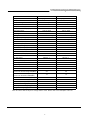
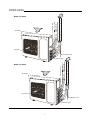
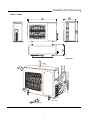
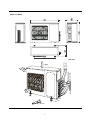
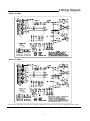
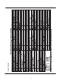
SERVICE MANUAL
FREE COMBI SERIES
FC-E24AI, FC-E28AI
1.Technical specifications
Model
FC-E24AI
FC-E28AI
Shenyang SANYO /SANYO
Shenyang SANYO /SANYO
Compressor Model
C-7RZ233H1A
C-7RZ233H1A
Compressor Type
Rotary
Rotary
Compressor Manufacturer/trademark
L.R.A. (A)
34
34
Compressor RLA(A)
8.2
8.2
Compressor Power Input(W)
Overload Protector
Throttling Method
Starting Method
Working Temp Range (℃)
Condenser
Pipe Diameter (mm)
Rows-Fin Gap(mm)
1760
1760
1NT11L-3979
1NT11L-3979
Electronic Expansion Valve
Electronic Expansion Valve
Transducer starting
Transducer starting
-7℃?T?43℃
-7℃?T?43℃
Aluminum fin-copper tube
Aluminum fin-copper tube
Φ9.52
Φ9.52
2-1.4
2-1.4
Coil length(l) x height(H) x coil width(L)
806X813X44
806X813X44
Fan Motor Speed (rpm) (H/M/L)
860/760/540
860/760/540
Output of Fan Motor (W)
60
60
Fan Motor RLA(A)
0.3
0.3
3
3
Fan Motor Capacitor (uF)
Air Flow Volume of Outdoor Unit
Fan Type-Piece
/
/
Axial fan –1
Axial fan –1
460
460
Auto defrost
Auto defrost
T1
T1
Fan Diameter (mm)
Defrosting Method
Climate Type
Isolation
Moisture Protection
Permissible Excessive Operating
Pressure for the Discharge Side(MPa)
Permissible Excessive Operating
Pressure for the Suction Side(MPa)
Sound Pressure Level dB (A) (H/M/L)
Sound Power Level dB (A) (H/M/L)
Dimension (W/H/D) (mm)
Dimension of Package (L/W/H)(mm)
Net Weight /Gross Weight (kg)
Refrigerant Charge (kg)
I
I
IP24
IP24
3.8
3.8
1.2
1.2
60/54
60/54
69/68
69/68
950X840X420
950X840X420
1100X450X905
1100X450X905
75/80
75/80
R410a/3.3
R410a/3.3
Note: The above data is subject to change without notice. Please refer to the nameplate of the unit.
2
2.Part name
Connection wire
Model: FC-E24AI
Air intake
Air outlet
Drainage hose
Connection pipe
Connection wire
Model: FC-E24AI
Air intake
Air outlet
Drainage hose
Connection pipe
3
3.Outline and dimension
Model: FC-E24AI
Unit: mm
Bolt
Nut
Wrench
4
Model: FC-E28AI
Unit: mm
Bolt
Nut
Wrench
5
4.Wiring Diagram
Model: FC-E24AI
Model: FC-E28AI
These circuit diagrams are subject to change without notice, please refer to the one supplied with the unit.
6
5.Operation
1.Temperature parameters
Indoor ambient temperature (Tinner ambient)
Indoor setting temperature (Tset)
2.System first power on
After electrified, the side valve will be powered on, each electron expansion valve will be turned off orderly, then side valve will be powered off,
all the electron expansion valve should be turned to a certain angle, the unit on is standby.
Under each modes, once the compressor starts up, at least running for 7mins the unit will stop (not including
malfunction protection, modes switch the compressor needed to stop running);
Once compressor stopped, the unit will start up after 3mins delay (Heating oil return or defrosting except).
2.1 Cooling mode
Working condition and procedure of cooling running
If compressor stopped and turn on the unit for cooling, if any one indoor unit (Tindoor amb. Tpreset) 0.5 , that the cooling will run;
at this time, the outdoor fan motor, compressor starts to run, the compressor frequency will run at the capacity requirement calculated.
2.1.2 Unit will stop for cooling
(1) Compressor will stop running
Compressor will stop running right away, outdoor fan motor will delay 1min and will stop running, all the electron expansion valve starts to work, when
turns off all valves at OP, the side valve will be electrified, the valve fully turns to 480P, the side valve will turn off.
(2) Part of indoor unit arrive at unit stop running condition (Compressor will not stop)
Compressor will run according to capacity requirement calculated frequency, when capacity requirement is 0 indoor unit corresponding electron
expansion valve 5s turns off, compressor frequency variable start meanwhile running indoor unit (no matter it is newly opened or indoor unit
has been run) the corresponding electron expansion valve resumes to the original value.
NOTE: Unit off, Fan, Protection as the same with Cool mode;
2.1.3 Switching from cooling mode to heating mode
When turning to heating mode, after compressor stopped, 4-way valve will electrify after 2mins delay, the others are the same with cooling.
2.1.4 4-way valve control
Under this mode, 4-way valve will close (that is not electrified).
Outdoor unit fan motor control under cooling mode
Before compressor start 5s start cooling, after outdoor fan motor start up and run in high speed for 3min, then according to the indoor unit rated capacity
total amount and outdoor ambient temperature, automatically select High, Mid, Low three fan speeds.
Other control: When the newly opened indoor unit is running, outdoor fan motor will run at high fan speed for 40s, then according to control logic to
adjust. Fan motor each grade at least run 80s (when indoor unit running quantities change and calculate indoor unit rated capacity total amount
and according to temperature to adjust the fan speed.) When compressor stops running, outdoor fan will run at
When cooling oil return, after compressor frequency rise up to 70Hz, it will stayabily run; Outdoor fan motor will accord to indoor unit will run at current
fan speed and after 1min delay to stop.
Cooling oil return condition
rating capacity total capacity and temperature automatically adjust the fan speed.
The oil return lasting time of cooling will be 5min. (including frequency rising time), oil return will be completed.
Anti-freezing protection
When it is satisfied with anti-freezing protection, the system will enter into anti-freezing protection, at this time only some of the indoor unit anti-freezing
protection, indoor capacity will be set as 0; when all running indoor unit act the anti-freezing protection, the unit will process as Cool mode. When it is
satisfied with the anti-freezing protection finished, the anti-freezing protection will be finished.
Dehumidify mode
Working condition and procedure of dehumidifying: the same with Cool mode; Protection function: the same with Cool mode. Close up 4-way
valve. The single unit capacity requirement percent of dehumidifying mode max. value is the cooling mode 90%, outdoor fan motor, compressor
start up condition is the same with that in Cool mode.
Heating mode
Working condition and procedure of heating running
When any one of indoor unit Tindoor amb
Tpreset
2.5
, will start heating mode (turns on the heating and arrive at the unit on temperature)
Unit will stop for heating
All indoor units arrived at unit off or unit stop condition: compressor will stop, outdoor fan unit will delay 1min will stop, all the elctrictron expansion
valve will start to work, when all valves turn to OP adjustment, the side valve will electrified, when turn the valve to 480P, the side valve will not
electrified.
7
2.3.3 Turns to Cooling (dehumidifying), Fan modes
Compressor stop running; four-way valve will delay 2min and powered off; outdoor fan will delay 1min and stop running; 4-way valve will
electrified. All the expansion valve will turn to OP for adjustment, the side valve will electrify, the valve will fully turn to 480P, the side valve
will power off.
2.3.4 Outdoor fan control
Heating start up and compressor start up before 5s running, after outdoor fan start up and run in high speed 80s, then according to indoor
unit rated capacity total amount and outdoor ambient temperature will automatically select Hig, Mid, Low three fan speed.
Other control: newly open indoor unit for running, outdoor fan motor will run at high speed for 40s right away, then adjust according to
control logic. Fan motor each speed runs 80s at least (Indoor unit running quqntity changed, will calculate the total amount of indoor unit
rated capacity and according to the temperature to adjust the fan speed.) When compressor stop running, outdoor fan motor will stop
after 1min delay. When tout ambient
15 and indoor unit stop running or unit off, meanwhile the outdoor unit will stop running, 30s
later, restart again.
2.3.5 Defrosting
When satisfied with defrosting condition, the system will enter into defrosting,at this time the compressor will stop running; All electron expansion
valve will turn to 480P; after compressor stop 40s later, outdoor fan will stop, meanwhile the four-way valve will reversal; after 4-way valve reversed
all electron expansion valve will turn to 150p, after expansion valve turned to preset positio, compressor starts up and frequenctly run (frequency limit,
frequency droop will be effective). When defrosting condition finished has been satisfied, defrosting will finish.
2.3.6 Heating oil return control
When heating running and produce oil return condition, then send the oil return signal to indoor unit, indoor unit will execute as oil return
operation; Compressor will stop running, all electron expansion valve of indoor valve will turn to 480P (all electron expansion valve turns
to 480P then side valve will turn on); Compressor stops 40s later, 4-way valve will reversed. Outdoor fan: Firstly run at high speed 40s
(Before this, if low fan speed rotate to high fan speed 40s; At this time, if it run at high fan speed that will maintain high fan speed runs
for 40s), 4-way valve reversed, all electron expansion valve will turn to 150P; Expansion valve will turn to preset position, the compressor
will start up and runs at high frequency in a certain frequency.
When oil return maintain time arrives 5mins, will finish.
2.4 System protection function
2.4.1 Indoor unit modes confliction protection
If the preset of indoor unit is different, according to the following for running:
a. Consider the first running indoor unit mode as the standard mode, other indoor units modes compared to this mode and judge whether
there is conflict happened. Cool mode (Dehumidifying) conflicts with Heat mode.
b. Fan mode conflicts with Heat mode, consider heating as the basic mode, no matter the sequence of units turns on, indoor units conflict,
will run in heating mode.
2.4.2 Overload protection (Anti-high temperature protection)
When Ttube temperature is tested very low, compressor will run rise frequency; when the temperature is tested very high, the compressor
will run at frequency limit or frequency drop; if Ttube is very high, compressor will stop running.
If the tube temperature overload protection 6 times continuously happened that the compressor cannot resume to run, it needs to power
on then it can resume. During the operation, if compressor running time exceed 7mins, the overload protection times will clear to 0.
2.4.3 Air exhaust temperature protection
When detected the Tair exhaust is very high,frequency rise is forbidden; If detected the Tair exhaust is very high, compressor will run at drop
frequency; If detected the Tair exhaust is too high and excessive, compressor will stop for 3mins, if Tair exhaust resume to normal that the
compressor, outdoor fan will resume to run.
If the Tair exhaust temperature protection has continuously happened for 6 times that the compressor cannot resume.
it needs to power on then can resume. (If compressor running time exceed 7mins, the protection times will clear to 0).
2.4.4 Communication malfunction
Indoor unit installation quantities test: after powered on, within 3mins, outdoor unit hasn’t received the communication data from some indoor unit,
that outdoor unit wiill judge this indoor unit haven’t installed. Outdoor unit will not communicate with indoor unit.
Communication malfunction: when continuously 3mins hasn’t received the correct signal of all the installed indoor unit or
within 10s, cannot receive the correct signal from the drive board that are communication malfunction, the outdoor unit
will stop running.
Communication malfunction happened during defrosting, will process as following: multi unit heating, defrosting break off start part of
indoor unit communication wire, go on defrosting, until defrosting finished then make response to indoor unit communication malfunction.
2.4.5 Module protection
Compressor will stop when module protect, when indoor temperature arrive at presetting temperature, the unit will stop running, compressor
has stopped 3mins, it will automatically resume to running status.(If in defrosting procedure, after 180s later that will resume); If the continuous
protection times excess 6 times ( if compressor running time excess 7min, that the protection times will clean to 0), the system will turn off the
unit and sent wrong signal to outdoor unit, it cannot resume to running status; It is need to resume after powered on.
8
2.4.6 Compressor high pressure protection
If continuously 3s detected the high pressure switch break off, will treat as arrive at preset temperature point, unit will stop,
meanwhile send the “High-pressure protection” signal to indoor unit; After the high-pressure malfunction happened,
if onditnuously 6s detected the high pressure switch off, should turn power off and repower on, the whole unit can resume
to work.
2.4.7 Compressor overload protection
If tested the compressor overload switch, according to indoor temperature arrive at preset temperature condition, unit will stop
and display the corresponding malfunction, compressor has stopped 3mins above and the compressor overload switch reset,
it will automatically resume to the running status. If protection times more than 6 times (if compressor continuously running
time more than 7 mins, that the protection times will clear to 0) that cannot automatically resume, it should to turn the power
off and repower again.
2.4.8 Compressor electric heating control
If outdoor ambient temperature is detected very low and compressor dosen’t start up, the compressor electric heating start to work;
If compressor start up or compressor doesn’t start up, but the outdoor temperature is very high, then the electric heating will not to work.
Chassis electric heating (this function is optional, it could be added according to the customer required)
When outdoor ambient temperature is very low, condenser electric heating will start to work;when outdoor ambient temperature is very high,
the condenser electric heating will not work. When entering into Defrosting, untile defrosting finished, after compressor started up 3mins
later, the indoor chassis electric heating will start to work, after compressor run 3mins and outdoor ambient temperature is very high, the
electric heating will stop to work.
2.4.10 Sensor malfunction testing
(1) At unit standby do not test the malfunction of outdoor tube sensor, ambient sensor;
(2) Under Heat mode, compressor continuously run 3mins later, start to test the air
exhaust sensor malfunction, under other modes for testing all along;
(3) Under Heating mode, compressor start up within 10mins, after Defrosting, Heating
oil return later within 10mins, do not test outdoor tube sensor malfunction;
(4) After other outdoor sensor turned on, test the malfunction right away, outdoor each
sensor continuously test 30s;
(5) After the sensor malfunction has been tested, stop the unit right away.
2.5 Malfunction indicator
9
10
Model: FC-E24AI
11
Model: FC-E28AI
6.Dissassembly
1.FC-E24AI
Operating Procedures / Photos
1.Disassemble Top Cover, Front Side Plate
Top Cover
Unscrew the screws fixing the top cover, and then
lift the top cover to remove it.
Unscrew the screws fixing the front side plate
to remove it.
Front Side Plate
2.Disassemble Rear Grill
Rear Grill
Unscrew the 4 screws fixing the rear grill to remove it.
Screws
3.Disassemble Cabinet
Screws
Unscrew the screws fixing the cabinet to remove
it.
Cabinet
12
4. Disassemble Right Side Plate
Unscrew the screws at the right side plate, the
valve support and the side plate of the condenser
to remove the right Side Plate.
Right Side Plate
5. Disassemble the electric box
Unscrew the 4 screws fixing the electric box cover
to remove the electric box cover. And then unscrew
the 4 screws fixing the electric box,
Pull each lead wire from the electric box,
remove the electric box.
Screws
Screws
13
Electric box cover
Electric box
6. Disassemble the axial flow fan
Unscrew the nut fixing the fan with a spanner to
take out the fan.
Nut
Axial Flow Fan
7. Disassemble Motor
Unscrew the screws fixing the motor support ,
and then lift it upwards to remove it. Unscrew the
screws fixing the motor to remove it.
Motor
Motor Support
8. Disassemble Four-way Valve
Wrap the four-way valve with wet cotton and
unsolder the 4 weld connecting the four-way valve
to take it out.
Note: Refrigerant should be discharged firstly.
Welding process should be as quick as possible
Four-way valve
coil
and keep wrapping cotton wet all the time. Be
sure not to burn out the lead-out wire of
compressor.
Weld
14
9.Disassemble valve support sub-assy, bidirectional liquid
liquid storage tank (valve support sub-assy should include
gas, liquid valves, valve support, air collective pipe,
Valve support
electric magnetic expansion valve, diffluence pipe)
Air collective pipe
Unscrew the bolts which fixed the valve support, unsolder the soldered points
on bidirectional liquid storage tank, take off the valve support sub-assy (the
air collective pipe is connected with 4-way valve).
Electric magnetic expansion valve
Diffluence pipe
Bidirectional liquid storage tank
10.Disassemble Compressor
Open the soundproofing cotton, Unsolder the pipeline connecting the compressor, and then unscrew
the 3 foot-nuts fixing conpressor to remove it.
Gas-Liquid
Separator
Weld
Soundproofing
Cotton
Silencer
Compressor
Nut
15
Soldered points
2. FC-E28AI
Operating Procedures / Photos
1.Disassemble Top Cover, Front Side Plate
Top Cover
Unscrew the screws fixing the top cover, and then
lift the top cover to remove it.
Unscrew the screws fixing the front side plate
to remove it.
Front Side Plate
2.Disassemble Rear Grill
Rear Grill
Unscrew the 4 screws fixing the rear grill to remove it.
Screws
3.Disassemble Cabinet
Screws
Unscrew the screws fixing the cabinet to remove
it.
Cabinet
16
4. Disassemble Right Side Plate
Unscrew the screws at the right side plate, the
valve support and the side plate of the condenser
to remove the right Side Plate.
Right Side Plate
5. Disassemble the electric box
Unscrew the 4 screws fixing the electric box cover
to remove the electric box cover. And then unscrew
the 4 screws fixing the electric box,
pull out each lead wire from the electric box,
remove the electric box.
Screws
Screws
17
Electric box cover
Electric box
6. Disassemble the axial flow fan
Unscrew the nut fixing the fan with a spanner to
take out the fan.
Nut
Axial Flow Fan
7. Disassemble Motor
Unscrew the screws fixing the motor support ,
and then lift it upwards to remove it. Unscrew the
screws fixing the motor to remove it.
Motor
Motor Support
8. Disassemble Four-way Valve
Wrap the four-way valve with wet cotton and
unsolder the 4 weld connecting the four-way valve
to take it out.
Note: Refrigerant should be discharged firstly.
Four-way valve
Welding process should be as quick as possible
and keep wrapping cotton wet all the time. Be
coil
sure not to burn out the lead-out wire of
compressor.
Weld
18
9.Disassemble valve support sub-assy, bidirectional liquid
liquid storage tank (valve support sub-assy should include
gas, liquid valves, valve support, air collective pipe,
Valve support
electric magnetic expansion valve, diffluence pipe)
Air collective pipe
Unscrew the bolts which fixed the valve support, unsolder the soldered points
on bidirectional liquid storage tank, take off the valve support sub-assy (the
air collective pipe is connected with 4-way valve).
Electric magnetic expansion valve
Diffluence pipe
Bidirectional liquid storage tank
10.Disassemble Compressor
Open the soundproofing cotton, Unsolder the pipeline connecting the compressor, and then unscrew
the 3 foot-nuts fixing conpressor to remove it.
Gas-Liquid
Separator
Weld
Soundproofing
Cotton
Silencer
Compressor
Nut
19
Soldered points
9.Trouble-Shooting
1.General use part
Notice
1. Preparations before Repair
Step 1: Firstly, determine the model of unit to be repaired and find out the model and material code of the main damageable
components, particularly the outdoor controller.
Step 2: According to the fault described by the user, make a preliminary judgment on the possible components that might be repl
Bring them with you for repair.
Step 3: To repair the VF unit, you need to bring with you the multimeter and clamp-on ammeter except the usual tools as screwdriver and
spanner.
2.To avoid electric shock during repair, do not touch any terminal before it is measured that the voltage between module P and N is less
than 50V.
3.Before or after the maintenance, should examine the the user power socket, wiring board of indoor or outdoor unit, there are all insert pieces
on the mainboard (especially the outdoor unit mainboard, power module and PFC module), whether loosen or not.
When the breaker is set ON, it will
trip at once
Breaker trippe
or fuse burnt out
Insulation malfunction of line or componen
in the air conditioner. Insulation breakdow
When the unit is turned on, the
breaker will trip in a few minutes
Air conditioner cannot start up
No power supply
Air conditioner
does not response
after powered on.
(The buzzer does
not sound after
the plug is
connected and
the unit does
not response
after the remote
controller is
used to turn it
on)
Remote controller
does not receive
signal (When powered
on, the buzzer will
send out a sound,
unles it is broken)
Measure the insulating resistance
for grounding to confirm whether
there is electrical leakage or
short circuit in the unit
occurs after radiation, which causes short
circuit or electricity leakage. Measure
insulating resistance or use one-by-on
elimination method;
Malfunction of fuse. Replace it.
Check power supply circuit
The power plug is not or poorly
Check and plug well plug, make
Controller fuse is burnt out
Change control fuse
connected
Loose or poor contact of transformer
connection, or transformer malfunction
loosen contact firm
Secure the wire connection: measure
the output voltage of the transformer
and replace it if the value is wrong
The controller is broken
Replace the controller
Batteries of remote controller
are low
Change battery
Malfunction of remote controller
First press the "AUTO" button of the
manual switch. If there is no response,
Loose or poor connection of receiving
head
check according to the above method;
if it is normal after the button is
pressed, check if the installation
location and wire connection of the
receiving head are correct. If correct,
replace the receiving head, or the
Receiving head is broken
remote controller.
2. Malfunction display part
When AC having malfunction or protection, indoor unit displayer or indicator will display the corresponding codes, indicator on
outdoor unit mainboard also display, the detailed contents has been discribed pls refer to the prior function part
for more information, when protection or malfunction removed and display resume to normal. Partly display malfunction
analysis or processing:
20
System high pressure protection E1 or running indicator extinguish 3s and blinks one time
System high pressure protection
Yes
Examine whether the pressure switch is damaged or not,
after unit stopped, (pressure 3.6Mpa), if put through
is normal.
Replace the high pressure switch
No
Examine whether the outdoor unit is improper
installed, if there is any thing blocked, bad
ventilation.
Yes
Adjust the installation position
No
Yes
Examine whether the condenser or indoor unit
filter is dirty or blocked.
Clean and wash
No
Yes
Examine the abnormity of
motors of indoor and outdoor
units.
Check the motor wiring is correct
or not or replace the motor
No
Yes
Examine whether the refrigerant system is blocked or not,
especially the capillary, electric expansion valve etc. such
these kinds of components.
Replace the blocked sub-assy
Compressor air exhaust protection E4 or running indicator extinguish 3s blinks 4 times
Air exhaust protection
Examine whether the outdoor unit is improper
installed, if there is any thing blocked, bad
ventilation.
Yes
Adjust the installation position
No
Yes
Examine whether the condenser or indoor unit
filter is dirty or blocked.
Clean and wash
No
Yes
Examine the abnormity of
motors of indoor and outdoor
units.
Check the motor wiring is correct
or not or replace the motor
No
Examine whether the refrigerant system is blocked or not,
especially the capillary, electric expansion valve etc. such
these kinds of components.
Yes
Replace the blocked sub-assy
No
Examine whether the refrigerant system leaked or not,
whether the system voltage is lower or not.
21
Reincharge the refrigerant
Communication malfunction E6 or running indicator extinguish 3s and blinks 6 times
The power supply of outdoor
unit board is normal
Cause: communication wire hasn’t been reliabily wired or wrongly wired; Indoor unit mainboard communication circuit module malfunction;
Outdoor unit communication circuit module malfunction; abnormal power supply of outdoor unit or outdoor unit mainboard hasn’t AC current
input due to fuse burnt out.
Processing method:
Communication wire hasn’t been
reliabily wired or wrongly wired
Make sure to wire correctly,
testing after reliabily connected
Replace a new mainboard of indoor
unit
Communication resumed,
that the indoor unit
communication circuit
module has been damaged
Replace a new mainboard of outdoor
unit
Communication resumed,
that the outdoor unit
communication circuit
module has been damaged
Check whether the controller model of
indoor and outdoor units are correct or
not
Check whether there is any AC input
No
Check outdoor power supply
circuit (Is there any malfunction
existed in the resistance, relay,
communication birdge, capacity,
PFC electric inductance)
Yes
Fuse burnt out of outdoor
unit board
Replace outdoor unit
mainboard
Check whether the power module
is damaged or not
Replace the power
module
Check whether PFC module
is damaged or not
Replace PFC module
Normal
Check whether the 2-core wire between
the outdoor mainboard and power module
has the voltage about 310V (AC after
communicated)
No
Replace the fuse
No power supply of outdoor
unit board
Check whether the wire is wrong
or not or the power plug is firmed
inserted or not
Replace the mainboard
Normal
Check 5-core wire between
the outdoor unit mainboard
and module module is
reliabily connected; Whether
5V,12V on 5-core wire is normal
or not
5-core wire hasn’t been reliabily
connected or replace 5-core
wire
5V,12V abnormal or replace
power module
Compressor overload protection H3 or heating indicator extinguish 3s and blinks 3s
Cause: Refirgerant is shortage or overfull; poor running of compressor, axes clasp or blocked, air exhaust valve damaged; protector malfunction.
Processing method: Adjust coolant volume; Replace compressor; Use multi-meter check whether the contact of protector
dredge, if not, replace the protector.
System abnormal H4 or heating indicator extinguish 3s blinks 4 times
Overload protection, the protection when tube temperature (in Cool mode, test outdoor heat exchanger temperature, in Heat mode, test indoor
heat exchanger temperature) is very high.
Cause: In Cool mode, outdoor temperature is too high; Shortage of outdoor air volume; Refrigerant flow problem.
Processing method: Pls refer to the Troubleshooting of prior part.
Module protection H5 or Heating indicator extinguish 3s blinks 5 times
Processing method:
22
Normal
If it blinks 10 times
Module protection
Firstly use multi-meter to test
DC voltage between power
module P and N, confirm
there is no voltage, pull out
the wire on P,N, U, V, W,
test resistance between
P-N, U-N,V-N, W-N, if there
is any resistance value is
0 that the module damaged
If there is malfunction
has been observed,
the power module
malfunction indicator
(RED) blinks for many
times
Replace power module
Power module overheat
protection, check whether
the coolant is coated evenly,
is there any obstruction in Abnormal
installation position, whether
the screws on powre module
is tightened
Evenly coated the
coolant on IPM
module then install
the power module
Normal
Check whether the outdoor Abnormal Remove the obstruction,
unit heat exchanger radiating
clean and wash
is good or not
Are the wire insert is firmed
inserted on power module
Abnormal
P,N,U,V,W or not;If there
Replace the wiring
is carbonization phenomenon
on the wiring terminal
Normal
If it blinks 3 times
After unit turned on, test the
voltage between PN, if
compressor dosn’t start up,
the voltage is 310, if compressor
normally start up, the voltage
between PN is 380V
If the voltage between
Abnormal PN is abnormal, then
should check the
PFC module
Normal
Confirmed whether is there
any two phase between U, Abnormal
Replace power module
V, W has voltage output and
balanceable
Normal
Test three-phase resistance
of compressor
Abnormal
Replace compressor
Normal
Use new compressor
Whether the compressor Abnormal for trial running, that
is blocked or not
the original compressor
blocked
23
PFC protection HC or Heating indicator extinguish 3s blinks 6 times
Cause: Voltage change suddenly, poor radiating of PfC module, connection wire (PFC control wire)
between power module and PFC module is poor connected, over current ect.
Processing method:
Turn the whole unit power off, use multi-meter to
test the DC voltage between power module P,N
and make sure if there is no voltage between PN,
pull out the wire on P, N then test the resistance
between P-N, if the value is 0, the module damaged
Replace PFC module
Normal
Under the condition of whole unit is powered off,
pull out the wire on AC_L1, AC_N1, then test
the resistance between AC_L1 and AC_N1,
if the value of resistance is 0, the PfC module
damaged
Normal
Check PFC electric inductance white wire to yellow wire
and green wire, brown wire to yellow wire and green wire,
if there any restance value is 0, PFC electric inductance
short circuit
Replace PFC electric
inductance
Normal
PFC protection
Check whether the coolant is coated evenly, is
there any obstruction in installation position,
whether the screws on power module is tightened
Abnormal
Evenly coated the
coolant on IPM
module then install
the power module
Abnormal
Remove the obstruction,
clean and wash
Normal
Check whether the outdoor unit heat exchanger radiating
effect is good or not
Normal
After wired, then power on
to turn on the unit, check
whether there is AC
input between AC_L1
and AC-N1
Abnormal
If there is no AC input
then check the circuit
of outdoor unit mainboard
circuit and fuse
Normal
Turn on, test voltage between PN, the voltage is
about 310 when compressor doesn’t start up, when
compressor start up normally, the voltage between
PN is about 380
Abnormal
Normal
If there is 310V between PN but
when compressor start up, the
voltage is still 310V
Abnormal
Normal
If voltage between PN is normal, then to check
whether the input AC is abnormally fluctuated,
if the voltage fluctuation between procedure
is large or protective unit off momently when power
off, that is normal protection and unit off
If there is no voltage
between PN then
replace PFC module
Check whether the
3-core wire which
connected with
power module is
firmed or not
5-core has problem
replace 5-core wire,
if there is no problem
replace PFC module
When compressor
start up, the voltage
of the compressor
can not arrive 380V,
then replace the
power module.
Temperature sensor F1, F2, F3,F4,F5 or cooling indicator extinguish 3s blink once, extinguish 3s blink twice, extinguish
3s and blink three times, extinguish 3s and blink four times, extinguish 3s and blink five times.
Processing method: Pls check whether the resistance value of corresponding sensor is normal or not;
Reliabily inserted or not; Lead wire damaged or not; Otherwise the sensor electric circuit or controller
have malfunction
Some of indoor unit haven’t display the troubleshooting or processing of malfunction;
Start up failure
Malfunction and phenomenon: After unit is turned on, indoor and outdoor units normally run, but there is no
cooling or heating, observe module of outdoor unit and discover the malfunction indicator firstly blinks 7 times,
after start up for many times later, the malfunction indicator blinks 6 times.
Processing method:
24
A. Examine whether the compressor wiring is firmed or not;
B. Check whether the compressor has malfunction or not, refer to the prior testing method of module protection;
C. Replace a new drive board, if it normally starts up, that is the power module electric circuit malfuntion.
Communication malfunction of outdoor unit main board and power module
Malfunction phenomenon: outdoor unit main board D104 indicator blinks 4 times or power module malfunction indicator
(Green) ever light on.
Processing method:
A. Check whether is there any problem between outdoor main board and 5-core wire of power module;
B. Replace one new power module and outdoor mainboard communication, malfunction resumes that
is the power module problem; Otherwise it is the outdoor mainboard problem, replace error controller.
DC current power short circuit
Malfunction phenomenon: Outdoor unit main board malfunction indicator D101 blinks 15 times.
Malfunction reason: PFC module (IPM module) short circuit in PN or the PFC electric inductance short circuit cause
the unsuccessful of capacity charge when starting.
Processing method: Check whether the ciruit is normal or not on the outdoor unit mainboard, (mostly the concrete
resistance and main relay), examine the PFC module, IPM module or the short circuit caused by PFC electric inductance,
(pls refer to the checking method of prior module protection and PFC protection), replace the corresponding controller or
PFC electric inductance.
25
1.Indoor unit red indicator blinks 6 times, communication malfunction analysis
Indoor unit running indicator blinks 6 times or nixie tube display E6,
communication malfunction.
According to wiring
diagram to check
indoor and outdoor
unit side line is OK?
No
According to wiring
diagram for wiring
No
Yes
Is communication normal?
Are there
indoor units
in unit on status
has communication
malfunction?
Yes
D101 on outdoor unit
control board AP1
blinks 4 times?
No
Yes
Yes Replace malfunction indoor
unit control board
No
Is communication normal?
No
The indicator on outdoor
unit control board AP1
can not light on?
Yes
Electric box B block
FU fuse burnt out
No
Replace outdoor unit
control board AP1,
according to wiring
diagram for wiring
Yes
Replace outdoor unit control
board AP1 and radiator subassy (Including AP2, AP3 and
radiator slice), according to
wiring diagram for wiring
Yes
No
Is communication
normal?
Yes
No
No
No
Yes
The 3.15A fuse
on control board
AP1 was
burnt out
Replace 3.15A fuse
Yes
No
Replace outdoor unit control
board AP1, according to
circuit diagram for wiring
Is communication normal?
Yes
26
Finished
2. The red indicator LED101 blinks 5 times on the outdoor unit drive board AP3,
PFC protection analysis
Outdoor unit drive board AP3 red indicator
LED 101 blink 5 times, PFC protection
According to wiring diagram, to
examine whether the wiring of
electric box of outdoor unit is
loosed, especially the wiring
on AP3, AP2, electric inductance
L, the connection wire from AP1
to AP2.
Is wiring method correct?
No
According to circuit diagram
to correct wire connection
method
No
Yes
Malfunction disposed?
Yes
After powered off for 3mins, pull out
4pcs connection wire of electric
inductance L from control board AP2
use multimeter test whether the
Yellow, White wire of electric
inductance L is short circuit or not
Yes
Replace electric inductance L
No
No
Malfunction disposed?
Yes
Replace radiator sub-assy (including
AP2, AP3 and radiator)
Malfunction disposed?
Yes
No
Finished
Replace control board AP1
27
3. D101 blinks 5 times on the system board AP! or LED1 on drive board AP3 blinks 3 times,
T1 drive module protection analysis
D101 blinks 5 times on system
board AP1 or LED1 on drive
board AP3 blinks 3 times, drive
board AP3 protection and unit
will stop
Replace radiator sub-assy
(including AP2, AP3 and radiator)
Yes
Malfunction disposed?
No
Finished
Replace control board AP1
4. LED1 on drive board AP3 blinks 10 times, detected IPM module temp. is very high on
APS, the unit will stop
Detected IPM module temp.
is very high on drive board
AP3
Poor installation of
drive board AP3, bolts
loosen or the bottom
hasn’t coated with
white coolant silica
gel?
Yes
Tighten screw, coating white coolant
silica gel or directly replace the radiator
sub-assy
No
It’s normal protection,
pls modify power voltage
28
Finished
5. Troubleshooting for trip after powered on
Trip after powered on
According to
circuit diagram
to check if there
is any problem
of wiring in outdoor
unit electric box
Yes
Is there any problem?
According to diagram
to correct
Malfunction disposed?
No
No
Pull out BU connection
wire on system board
AP1 and BN on X6,
then powered on for
testing
Tripped or not?
No
Yes
Pull out four pcs connection
wire of electric inductance L,
use the multimeter to test
whether it is short circuit
of Yellow, White terminals;
Use multimeter to test
whether it is short circuit
of Blue, Brown .
Short ciruit or not?
On the base of
above connection
wire, then pull out
X9(AC-N) on system
board AP1 and Bu,
BN on X10(AC-L),
then powered on
for testing
Tripped or not?
Yes
Yes
Replace electric inductance L
No
Replace radiator sub-assy
No
Replace system board AP1
Yes
Pull out the wire
on terminal 1 and
2 of FILTER, then
power on for testing
Tripped or not?
No
Replace FILTER
Yes
Examine the wiring
of control board in
indoor unit, replace
PCB of indoor unit
Finished
29
PARTS GUIDE
FREE COMBI SERIE
FC-E24AI, FC-E28AI
7.Exploded View and Replacement Parts List
1.FC-E24AI
2
Parts List
No
1
2
3
4
5
6
7
8
9
10
11
12
13
14
15
16
17
18
19
20
21
22
23
24
25
26
27
28
29
30
31
32
33
34
35
36
37
38
Part Code
FC-E24E
70140561
01433011
10335253
15013502
01133493
01705007
3900028001
01475252
49013013
32210057
30111019
42010178
420111041
32210058
43120022
24213007
43130020
01403866
01413108
30038219
430004002
43000411
33010027
00105204
012552621
01203642
01713044
400205405
07130209
07130208
07130358
43000109
01303007
01305018
0123303901
01473001
26235253
26235401
Description
Self-tapping Screw
Front plate
Axial Flow Fan
Motor FW60K
Condenser Assy
Motor Support
Ambient Sensor
Rear Grill
Radiator
Power Module DY82A
PFC Module JGP011A
Terminal Board RS9413G
Terminal Board RS9413
Power Module DY82PFC
Reactor LO.275uH+275uH/40A
Module Bracket
Filter FN2030-30-08
Electric Plate
Electric Plate cover
Main PCB
4-Way Valve Coil 1
4-Way Valve
Capacitor CBB611A 3UF/450V
compressor
Top Cover Assy
Metal Base Assy
Valve Support
Power cable
Valve Assy 3/8"
Valve Assy 1/4"
Electronic Expansion Valve
Electronic Expansion Loop
Rear Side Plate
Front Side Plate
Isolation Sheet
Front Grill
Handle
Left Handle
Note: The above data are subject to be changed without notice.
3
Qty
72
1
1
1
1
1
1
1
1
1
1
1
3
1
1
1
1
1
1
1
1
1
1
1
1
1
1
1
3
3
3
3
1
1
1
1
2
1
2.FC-E28AI
4
Parts List
No
1
2
3
4
5
6
7
8
9
10
11
12
13
14
15
16
17
18
19
20
21
22
23
24
25
26
27
28
29
30
31
32
33
34
35
36
37
38
Part Code
FC-E28AI
70140561
01433011
10335253
15013502
01133493
01705007
3900028001
01475252
49013013
32210057
30111019
42010178
420111041
32210058
43120022
24213007
43130020
01413866
01413108
30038219
430004002
43000411
33010027
00105204
012552621
01203642
01713035
400205405
07130209
07130208
07130358
43000109
01303007
01305018
0123303901
01473001
26235253
26235401
Description
Self-tapping Screw
Front plate
Axial Flow Fan
Motor FW60K
Condenser Assy
Motor Support
Ambient Sensor
Rear Grill
Radiator
Power Module DY82A
PFC Module JGP011A
Terminal Board RS9413G
Terminal Board RS9413
Power Module DY82PFC
Reactor LO.275uH+275uH/40A
Module Bracket
Filter FN2030-30-08
Electric Plate
Electric Plate cover
Main PCB
4-Way Valve Coil 1
4-Way Valve
Capacitor CBB611A 3UF/450V
compressor
Top Cover Assy
Metal Base Assy
Valve Support
Power cable
Valve Assy 3/8"
Valve Assy 1/4"
Electronic Expansion Valve
Electronic Expansion Loop
Rear Side Plate
Front Side Plate
Isolation Sheet
Front Grill
Handle
Left Handle
Note: The above data are subject to be changed without notice.
5
Qty
72
1
1
1
1
1
1
1
1
1
1
1
4
1
1
1
1
1
1
1
1
1
1
1
1
1
1
1
4
4
4
4
1
1
1
1
2
1