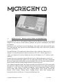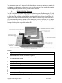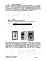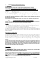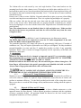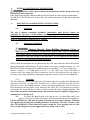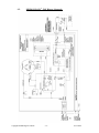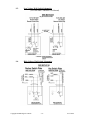
1
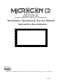
MICROCON® MCD - DOP MICROCON® MCDH - HEPA MICROCON® MCD-HUV - HEPA & UV Germicidal Lamps Installation, Operation & Service Manual Read and Save these Instructions Manufactured by 749 Hope Road, Suite A- Eatontown, NJ 07724 Tel: 800-224-9768, 732-389-8922 Fax: 732-389-8821 03/13/2014 SAFETY INSTRUCTIONS Understand the signal words that are universally used for overall safety. • DANGER • WARNING • CAUTION DANGER identifies the most serious hazards, which will result in severe personal injury or death. WARNING signifies hazards, which could result in personal injury or death. CAUTION is used to identify unsafe practices, which would result in minor personal injury or product and property damage. BEFORE INSTALLATION OR PERFORMING MAINTENANCE OR SERVICE, TURN OFF THE MAIN HIGH VOLTAGE POWER BREAKER TO THE UNIT. ELECTRICAL SHOCK CAN CAUSE INJURY OR DEATH. THERE MAY BE MORE THAN ONE DISCONNECT. READ INSTRUCTION MANUAL THOROUGHLY AND FOLLOW ANY WARNINGS OR CAUTIONS IN THIS MANUAL AND ATTACHED TO THE UNIT BEFORE STARTING INSTALLATION OR MAINTENANCE ACTIVITIES. IMPROPER INSTALLATION, ADJUSTMENT, ALTERATION, SERVICE, MAINTENANCE, OR USE CAN CAUSE FIRE, ELECTRICAL SHOCK, OR OTHER CONDITIONS THAT MAY CAUSE PERSONAL INJURY OR PROPERTY DAMAGE. WEAR SAFETY GLASSES AND WORK GLOVES AND FOLLOW ALL SAFETY LOCAL BUILDING AND ELECTRICAL CODES. CONSULT A QUALIFIED INSTALLER, SERVICE AGENCY OR YOUR SUPPLIER FOR INFORMATION OR ASSISTANCE. NEVER OPERATE THE UNIT WITH THE BLOWER EXHAUST PORTS UNCOVERED OR FILTER ACCESS DOOR OPEN. ALWAYS WAIT UNIT THE BLOWER STOPS SPINNING BEFORE STARTING MAINTENANCE. NEVER EXPOSE EYES OR SKIN TO ULTRAVIOLET LIGHT FROM ANY SOURCE. UV LAMPS MUST BE OFF BEFORE OPENING THE CHASSIS TO PERFORM MAINTENANCE OR SERVICE. PERSONAL INJURY MAY RESULT. THE UV LAMPS CONTAIN SMALL AMOUNTS OF MERCURY. IF A LAMP BREAKS, CLEAN AND DISPOSE THE MATERIAL WITH CARE. 10/08/2013 Table of Contents Section 1. 1.1. 1.2. 1.2.1. Page MICROCON CD ® DESIGN AND TECHNICAL DESCRIPTIONS................................................... 2 MICROCON CD® Filtration................................................................................................................. 3 MICROCON CD® Filters....................................................................................................................... 4 Pre-filter ................................................................................................................................................. 4 1.2.2. High Efficiency Filters ........................................................................................................................... 4 1.2.3. Gas-Phase Filter ..................................................................................................................................... 4 1.3. UV Germicidal Lamps............................................................................................................................ 4 1.4. 1.4.1. Chassis Design ........................................................................................................................................ 5 Dimensions .............................................................................................................................................. 5 1.4.2. Cabinet.................................................................................................................................................... 5 1.4.3. Sound Absorbency:................................................................................................................................. 5 1.4.4. Controls: ................................................................................................................................................. 5 2. 2.1. 2.2. 3. 3.1. 3.2. Sizing....................................................................................................................................................... 6 Required Number of Units ..................................................................................................................... 6 Placement................................................................................................................................................ 6 MICROCON CD® Electrical Functions................................................................................................ 6 MICROCON CD® Blower Motor .......................................................................................................... 7 MICROCON CD® Circuit Breaker ....................................................................................................... 7 3.4.1. MICROCON CD® Power Wall Switch Options .................................................................................... 8 3.4.2. Automatic Controller Options (TCMM,TSCMM,TCMMb) ................................................................ 8 4. 4.1. 4.1.1. 4.1.2. PROCEDURES FOR FILTER RENEWAL.......................................................................................... 9 Filter Replacement ................................................................................................................................. 9 Typical Maintenance Guidelines - Renewal Estimates: ........................................................................ 9 Filters and UV Lamp Maintenance Records ....................................................................................... 10 4.2. 5. 6. 6.1. 6.2. 6.2.1. 6.4. 6.4.1. Disposal of Filters and UV Lamps........................................................................................................ 10 GENERAL MAINTENANCE INFORMATION ............................................................................... 11 ELECTRICAL and MECHANICAL INSTALLATION..................................................................... 11 Unpacking............................................................................................................................................. 11 Mechanical Installation ....................................................................................................................... 11 Mounting............................................................................................................................................... 11 General Electrical Installation Instructions ........................................................................................ 12 Schematics- See the Schematic Section ................................................................................................ 12 6.4.2. Power Requirement – See the Specifications / and Serial No. Label .................................................. 12 6.4.3. Low Voltage Wall Switch - See the Wall switch Installation guide..................................................... 12 6.5. 7. 7.1. 7.2. 8. 8.1. 9. 9.1. 9.2. 9.3. 9.4. 10. Final Inspection Checklist- See APPENDIX C .................................................................................... 12 WARRANTY PROCESS ..................................................................................................................... 12 Making a Warranty Claim................................................................................................................... 12 Shipping Damage Alert ........................................................................................................................ 13 Specification.......................................................................................................................................... 13 Filter Packages ..................................................................................................................................... 13 APPENDIX B SCHEMATICS ........................................................................................................... 14 MICROCON CD® 120V Blower Schematic ....................................................................................... 14 MICROCON CD® 230V Blower Schematic ....................................................................................... 15 Low Voltage Wall Switch Schematics .................................................................................................. 16 High Voltage Wall Switch Schematics ................................................................................................. 16 APPENDIX C - MICROCON CD® INSPECTION CHECKLIST...................................................... 17 Copyright 2014Biological Controls -1- 03/13/2014 1. MICROCON CD ® DESIGN AND TECHNICAL DESCRIPTIONS The MICROCON CD is a self-contained ceiling mounted air-filtration system that is specifically designed for the removal of both airborne pollutants and gaseous contaminants from indoor environments. Particulates, odors, and fumes are drawn through the center grille section, filtered and the cleanair is then dispersed back into the room thru diffusers on either end of the unit to provide a healthier environment. The MICROCON® CD variable speed control delivers 500 to 1000 cfm of filtered air. For example, in a room that measures twenty-by-twenty feet (20’X 20’), with an eight-foot (8’) ceiling, over eighteen (18) room air-changes per hour (one air-change every 3.5 minutes) can be achieved. Exhaust louvers are positioned to channel filtered air in five different directions to provide for good air dispersion and mixing within a room. Air quality improvements will result by maximizing the air movement and creating airflow currents throughout the room. The entire exhaust plenum interior is lined with foam sound-proofing material to reduce noise-levels. The combined component quality and features provided in the MICROCON CD® system makes this industrial air-filtration design a dependable and advanced method of providing air purification solutions to a wide variety of working environments. Typical applications include: Evidence Rooms, Bingo Halls, Bowling Alleys, Bars, Computer Rooms, Copier Rooms, Dental Labs, Kennels, Locker Rooms, Nursing Homes, Smoking Rooms, Photo Labs, Printing Areas, Restaurant/Cafeteria, Sick Rooms, Veterinary and Pathology Labs. Copyright 2014Biological Controls -2- 03/13/2014 The MICROCON CD® can be integrated with industrial gas detectors to continuously monitor the environment for the presence of dangerous gases, provide a means to help remedy the condition, while alerting facility-personnel about a possible harmful situation. 1.1. MICROCON CD® Filtration The MICROCON® CD is a three-stage progressive filtration system. The first stage is a 1" thick synthetic pre-filter designed to contain larger-size airborne particles thereby extending the life of the final-filter. The secondary or final-filter is a hospital-grade, high-efficiency pleated filter-cell capable of removing virtually all of airborne particles in the sub-micron range. Since removal of gas-phase pollutants requires a different capture mechanism - carbon or charcoal, two (2) unique carbon composite-cells are utilized as the last stage which allows for higher adsorbent loading at a lower pressure-drop than comparable carbon cells. Features Progressive filtration system DOP Final Filter 95% efficiency on .3 micro size particles HEPA Final Filter Option 99.97% efficiency on .3 micron particle size UV Germicidal Lamps Option Controls both airborne participate and gas-phase pollutants Mounts flush with ceiling Multidirectional exhaust louvers Baked on white enamel finish Low Voltage (24VDC) Remote Control Options On/Off and Variable-Speed Control Switch Low Voltage Power Relay (for optional Low Voltage control options) Copyright 2014Biological Controls -3- 03/13/2014 1.2. MICROCON CD® Filters The MICROCON CD® houses three types of filters. The first being the pre-filter, followed by a High Efficiency Particulate-filter, and third, carbon cell (gas phase) filters. The frequency of filter renewal will be directly proportional to the “run-time” of the unit and the density and size of particulate and gas in the environment. 1.2.1. Pre-filter The MICROCON CD® unit is equipped with a synthetic pre-filter (24”x24”x1”) to capture the larger size particles in the 1-5 micron range. The timely renewal of the pre-filter will extend the life of the other filters. Due to the nature of the collection process it cannot be cleaned or washed. 1.2.2. High Efficiency Filters Two grades of High Efficiency Filters (18.5”x 23.5”x 4”) are available for use in the unit. • The standard filter is designed to capture particulate in the .3-micron range and has a MERV (Minimum Efficiency Reporting Value) rating of 18. • The optional Hospital-Grade HEPA has capture efficiencies of 99.97% on .3 micron-size particles. The filter choice should be based upon the environmental requirements of the customer. The MICROCON CD® chassis is designed to easily slide and lock either filter into a designated filter compartment. 1.2.3. Gas-Phase Filter Two (2) gas-phase, carbon-cell filters (11.5” x 11.5” x 22.5”) each with 8000 square inches of carbon-filled fabric are designed in an efficient V-bank configuration. The filter contains carbon granulates that adsorb a wide variety of gas-phase pollutants. It is important to keep the carboncells free of particulate for optimal performance. The efficiency of the carbon granules to adsorb odors and gases is diminished if the surfaces become clogged with particulate matter. Therefore, the timely renewal of the pre-filter and High Efficiency filter will maintain the effectiveness of the carbon filters. This Carbon filters easily slide into dedicated filter compartments inside the MICROCON CD® chassis. They are usually changed at the same time the High Efficiency particulate filter or when the HEPA is replaced. 1.3. UV Germicidal Lamps Coupled with the High Efficiency filter-cell, the germicidal effectiveness of the unit is greatly enhanced with the addition of the two (2) optional Ultraviolet (UV) lamps. UV radiation in the 254-nanometer wavelength has proven effective in killing most types of airborne bacteria, viruses and mold spores. The UV lamps provide a "total air quality solution" for most indoor environments. The Germicidal UV lamps are rated for 9000 hours (approximately 12 months) of continuous use. Copyright 2014Biological Controls -4- 03/13/2014 Circumflow® Air Pattern 1.4. Chassis Design Designed for installation in a standard 2’ x 4’ drop ceiling T-bar channel 1.4.1. Dimensions The eyebolt-hole pattern for supporting the unit from the ceiling is 21 ¼” X 38 ¾” (540mm x 984mm). 38.75” (984mm) 21.25” 1.4.2. Cabinet · 20-ga. zinc-plated steel (47 5/8” L x 23”W) · 18-ga. baked white enamel intake grille and filter swing-down Access Door · 2, Removable 18-ga. baked white enamel multi-directional exhaust louvers · 4 heavy duty suspension eye-bolts 1.4.3. Sound Absorbency: · Chassis lined with ½” acoustical absorbing foam sheets 1.4.4. Controls: · On/Off and Variable-Speed Control Switch ·Low Voltage Power- Relay (for Low Voltage remote-control options) Copyright 2014Biological Controls -5- 03/13/2014 EXPLOSION HAZARDS CAN CAUSE SEVERE INJURY OR DEATH • DO NOT INSTALL EQUIPMENT IN ENVIRONMENTS WHERE THE DANGER OF GAS VAPORS OR DUST-EXPLOSION EXISTS. DO NOT INSTALL IN AREAS WHERE EXPLOSION-PROOF ELECTRICAL APPLIANCES ARE REQUIRED OR SPECIFIED. • 2. Sizing To determine the number of Filtration Units required, the suggested method is based on ACH (air-changes per hour). This factor is used to determine the filtration requirements of the area (RV, room volume) to be cleaned. Other elements, such as, the type of contamination present, the concentration levels, the number of room occupants, the speed control, the quality of make-up air, and the room configuration (layout) may add to the overall filtration requirements. 2.1. Required Number of Units 9 Measure Height (H), Width (W), and Length (L) of the Room. 9 Multiply H x W x L = Room Volume (RV) 9 Determine the number of air changes per hour (ACH) (typical 6-10) 9 Determine the operating speed setting of the unit - CFM (cubic feet per minute) 550 – 1000 cfm. 9 Calculate the number of Micron Units as follows: RV x ACH CFM x 60 = # of MICROCON CD® units 2.2. Placement Air is drawn up and exhausted in various directions for thorough cleaning and circulation of the air within the room. Normally, the MICROCON CD® HUV unit will function best when positioned in the ceiling near the center of the room. Where multiple units are required space the units equidistant from one another. When source-capture of pollutants is necessary, units can be placed directly above the contamination source. 3. MICROCON CD® Electrical Functions Before installation begins, always check the Manufacturing Serial Number label (located adjacent to the electrical access panel) for Voltage/Current operating specifications and Filter Information. Copyright 2014Biological Controls -6- 03/13/2014 Sample Serial Number Label NEVER OPERATE THE UNIT WITH THE BLOWER EXHAUST LOUVERS UNCOVERED OR THE FILTER ACCESS DOOR OPEN. ALWAYS WAIT 5 MINUTES AFTER REMOVING POWER TO ALLOW THE HEAVY IMPELLER TO STOP SPINNING. NEVER USE A HAND OR TOOL TO STOP THE SPINNING IMPELLER. 3.1. MICROCON CD® Blower Motor The MICROCON CD® unit contains a reverse-curve, direct-drive, blower with permanently lubricated ball-bearings. The motor is thermally protected with an internal automatic-reset thermal switch. In the event the motor overheats, it will automatically shut-down. However, once the heat dissipates, the motor will automatically restart. It is, therefore always necessary to shut off power to the unit before performing any maintenance or service. 3.2. MICROCON CD® Circuit Breaker A resettable Circuit Breaker (5 amps @ 120V mounted on the side of the chassis near the power access door. If the breaker opens reset it after a 1-5 minute wait before reactivating the unit. Circuit breaker opens are not normal and usually indicate an electrical problem. Consult an electrician before returning the unit to service. Copyright 2014Biological Controls -7- 03/13/2014 3.3. Power Control Options Although MICROCON CD® filtration systems may be activated manually by way of the internal speed control switch, it may be wired to turn-on via and high voltage wall switch, or permanently hard-wired to run 24/7. Installations may also include filtration units equipped with an optional low voltage power-relay control circuit. The option allows the MICROCON to be turned on and off from remote low-voltage wall-switches various automatic low-voltage controllers, or daytimers. See the switch examples and wiring options in the Schematic Section. Automatic Controllers may activate MICROCON CD® filtration units via Gas-detectors, room lights, or room-occupied detectors, etc. 3.3.1. Internal 24VDC Power Module An internally mounted 24VDC @.8A power module or Wall Plug mounted power modules (optional) are available to power various low voltage control options. See Schematic section. 3.4. Controls • On/Off and Variable-Speed Control Switch • Optional Low Voltage Power- Relay (for Low Voltage control options) • • • 3.4.1. MICROCON CD® Power Wall Switch Options Rocker Switch Plates, High Voltage or Low Voltage Plates equipped with Key Switch Plates only (HV or LV) Key Switch Plates equipped with Hour Meter and or Power Indicator LED (Low V only) Examples of some Wall Switch Options Single or multiple MICROCON CD® units may be powered on and off via an optional wall mounted switch. The low voltage Wall Switch is mounted on a standard stainless steel switch plate cover. The plate is equipped with a Keyed-Switch to activate the system, a green LED to indicate that power has been directed to the filtration unit (s), and an optional hour-meter to help maintain filter records. The circuit is powered via a small 24VDC wall-plug power module or an optional 24VDC power module mounted inside of the filtration unit chassis. See Schematics Section for wiring options. 3.4.2. Automatic Controller Options (TCMM,TSCMM,TCMMb) There are various Automatic low-voltage controllers available to activate the Micocon CD units either directly or in parallel. The controllers are usually associated with larger Air Filtration Units that may be used elsewhere within a facility. It is common for one or more MICROCON CD® units to be connected to other facility control circuits. See the Controller Manuals or the distributor for more information. Copyright 2014Biological Controls -8- 03/13/2014 4. PROCEDURES FOR FILTER RENEWAL NEVER OPERATE THE UNIT WITH THE BLOWER EXHAUST PORTS UNCOVERED ALWAYS WAIT 5 MINUTES AFTER REMOVING POWER TO ALLOW THE SPINNING IMPELLER TO STOP BEFORE OPENING THE FILTER DOOR. 4.1. Filter Replacement The filters housed in this equipment are high capacity cells that are selected specifically to work with the MICROCON CD® blower motor. Altering the combination may result in premature maintenance procedures. Filters, other than supplied by the manufacturer, will void both the unit and individual component manufacturer’s warranty. Contact a Factory Distributor for approved filter and part replacements. Record all filter/UV lamp maintenance on the “filter change label” inside the swing-down door. 4.1.1. Typical Maintenance Guidelines - Renewal Estimates: Estimates are based the amount of use and concentrations of pollutants in typical environments. Individual experiences may vary based on actual environmental conditions. Pre-filter Every three (3) months (General use in Cafeterias, bingo halls, smoking areas, bars, etc.) Four-Five (4-5) months (Office, Commercial environments) Every six (6) months (Cleaner environments-Hospital, professional offices, etc.) To replace the filter unlatch two black swell-latches on the face of the center grille swing-down door. Have a large plastic bag ready to receive it. Slide the filter into the bag, seal the bag and dispose of properly. High Efficiency or HEPA Filter Every 12-18 months To replace the filter unlatch two black swell-latches on the face of the center grille swing-down door. Have a large plastic bag ready to receive the loose fitting pre-filter. Slide the pre-filter into the bag. Swing the pivotal-latch lever to the right to release the larger filter. Slide it slightly forward and remove it at an angle. Place the filter into the plastic bag, seal it, and dispose of properly. The new filter fitted into the chassis in the reverse order. Note that it is slid under the small lip (at an angle) in the rear-section of the filter compartment. Be careful not to damage either side of the delicate filter-face when handling. Once properly seated and level with the compartment, secure the pivotal-latch to hold the filter securely in place. Replace the pre-filter and close the swingdown door (grille) using the two black swell-latches. Carbon Cells: Every 12-18 months THE CARBON FILTERS WEIGH APROX 18 LBS EACH. USE CAUTION WHEN RELEASING THESE FILTERS FROM THE CEILING MOUNTS. . Remove the white exhaust louvers by spinning (counterclockwise) the two (2) silver knurled Panel Fasteners found on each cover. Note that the exhaust louvers are not designed to swingdown. When the fasteners are loose gently slide the cover away from the unit and parallel to the ceiling (approx. 1 1/2”) to release them from the mounting bracket-tabs. Copyright 2014Biological Controls -9- 03/13/2014 The Carbon-cells are each secured by two steel angle brackets. These same brackets are the mounting base for the white exhaust covers. The brackets are held in place with four (4) #8 x ½” hex-head sheet metal screws. Note the position of the brackets before removing them so they will be returned to the same locations during reassembly. Use a ¼” hex nut-driver to remove and later reattach the screws. Remove one (1) filter at a time. Hold the 18-pound carbon filter in place to prevent it from falling out while removing the screws and brackets. Place it in a plastic bag and dispose of it properly. Slide new carbon cells into the unit and secure them with the angle brackets and sheet metal screws in the reverse order. When both sides are properly fastened, reattach the two exhaust louvers by aligning the cover slots with the bracket tabs. Align and screw-in knurled head captive panel fasteners. Note: The exhaust louvers are not identical; there is a left and right cover. Make sure that the slots in the louvers are positioned such that air will be directed away from the center swing-down door. UV Germicidal Lamps: Approximately every 9000 hrs (1 year) of continuous use. (see Hour-meter option) The HEPA filter needs to be removed to access the UV bulb compartment of the unit. Follow the HEPA removal instructions above. The germicidal ultraviolet (UV) lamps will operate for approximately 9000 hours (12 months of continuous use). They will require replacement even if they are still lighted. The lamp irradiation potential diminishes over time and after 12 months they provide very little, if any, germicidal irradiation. When a unit is started and stopped frequently, the life expectancy of the bulbs will diminish at a faster pace. Whenever the lamps need to be changed or inspected, special UV eye protection goggles that encapsulate the eyes must be worn. DO NOT LOOK DIRECTLY AT THE BULBS AND DO NOT EXPOSE BARE SKIN TO THE UV LIGHT. Handle the bulbs on the metal ends only. Do not touch the glass without clean gloves. Oil from fingers will deteriorate the special quartz-glass and diminish the bulb service-life. Always remove finger prints and debris with a soft clean cloth. . THE UV LAMPS CONTAIN SMALL AMOUNTS OF MERCURY. IF A LAMP BREAKS, CLEAN AND DISPOSE THE MATERIAL WITH CARE. 4.1.2. Filters and UV Lamp Maintenance Records Maintain accurate filter maintenance records to help determine how frequently the pre-filters as well as the other two filters are replaced. Proper maintenance assures that the air cleaner will perform at maximum efficiency. Use the label provided on the inside of the swing-down center filter access-door to record the filter change activity and hour-meter readings when the option is equipped. 4.2. Disposal of Filters and UV Lamps Differing State and local codes make it is impossible to draw a blanket statement as to the approved means for filter disposal. Follow disposal procedures consistent with the regulations covering a particular facility. All questions should be directed to the local county wastemanagement authorities or EPA for guidance. Copyright 2014Biological Controls - 10 - 03/13/2014 5. GENERAL MAINTENANCE INFORMATION Always remove power during any maintenance routine. Keep water away from all electrical connections. Other than the normal filter changes outlined in this document, the unit requires no maintenance. The MICROCON CD® blower is a direct drive unit with bearing that are sealed and permanently lubricated. 6. ELECTRICAL and MECHANICAL INSTALLATION 6.1. Unpacking The unit is shipped completely assembled. Immediately upon delivery inspect the packaging for any signs of visual damage and inspect again when the unit is unpacked. Failure to identify damage to the unit can disqualify freight claims with the carrier. The carrier is responsible for damage due to shipping. 6.2. Mechanical Installation Support Directly From Building Structure. Obtain an approved fixture attachment design before proceeding with the installation. The ceiling support system of the building must be checked to assure that it is sufficient to carry the weight of the hardware. Do not support the unit directly with the T-bar suspended ceiling hardware. Always check the installation area for obstructions above the space where the units will be placed. Obstructions might include ducting, electrical conduit, water pipes, sprinkler hardware, etc. The MICROCON CD® is designed to lie within the space of a standard 2’ x 4’ Tab’s ceiling panel. Remove a single 2’ x 4’ ceiling panel or two 2’ x 2’ tiles. Make sure to have 20 inches of clearance above the ceiling tiles. Keep in mind that access to the unit from the side panels is necessary (only during installation) requiring the temporary removal of several surrounding tiles. 6.2.1. Mounting The T-bar hardware used for the ceiling tiles itself cannot support the weight of the filtration unit. Galvanized steel-wire (12 gauge min.), threaded rod, or chain is connected from the four eyebolts on the unit to the building structure. Connect the supporting hardware to the four (4) eyebolts mounted on the top surface of the Mircocon unit. Allow the T-bar hardware to provide a seal between the room and the area above it and to provide the proper hanging alignment. The four facility mechanical attachment points and hardware must be capable of supporting a minimum load of 100 lbs each. 6.3. To reduce the initial weight of the unit the two (2) carbon-filters and covers (aprox. 21 lbs each or 42lbs total) may be removed and replaced after the installation. Lift the MICROCON CD® unit and guide it through the T-bar panel opening. Maintain and support the unit until the mounting-hardware is attached to the four eye-bolts of the unit. The MICROCON CD® should sit securely within the T-bar opening with all of the unit’s weight being borne by the support hardware (chain, rod, or wire). Copyright 2014Biological Controls - 11 - 03/13/2014 6.4. General Electrical Installation Instructions Turn off power at the facility Main fuse or circuit breaker-panel before proceeding with wiring or installation activities. All electrical installation and maintenance must be performed by qualified individuals and in accordance with the National Electrical Code. ANSI/NFPA 70-1999 and local codes. Precede with the Installation Electrical Connections only after the unit is mounted in the ceiling. 6.4.1. Schematics- See the Schematic Section 6.4.2. Power Requirement – See the Specifications / and Serial No. Label 6.4.3. Low Voltage Wall Switch - See the Wall switch Installation guide. 6.5. Final Inspection Checklist- See APPENDIX C After an installation or service, use the Final Inspection Checklist to help check that the items listed have been addressed. 7. WARRANTY PROCESS Limited Warranty Biological Controls warrants the following to be free of defects in workmanship and materials during normal use and service for a period of one year (12) months: the blower motor, Chassis sheet-metal parts (not including filters or UV Lamps), and both High and Low Voltage hardware and internal wiring from the date of purchase by the original end user. If at anytime during the warranty period the product is defective or malfunctions, Biological Controls or its dealer or distributor, from whom the product was purchased, shall at the option of Biological Controls replace or repair the defective part or component. This warranty does not cover removal or installation costs. This warranty shall not apply if it is shown that the defect or malfunction was caused by damage due to shipment, improper electrical connections, or improper use or abuse of the product. The sole responsibility of Biological Controls shall be to repair or replace the product within the terms stated above. Biological Controls shall not be liable for any loss or damage of any kind, including any incidental or consequential damages resulting, directly or indirectly, from any breach of warranty, expressed or implied, or any other failure of this product. (Some states do not allow the exclusion or limitation of incidental or consequential damages, so this limitation may not apply to you.) The warranties set forth are exclusive and Biological Controls expressly disclaims all other warranties, whether written or oral, implied or statutory, including but not limited to any warranties of merchantability, workmanship, or fitness for a particular use. In our continuing effort to produce the highest quality products, we reserve the right to change or alter product specifications and materials without notice. This warranty gives you specific legal rights and you may have other rights, which vary, from state to state. 7.1. Making a Warranty Claim To make a warranty claim or if you have questions about the warranty policy, contact your local MICROCON CD® distributor from whom the product was purchased. NOTE: Do not return any products or components directly to the factory without a factory issued “Return Merchandise Authorization (RMA) number” issued by the Biological Controls Customer Service Department. Any products returned without the issuance of the RMA number will be refused and returned to sender. Copyright 2014Biological Controls - 12 - 03/13/2014 7.2. Shipping Damage Alert Immediately upon delivery inspect the packaging for any signs of visual damage and inspect again when the unit is unpacked. Failure to identify damage to the unit at the delivery-time can disqualify freight claims with the carrier. For questions related to this warranty call or write: Manufacturer: BIOLOGICAL CONTROLS 749 Hope Road Suite A Eatontown, NJ 07724 TEL: 800-224-9768 FAX: 732-389-8821 WEB SITE: www.biologicalcontrols.com 8. Sales Distributor: Specification Weight MICROCON CD® - 125 lbs. total weight ( All Filters and Chassis ) Air Delivery • Variable speed 450 cfm to 800 cfm (27,000 to 48,000 cubic feet per hour) Power MICROCON CD®: Input Voltage- 120VAC@ 50/60Hz, 1Phase 2.4A max. ,typical 240 Watts Or Input Voltage- 230VAC@50/60Hz, 1Phase 1.05A max. ,typical 240 Watts UV (optional) 100-250VAC@50/60Hz, Typ.80Watts Low Voltage Power-Relay Control (optional) Typical (24VDC @ 50ma. max) External Power Mod or Internal Power Module (Optional)100-250VAC Input to Module – Output 24VDC Typ. 2 Watts max Check available space above the ceiling (min 20”) Swing down door requires 24” clearance Clearances Dimensions (W) 23.625” (L) 47.625” (D) 18.5”-(20”eye-bolts) Eye-bolt pattern - 21 ¼” X 38 ¾” (540mm x 984mm) Agency Approvals Designed to Pending ETL - USA and Canada (UL507 and CSA C22.2) requirements 8.1. Filter Packages BIOLOGIC FILTERS DESCRIPTION First Stage Filter (prefilter) Second Stage Filter (High efficiency cell) 95% MCDPF-002 20 x 23.5 x 1” – 35% synthetic polyester pad MCDDF-002 Third Stage (gas phase) MCDCF-002 Second Stage Filter Optional (HEPA) 99.7% MCDHF-99 HEPA 19.5 x 23.5 x 4” – Hospital Grade highefficiency 95%, micro-glass media cell 2ea. - 12 x 23.5 x 12” – Dry process carbon composite cells 19.5 x 23.5 x 4” H EPA Filter (99.97% at .3 microns) 2ea. 25W G25T* Germicidal UV Lamps 2-UV Germicidal Lamps MCDUV-002 (optional) Copyright 2014Biological Controls - 13 - 03/13/2014 9. APPENDIX B SCHEMATICS 9.1. MICROCON CD® 120V Blower Schematic Copyright 2014Biological Controls - 14 - 03/13/2014 9.2. MICROCON CD® 230V Blower Schematic Copyright 2014Biological Controls - 15 - 03/13/2014 9.3. Low Voltage Wall Switch Schematics (See Wall Plate Controller User Manual) 9.4. High Voltage Wall Switch Schematics Copyright 2014Biological Controls - 16 - 03/13/2014 . 10. APPENDIX C - MICROCON CD® INSPECTION CHECKLIST PRIOR TO PLACING UNITS INTO SERVICE Is the unit securely fastened to the Building Support Structure and not on the suspended ceiling T-bar hardware? Is the unit level, side to side, back to front? Are all filters properly installed and placed in the correct position? Has the installation date been recorded on filter change label? Is power connected to units and optional power control cables connected? Has the cover on the unit’s junction box been reattached? Is the filter access covers or door securely closed? Is the speed control power switch “on” for blower operation? Are optional remote-control timers and wall switch installed? WHEN POWER IS TURNED-ON, CHECK THE FOLLOWING: Blower is running smoothly. Adjust the speed control dial. Copyright 2014Biological Controls - 17 - 03/13/2014