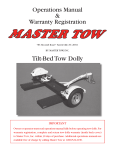
1
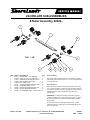
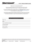
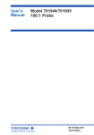
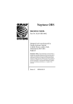
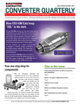
® 2X4 Bundle Document Reference How to read your Service Manual: To identify the model of your trailer please refer to the VIN decal located on the inside of the left side frame at the front of the trailer. This Bundle Document Reference Sheet refers to the model identification of your trailer and the components that make up that particular trailer. Refer to the chart below: Listed are the various components with document numbers listed. The document number is located in the lower right-hand corner of each service manual sheet. When referencing the different components of your trailer, please refer to the document number and revision entry with date. When contacting your dealer for service, please refer to the document numbers and revision entry dates. SLR31BS FRAME DOC# ROLLER SUBASSY DOC# CHASSIS DOC# WINCH ASSY DOC# 0002803 0002813 0002812 0002814 Color Coating Reference NOTE: ShoreLand’r offers their product line in either galvanized or painted finish. When ordering parts it is important that you specify the finish or color you have on your product. The five digit number along with a two digit space _ _, notes the parts which can be purchased with various finishes. When ordering these items use the five digit prefix and include the following two digit suffix for proper finish. Suffix 00 or G 01 03 or BK 06 or AW Finish / Color Galvanized Arctic White Black Antique White Tongue Weight Adjustment Approximate Tongue Weight for Best Towing. Tongue weight too high, move the axle assembly forward. Tongue weight too low, move the axle assembly backward. Tongue weight should be 5-7% of total gross weight of both boat and trailer combined. Cautions/Warnings The law requires that the white ground wire on the both the tongue wire harness and the vehicle harness be properly grounded to the respective trailer and vehicle frames. Double check all nuts and bolts ---- tighten before towing. Made in the USA Midwest Industries, Inc. Ida Grove, IA 51445 (800)859-3028 www.shorelandr.com 0002796 REV A - 10/19/00 ® REF# 1 2 3 4 5 6 7 8 9 10 11 12 13 14 15 16 17 18 19 20 21 22 23 24 25 26 PART# 60047-6046200 60626-60888-61914-62087 64145 65541-65542-65601 65781 66099-66127-0110096 0110114 0110120 0140040 0210130 0210137 0210138 0210220 0240210 0310228 0810126 0810925 0810945 1310040 1310170 SLR24BS/31BS DESCRIPTION QTY ADJ BUNK BRKT ...................................... 2 ADJUSTABLE BUNK CLAMP ................... 2 ROLLERARM 8 ROLLER 2X4 .................. 2 KEEL CRADLE ASSY ................................ 1 ROLLERARM MTG BRKT WMENT ......... 2 PLASTIC SPACER REAR PIVOT ARM .... 2 BRAKELINE ASSY 186" W/COILS .......... 1 TONGUE 3X5X55 ...................................... 1 OUTER HOUSING - UFP ACTUATOR .... 1 BRAKELINE ASSY 56" ............................. 1 ALUM EXT - CENTER PAD RISER 124 ... 2 FRAME WMENT 74 WIDE 178 LONG ..... 1 REAR CROSS WMENT (74 WIDE) .......... 1 HH 1/2-20 X 1-1/2 ...................................... 1 HH 1/2-13 X 4 CS GR5 ............................. 4 HH 1/2-13 X 5 CS GR5 ............................. 1 HH 3/8-16 X 1 CS GR5 ............................. 2 CARR 3/8-16 X 3 3/4 GR5 ........................ 1 CARR 3/8-16 X 5 FULL THREAD GR5 .... 2 CARR 3/8-16 X 5 1/2 FULL GR5 ............. 2 CARR 1/2-13 X 4 1/2 GR5 ........................ 2 CARR 1/2-13 X 3 GR5 .............................. 4 SUB 1/2 X 3 9/16 X 4 1/4 .......................... 2 SCREW SELFTAPPING TYPE B 1/4X1/2 4 SCREW SELFDRILL HWH #10-16 X 3/4 . 2 SCREW SELFDRILL 1/4-14X3/4 ............. 1 LOCKWASHER 1/2 S/T MED ................... 4 WASHER#10 USS FLAT ........................... 2 REF# 27 28 29 30 31 32 33 34 35 36 37 38 39 40 41 42 43 44 45 46 47 48 49 50 PART# 1340030 1340095 1340100 1410109 1440101 1440102 1440159 2220272 3510022 3510030 3510122 3510158 3510538 3510542 3991013 4810501 5110013 5110014 5110045 5110112 5110348 5110347 5110354 5110355 S-3390 S-3391 S-3510 S-3553 DESCRIPTION LOCKWASHER 3/8 S/T MED ................... WASHER USS FLAT 3/8 ........................... WASHER USS FLAT 1/2 ........................... HEX NUT FINISH 3/8-16 .......................... FLANGE LOCKNUT SMALL 3/8-16 .......... FLANGE LOCKNUT SMALL 1/2-13 .......... HEX NUT FINISH 1/2-13 .......................... CHAIN 8/0 MACH CHAIN 37" W/837 ....... GROMMET 7/16IN MOLDED .................. GROMMET 7/8IN MOLDED .................... LIGHT BEZEL - WHITE ............................. PLASTIC DRIVE RIVOT ........................... REAR CROSSMEMBER PAD .................. MOLDED REAR CROSSMEMBER PAD .. ACTUATOR UFP - DISC BRAKE AXLE ... SMALL SHORELANDR DECAL ............... DRY LAUNCH LIGHT ASSY (LEFT) ........ DRY LAUNCH LIGHT ASSY (RIGHT) ...... 3 LIGHT CLUSTER 1994 LEXAN ........... MARINE YELLOW CLEARANCE LIGHT . BO LICENSE PLATE BRACKET .............. HARNESS 5-PRONG FLAT .................... HARNESS FRAME 2X4 LEFT 17FT 2I .. HARNESS FRAME 2X4 RIGHT 17FT 2 . STEP PAD RIGHT 2 1/2 X 7 .................. STEP PAD LEFT 2 1/2 X 7 ..................... TONGUE COVER PLATE ......................... BUNK ASSY 2X6X10" W/BRKT ................ QTY 3 1 3 3 4 12 4 2 1 11 2 4 2 1 1 2 1 1 1 2 1 1 1 1 1 1 1 2 #0002813 #0002814 #0002813 Made in the USA Midwest Industries, Inc. Ida Grove, IA 51445 (800)859-3028 www.shorelandr.com 0002803 REV A - 10/24/00 Final Assembly Instructions Remove the small parts from the frame by cutting the bands. Remove the bolt bag and sort all nuts and bolts by size. Tongue: Remove the tongue assembly from the frame bundle and install into the tongue channel and secure with a 1/2 X 4 hex bolt in the side of the tongue and tongue channel. Secure with a 1/2 flange lock nut. Place the tongue cover over the rear of the tongue and tongue channel and secure with a 1/2 X 1-1/2 hex bolt, 1/2 flat washer and 1/2 hex nut. Tongue Wires: Install the tongue wire harness through the top forward wire hole and exit the rear of the tongue channel on the frame. Install grommets and plug the tongue wire into the frame harness by color. Actuator & Safety Chain: Slide the actuator (Ref.#41) into the actuator housing unit (Ref.#8) and secure with two pins and snap rings provided with the actuator. Secure the actuator-housing unit to the front of the tongue using three-(3) ½ X 4 hex bolts and ½ flange lock nuts. Using a ½ X 5 hex bolt on lower right mounting hole on tongue, secure the safety chain. Place a ½ flat washer on ½ X 5 hex bolt followed by one safety chain and insert into actuator housing unit and tongue. Place the second safety chain on the bolt followed by a ½ flat washer and ½ flange lock nut. Tighten. Brakes: Refer to the brake manual for service and maintenance. Roller Assembly: Refer to Doc# 0002813 for assembly instructions. Keel Roller: Refer to Doc# 0002813 for assembly instructions. ® 2X4 ROLLER SUB ASSEMBLIES 8-Roller Assembly, 60626-- REF# 1 2 3 4 5 6 7 8 9 10 PART# 61913-0210127 1310121 1440100 1540350 S-3184 S-3368 S-3382 S-3383 S-3384 DESCRIPTION ROLLERARM 1720 INBOARD .............. CARR 3/8-24 X 3 W/1 THRD GR8 ........... WASHER USS ALUMINUM FLAT 3/4 ...... HEX LOCKNUT 3/8-24 GRA ..................... BULL RING PLAIN .................................... PLASTIC MOLDED SWIVEL BLOCK ....... INLINE ROLLERPIN 19 1/2 ...................... ROLLER WITH MOLDED HUB 5IN ........ ROLLER BUSHING MOLDED .................. FLAT WASHER 2OD X 1.150ID ALUM ... QTY 1 4 8 4 8 2 4 8 8 8 Roller Assembly: Mount the 8-roller assembly to the rear crossmember in a location that best fits your boat. Secure with 1/2” x 4-1/2” carriage bolts and 1/2” flange lock nuts. Roller Ajustment: Place your boat on the trailer. Determine the spacing on the roller rack. It may be necessary to adjust your roller rack either further in or out from the position you ahve it assembnled. The boat must be adjusted to miss any keel or strake which might be on your particular boat. IMPORTANT: The roller rack should be spaced as far apart as possible for stability. This in most cases will also allow your boat to be as low as possible on the trailer for better tgrailering, loading and unloading. Once the roller racks have been spaced properly for your boat, position the boat on th trailer with the transom flush with the rear of the rear roller rack. Made in the USA Midwest Industries, Inc. Ida Grove, IA 51445 (800)859-3028 www.shorelandr.com 0002813 REV - 7/11/00 4-Roller Keel Cradle Assembly, 60888-- REF# 1 2 3 4 5 6 7 8 9 PART# 60883-6088410 60885-6205210 62108-65528 0140040 1440101 1540350 DESCRIPTION KEEL CRADLE .......................................... KEEL CRADLE ROLLER PIN ................... KEEL GUIDE ROLLER BRACKET ........... KEEL CRADLE ROLLER PIN ................... RISER BRKT KEEL GUIDE ROLLER ...... 8IN KEEL ROLLER .................................... HH 3/8-16 X 1 CS GR5 ............................. FLANGE LOCKNUT SMALL 3/8-16 .......... BULL RING PLAIN .................................... QTY 1 4 2 1 1 4 6 6 10 4-Roller Keel Assembly: Mount the 4-roller keel assembly to the under side of the front crossmember in ear weldments using the keel cradle roller pin (Ref.#4). Secure this assembly using bull rings (Ref.#9). 4-Roller Keel Adjustment: Adjust the front keel roller assembly to the desired position to level the boat. ® CHASSIS 31B REF# 1 2 3 4 5 6 7 8 9 10 11 12 13 14 15 16 17 18 19 20 21 22 23 PART# 4279 62201-6234710 66154-66162-66438-66471 0110170 0140040 0210130 0310170 0310276 0610042 1310035 1310163 1340206 1410229 1440101 1440102 1440259 1440349 1540038 3510122 DESCRIPTION QTY SHIM PAD U BOLT 12GA FRAME .......... 4 FENDER 10IN POLY ............................... 2 BRAKELINE CLIP BRACKET ................... 1 AXLE WMENT (74 WIDE) ......................... 1 SPRING BRKT 10IN SINGLE .................. 2 AXLE ASSY 74 WIDE W/BRAKES ............. 1 BRAKE LINE ASSY 99" ............................. 1 HH 9/16-18 X 3 1/4 CS GR5 ..................... 4 HH 3/8-16 X 1 CS GR5 ............................. 8 CARR 3/8-16 X 3 3/4 GR5 ........................ 1 SUB 1/2" X 2-5/16"X6-1/2 .......................... 4 SUB 1/2 X 2 9/16 X 6 1/2 .......................... 4 SOCKET HEAD SCREW 7/16-20X1-1/4 .. 4 LOCKWASHER 7/16 S/T .......................... 4 WASHER 1.377 OD X .390 ID .................. 8 WASHER 1.5 OD X .765 ID X .186/.206 .. 2 HEX LUGNUT 1/2-20 13/16 OD Z&U ....... 10 FLANGE LOCKNUT SMALL 3/8-16 .......... 9 FLANGE LOCKNUT SMALL 1/2-13 .......... 16 HEX LOCKNUT 9/16-18 GRA ................... 4 HEX NUT SLOTTED PLAIN ..................... 2 COTTER KEY 1/8 X 1 1/2 ......................... 2 LIGHT BEZEL - WHITE ............................. 4 Made in the USA REF# 24 25 26 27 28 29 30 31 32 33 34 35 36 37 38 39 40 41 42 43 44 45 46 PART# 3510132 3510158 4300198 4300199 4410089 4410130 4410246 4410247 4410289 4410290 4410291 4440160 4440170 4510506 4510518 4610048 5110112 5110113 4510511 S-3387 S-3501 S-3207G S-3409G S-3449G DESCRIPTION QTY AXLE PAD 12IN BLK ................................ 1 PLASTIC DRIVE RIVOT ........................... 8 ST215/75R 14C TIRE/GALV DIR RIM ...... 2 ST215/75R 14C TIRE/MSILVER DIR RIM 2 SPINDLE SLEEVE 1 1/4-3/4IN BRG ....... 2 SEAL 1 3/8IN ............................................ 2 SL BEARING PROTECTOR BRA ............ 2 BEARING BUDDY - STAINLESS STEEL . 2 DISC BRAKE CALIPER ASSY - LEFT ..... 1 DISC BRAKE CALIPER ASSY - RIGHT ... 1 HUB/VENTED ROTOR, C.B., ASSY, 13 .. 2 ROLLER BEARING 1 1/16IN .................. 2 ROLLER BEARING 1 3/8IN .................... 2 PLUG ......................................................... 1 HOSE CLIP - 1457-YZ ............................... 1 SPRING 5 LEAF HOOK ........................... 2 MARINE YELLOW CLEARANCE LIGHT . 2 MARINE RED CLEARANCE LIGHT ........ 2 18IN MALE-FEMALE BRAKE HOSE ........ 1 2" PLASTIC CHANNEL BRACKET .......... 1 RUBBER CUP WASHER .......................... 8 SPRING BRKT BUSHING PLATED ZYU . 2 SPRING CLAMP 1/4X1 1/2X4 ZYU ....... 2 SPRING AND AXLE U-BOLT PLATE ........ 2 Midwest Industries, Inc. Ida Grove, IA 51445 (800)859-3028 www.shorelandr.com 0002812 REV A - 12/05/00 Place one of the spring bushings (Ref.#44) into the rear of the spring bracket (Ref.#5) and secure with a 9/16 X 3-1/4 hex bolt (Ref.#8) and 9/16 hex lock nut (Ref.#20). Repeat on the other side. Position the axle (Ref.#4) under the frame, then hook the spring loop around the bushing just installed. Raise the axle assembly up so the front of the springs (Ref.#38) line up with the front spring bracket hole. Insert the other two (2) 9/16 X 3-1/4 hex bolts and 9/16 hex lock nuts. Tighten all nuts and bolts, but do not over tighten. Allow the spring room enough to move. Mount the tires and rim assemblies (Ref.#26) using 80-90 ft. lbs. tongue on lug nuts (Ref.#17) using proper tightening procedures. Refer to the brake manual for service and maintenance. Tire Size & Carrying Capacity Chart Tire Size ST215/75R14 Load Range C Carrying Capacity 1870 lbs. per/tire Refer to the tire side wall for the correct tire pressure. ® Profile 2000 Winch Assembly REF# 1 2 3 4 5 6 7 8 9 10 11 12 13 14 15 16 17 18 19 20 21 22 23 24 25 26 PART# 6081600 60930-6107503 65657-65659-0110064 0110118 0110125 204009 204360 204808 204809 205014 205116 205126 205139 205269 205270 206281 0210102 304731 404868 404872 404878 1340095 1440101 DESCRIPTION QTY WINCH POST SPACER ............................... 1 WINCH POST 7IN ................................... 1 END CAP - BLACK PROFILE 2000 .......... 2 WINCH HOLDER CASE ........................... 1 PROFILE 2000 WINCH CASE ASSY ....... 1 HH 3/8-16 X 5 CS GR5 ............................. 1 HH 1/2-13 X 4 1/2 CS GR5 ....................... 5 HH 1/2-13 X 5 1/2 CS GR5 ....................... 1 SHAFT BUSHING DL1400/2500 .............. 2 SPACER WASHER DL1602 ..................... 1 REEL SPACER DL1700 ........................... 1 HANDLE HUT DL1602 ............................. 1 LOCK NUT DL1400/1700/1802/2500 ....... 1 E-RING DL1602/1700/2500 ....................... 1 HH 3/8-16 X 5 CS GR5 ............................. 1 SPACER WASHER DL1700/1802/2500 .... 1 RATCHET PAWL BOLT 1/4-20 X 5 ........... 1 LOCKNUT 3/8-16 JAM STYLE - WINCH . 1 EXTENSION SPRING DL1400-2500 BLU 1 CARR 3/8-16 X 1 GR5 .............................. 1 DRIVE SHAFT UPPER DL1802 .............. 1 REVERSABLE RATCHET PAWL .............. 1 RACHET SPACER DL1700/2500 ............ 1 RATCHET SLEEVE DL1700/2500 ........... 1 WASHER USS FLAT 3/8 ........................... 1 FLANGE LOCKNUT SMALL 3/8-16 .......... 2 Made in the USA 27 28 29 30 31 32 33 34 35 1440102 2210145 3110237 3110348 3510065 3520011 3520019 LH308 S-3374 FLANGE LOCKNUT SMALL 1/2-13 ........... 6 CHAIN 1/4(7MM)X 10 LINKS .................... 1 WINCH HANDLE DL1802 ........................ 1 WINCH REEL W/STRAP DL1800/1802 ... 1 4" BOW ROLLER - BLACK ....................... 1 PLUG 3/8IN WHITE PLASTIC ................. 4 PLUG 1IN WHITE PLASTIC .................... 2 CUP WASHER .......................................... 2 NYLN WINCH CASE BUSH-3/4ODX4.25 1 Winch Post Assembly: Mount the winch post to the tongue in the desired position and secure with three (3) 1/2 X 4 carriage bolts and 1/2 flange lock nuts. Mount the winch handle on the winch shaft using the special hardware provided with the winch. Winch Post Adjustment: Before adjusting the winch post check to see that the transom of the boat is flush with the rear of bunks. Slide the winch post into position. NOTE: The winch holder (upper portion) must be positioned just above the bow eye. Run the winch strap over the upper nylon bushing in the winch case and secure to the bow eye. Tighten all bolts on the winch post. Slip the bow eye safety chain into the bow eye. Adjustment is complete. Midwest Industries, Inc. Ida Grove, IA 51445 (800)859-3028 www.shorelandr.com 0002814 REV - 7/11/00