1
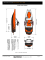
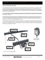
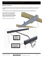
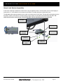
SHORESTATIONLAKEFRONTSYSTEMS Installation & Service Manual SHORE STATION® FLEX POWER® HYDRAULIC BOAT H OUSE LIFT Patent Pending Models: SSBH408HS, SSBH608HS, SSBH808HS Document Number: 0004454 Page 1 SHORESTATIONLAKEFRONTSYSTEMS Table of Contents Click on the section title to jump to the section: Safety Definitions ............................................................ 3 Safety Instructions ........................................................... 3 Introduction...................................................................... 5 System Overview ............................................................ 6 Hydraulic Power Unit ....................................................... 7 Lift Tubes......................................................................... 8 Lift Platform ..................................................................... 9 The FlexPower® System .............................................. 10 Accessories ................................................................... 10 Components & Specifications ....................................... 11 Boat House Lift Systems ............................................... 11 Power Source Kits ......................................................... 13 Battery Requirements ................................................... 13 Platforms ....................................................................... 14 Hanger Kits.................................................................... 15 Bunk Kits ....................................................................... 18 Pre-Installation .............................................................. 20 Preparation .................................................................... 21 Tools Required .............................................................. 21 Survey the Boat ............................................................. 21 Hose and Harness Routing ........................................... 24 Installation Instructions.................................................. 25 Lift Tube Installation Instructions................................... 25 Platform Installation Instructions ................................... 37 Assembly Inspection Checklist...................................... 40 Care and Maintenance .................................................. 41 Cable and Chain Inspection .......................................... 41 Batteries and Electrical ................................................. 41 Pulley Sheaves ............................................................. 41 Hydraulic Fluid............................................................... 41 Oil Change Procedure ................................................... 42 System Bleeding ........................................................... 43 Troubleshooting ............................................................ 44 Emergency Operation ................................................... 47 15 Year Limited Warranty ............................................. 48 Document Number: 0004454 Page 2 SHORESTATIONLAKEFRONTSYSTEMS WARNING DO NOT INSTALL OR OPERATE A LIFT WITHOUT STUDYING THIS MANUAL AND INFORMATION ON LABELS INCLUDED WITH THE LIFT. FAILURE TO DO SO CAN LEAD TO IMPROPER INSTALLATION RESULTING IN SERIOUS PERSONAL INJURY AND/OR PRODUCT DAMAGE. IF YOU HAVE FURTHER QUESTIONS AFTER REVIEWING THIS INFORMATION, CONTACT A SHORESTATION REPRESENTATIVE AT (800) 859-3028. Safety Definitions Safety messages are presented throughout this document and labels affixed to the product. The messages alert you to potential hazards to you and/or property. The signal words DANGER, WARNING, and CAUTION are preceded by an alert symbol follows: and communicate the severity of potential hazard. The severity of each type of message is defined as DANGER indicates a hazardous situation which, if not avoided, will result in death or serious injury. WARNING indicates a hazardous situation which, if not avoided, could result in death or serious injury. CAUTION, used with the safety alert symbol, indicates a hazardous situation which, if not avoided, could result in minor or moderate injury. Safety Instructions Working with electrical equipment and installations over the water present many potential hazards to the installer. Every installation presents unique conditions that the installer should evaluate before installing or servicing the equipment. The following instructions must be followed, but may not encompass all potential hazards: WARNING Never use this equipment to lift people. People must exit the boat prior to lifting it out of the water. Never use this equipment to lift overhead. Install the platform so it remains at or below the dock level. This equipment is designed to lift boats. Never use it to lift other items. Do not allow children to operate or play on the equipment. Do not install or use the lift if there are any signs of damage. The wireless control system should only be operated if the operator has clear vision of the lift equipment and its surrounding location. Never install or work on the equipment without first verifying that the A/C power supply (if present) is protected by a functioning Ground Fault Circuit Interrupt (GFCI) in accordance with National Electric Code section 210.8 and any additional local code requirements. Document Number: 0004454 Page 3 SHORESTATIONLAKEFRONTSYSTEMS Review all operating instructions with the user(s) before allowing them to operate the lift. Disable the lift by disconnecting the battery power to the motor until you have an opportunity to train the user. Disconnect all A/C power from the dock before installing or working on the equipment. Do not exceed the recommended capacity of the equipment. Do not modify the equipment unless you have received direct written approval from the manufacturer (ShoreStation). Remove any metallic objects from your person before working with DC or AC electrical components. Always wear proper personal protective equipment such as safety glasses, gloves, hardhats, and clothing. Installation may require entering the water. Never enter the water without a proper personal floatation device. Disconnect any power to the lift and dock before entering the water. Never work alone and observe safe lifting practices such as team lifting and proper lifting posture. DANGER DO NOT GO NEAR LEAKS! High pressure oil easily punctures skin causing serious injury, gangrene or death. If injured, seek emergency medical help. Immediate surgery is required to remove oil. Do not use finger or skin to check for leaks. Lower load or relieve hydraulic pressure before loosening fittings. Document Number: 0004454 Page 4 SHORESTATIONLAKEFRONTSYSTEMS Introduction ShoreStation’s FlexPower® Hydraulic system is the most safe & reliable boat lift on the market. The intention of this document is to provide qualified installers the information needed to ensure a safe and satisfying experience for the end-user. The end result of this experience will be repeat business for you! The FlexPower® Hydraulic Boat Lift has key features that add value for the owner and end-user: Speed - The hydraulic system can lift 8’ in less than one minute. This is 4-5 times faster than gear-plate systems on the market. This speed is accomplished without requiring large modifications to existing electrical circuits with the unique FlexPower® System. Cable Life – There is no winch, so the cable is not being wound. The most common cause of cable failure is fatigue caused by winching and wear caused by the cable rubbing together during winching. With the ShoreStation FlexPower® Hydraulic system, the cables are pulled by hydraulic cylinders. Large cable sheaves ensure that very little (if any) fatigue will occur. This statement is backed by our 15 year warranty that includes cables. FlexPower® - This unique power system provides maximum power to the lift without costly electrical installations or modifications. The owner can use an existing 120V, 50 or 60 Hz, A/C circuits to supply the system or opt for the 20W, 24V DC solar panel. The FlexPower® system has its own list of advantages: o Maximum motor life – DC motors can deliver instantaneous torque without causing nuisance tripping of breakers and are not prone to long term damaged caused by low voltage A/C conditions common in the long electrical runs that feed boat lift installations. o Safety – A/C Power can be eliminated from the dock when using the solar option. DC power is safe and reliable. o Power when you need it – The battery bank can supply over 10 full lifts with one charge giving you power even if the supply is disrupted. Simple Operation - Hydraulics can deliver power over large distances through hydraulic hoses. This eliminates the requirement to have multiple motors and eliminates the need to run electric power under water. The unique FlexPower® Hydraulic pump mechanically ties two hydraulic pumps to one motor, forcing equal volume to each side of the lift. This forces the system to stay level even if the load is not balanced on the lift, eliminating the need for the user to balance multiple motors. Document Number: 0004454 Page 5 SHORESTATIONLAKEFRONTSYSTEMS System Overview This section provides insight into how the FlexPower® Hydraulic system works. The FlexPower® Hydraulic Boat House Lift consists of the components shown in Figure 1. We will discuss each component’s role in the operation of the boat lift. Hanger Brackets Pump-side lift tube Secondary side lift tube Hydraulic Power Unit Adjustable Extension Chain Support Bunks Lift Platform Figure 1 – The FlexPower® Hydraulic boat House Lift Document Number: 0004454 Page 6 SHORESTATIONLAKEFRONTSYSTEMS Hydraulic Power Unit Power Unit Motor The hydraulic power unit (Figure 2) is the ‘heartbeat’ of the system. The power unit contains two hydraulic pumps connected to a single motor shaft. This mechanical connection forces the same volume of hydraulic fluid to each lift tube and keeps the each side synchronized. A wireless controller or wired dock-side switch activates the motor solenoid and initiates the fluid flow. The fluid is delivered to each lift tube through hoses (Figure 3). The pressure from each set of hoses opens a built-in counterbalance valve on each lift cylinder and moves the hydraulic cylinders inside each tube. Notice: The ShoreStation FlexPower® system comes with hose lengths and brackets to mount the power unit and batteries to the pump-side lift tube. Extension hoses are available if your installation requires the power unit to be mounted in a different location. Reservoir Controller Tandem Pumps Figure 2 – Hydraulic Power Unit Lift Tube Hydraulic Hose Hydraulic Hose Figure 3 - Fluid Power Delivery Document Number: 0004454 Page 7 SHORESTATIONLAKEFRONTSYSTEMS Lift Tubes The two lift tubes create lifting action by retracting the lift cylinder (Figure 4). The rod of each lift cylinder pulls a pulley block and creates cable movement. This lifting principle creates a few key advantages: The lift cylinder retracts to lift the boat. This causes the rod surface to be retracted into the cylinder when the boat is lifted. The polished rod surface is protected from exposure to the harsh marine environment. Pulling the cables instead of winching dramatically increases the lifespan of the cables. This in combination with the stainless material used ensures that the cable life will match the life of the lift. The system cannot be over-winched or back-wound, which is a common problem for plate-gear and winch type systems. If the system is run too far, the hydraulic cylinders will bottom-out and the hydraulic flow is relieved through the pump. The lift tubes ship from the ShoreStation factory with the cables pre-strung. There are no cables for the installer to modify or install in the field. This makes installation of the lift tubes very simple. Each lift cylinder has a counter-balance valve built in. This valve ‘locks’ the fluid flow when there is no pressure. This ensures that the hydraulics cannot move, even if the hydraulic hoses are cut. The cylinders can only move if the system pressure has opened the counter-balance. The lift motion is stopped by a limit switch on the end of each lift tube. This limit switch will stop the lift when both lift tubes have hit the switch lever. This will correct any out-of-level and ensure the system shuts down at the end of the lift. Pulley block Lift Cylinder Limit Switch Long Lift Cable Figure 4 - The lift tube components Document Number: 0004454 Short Lift Cable Page 8 SHORESTATIONLAKEFRONTSYSTEMS Lift Platform The lift platform is specifically designed for use with the FlexPower® Hydraulic Lift. The aluminum construction, aluminum brackets, and stainless fasteners ensure the components will withstand the harsh marine environment. The unique Ultra Bunks are made from aluminum and plastic and eliminates the need for any wood on the lift platform for boat support. This bunk system is specifically designed to conform to the shape of the boat hull. The system is also completely adjustable to match the width of the boat house. WARNING NEVER USE THIS SYSTEM WITH A SLINGSTYLE LIFT. The stainless steel chain extension creates the adjustment for the platform distance. The distance from the lift tubes to the platform will vary in every boat and boat lift installation. The chains provide 4’ of adjustment for this variation. Chain Extensions Ultra Bunks Platform Cross Members Platform Spacer Figure 5 - Lift Platform Components Document Number: 0004454 Page 9 SHORESTATIONLAKEFRONTSYSTEMS The FlexPower® System FlexPower® was developed by ShoreStation and is the result of providing hydraulic and winch driven boat lifts to the marine market for over 15 years. The design of this system is the result of this experience and is the fastest, most robust lift system on the market. FlexPower®, by design, is immune to many of the conditions that exist in the harsh marine environment. The FlexPower® Hydraulic system consists of a 24V DC hydraulic power unit, battery bank, power supply, and controller. The system can be powered by either A/C power supply or a 20W, 24V solar panel. This flexibility in power supply eliminates costly changes to existing A/C circuits or it can totally eliminate the need to provide A/C power on the dock. The system’s speed is the result of the battery’s ability to deliver large bursts of power to the power unit without creating a large demand on the power supply. Traditional A/C systems simply cannot reliably produce this speed without large, expensive A/C circuits. The A/C supply option uses the existing dock circuit to power a Battery Tender that constantly monitors the battery state and applies the appropriate charging method. This system can supply full power even if the A/C circuit voltage drops to 90V A/C. The A/C circuit is buffered from the surge of power required by the hydraulic system and reduces nuisance tripping of breakers and GFCIs caused by the power demands of a boat lift. The solar option supplies power to the battery via 20W solar panel. This panel will easily restore power to the lift using the sun’s energy. It will typically take about 1/3 of a day (assuming full sun) to replenish the power used to do 1 full lift (8’). The lift battery bank stores enough power to perform at least 10 full lifts. Solar is a great option for most users who use the lift heavily on the weekend, but sparingly during the week. Regardless of the power supply, the FlexPower® system will provide safe, reliable operation in conditions where traditional A/C systems fail. When the storms knock out the dock circuit, the FlexPower® system will still operate. Accessories Accessories are available from ShoreStation. These components are not covered in this document, but include the following: Load guide poles Lights Pontoon boat support systems Bow stops Canopies Contact ShoreStation for information about the accessories available for this lift. Document Number: 0004454 Page 10 SHORESTATIONLAKEFRONTSYSTEMS Components & Specifications ShoreStation provides a number of standard components to create the lift solution. The following components are used in combination to create a complete lift. In some cases, additional hardware and/or components are required. Contact ShoreStation if you require information on additional components. Boat House Lift Systems Model Capacity Weight Vertical Lift Travel System Voltage Construction Control Supply Power Options Included Equipment Hydraulic Fluid Document Number: 0004454 SSBH408HS SSBH608HS SSBH808HS 4000 lbs. (1814 kg) 6000 lbs. (2722 kg) 8000 lbs. (3629 kg) 562 lbs. (255 kg) 570 lbs. (259 kg) 580 lbs. (263 kg) 8 ft. (2.4 m) 24V DC Aluminum enclosure, stainless & brass fasteners, Nylon sheaves w/GARMAX® Bearings FlexPower® Wireless Control with 2 transmitters, one wired dock-side switch. 120V AC 50/60 Hz Battery Tender Plus 20W 24V Solar Panel Lift tubes, battery boxes and hanger, hydraulic power unit, controller, 2 wireless key fobs, wired rocker switch box, pump side and secondary side hose sets, Jax Marine-Guard Blue Series AW46, ISO 22, 32, 46, 68, 100 Meets U.S. Coast Guard Static Sheen Test requirements (as defined in 40 CFR Part 435, Subpart A, Appendix 1) & U.S. EPA testing of Pimephales promelas (fathead minnow), Oncorhynchus mykiss (rainbow trout) and Mysidopsis bahia (shrimp) see EPA EPA-821-R02-012. Page 11 SHORESTATIONLAKEFRONTSYSTEMS Figure 6 - SSBH408HS, SSBH608HS, and SSBH808HS lift dimensions (inches [mm]) Document Number: 0004454 Page 12 SHORESTATIONLAKEFRONTSYSTEMS Power Source Kits A/C Battery Tender Part Number Input Voltage & Frequency Output Current Output Voltage A/C Plug Style Charging Method Features 5310286 120 VAC, 50/60 Hz 2.5 Amps 24V DC NEMA 5-15 4-Step (Initialization, Bulk, Absorption, & Float Waterproof Short Circuit & Reverse polarity protected Provides full charge current down to 90VAC DANGER RISK OF ELECTRIC SHOCK. CONNECT ONLY TO A GROUNDED TYPE RECEPTACLE PROTECTED BY A GROUND-FAULT INTERRUPTER (GFCI) AS REQUIRED BY NATIONAL ELECTRIC CODE Article 210.8 Section C. Solar Panel Part Number Rated Max Power (Pmax) Current at Pmax (Imp) Voltage at Pmax(Vmp) Short Circuit Current (Isc) Open-Circuit Voltage (Voc) Harness Length HA0135 20W .6A 33.0V .65A 40.0V 25 ft. [7.6m] Battery Requirements The FlexPower® Hydraulic system requires 24V DC power. This is created by connecting two 12V DC batteries in series. The FlexPower® system includes the require battery cables and harnesses to connect two standard marine deep-cycle batteries together. The system does not include the batteries. The following specifications are recommended for the battery selection: Always use two of the same types of batteries on the system Size Type Marine Cranking Amps Reserve Capacity Document Number: 0004454 Group 24 or 27 Marine Deep Cycle 625 180 @ 25A Page 13 SHORESTATIONLAKEFRONTSYSTEMS Platforms Model Capacity Weight Construction Included Equipment PL114-128 PL126-128 PL138-128 8000 lbs. (3629 kg) 8000 lbs. (3629 kg) 8000 lbs. (3629 kg) 118 lbs. (54 kg) 126 lbs. (57 kg) 135 lbs. (61 kg) ALUMINUM Platform cross members, platform spacer I-beams, cable hanger brackets, end caps. All hardware is provided. PL114-128 PL126-128 PL138-128 Document Number: 0004454 Page 14 SHORESTATIONLAKEFRONTSYSTEMS Hanger Kits HK-BH Capacity Construction 8000 lbs. (3629 kg) total over 16 brackets Galvanized Steel, Stainless steel fasteners, brass lock nuts The HK-BH hanger kit mounts the lift tubes from a ceiling mounted beam. The fasteners provided should allow attachment to common sized beams such as a doubled 2x8 wood beam. In some cases it may be required to drill into the beam to mount the bracket. Modifications such as this should be reviewed with a qualified engineer prior to installing the brackets. WARNING NEVER DRILL OR MODIFY THE LIFT TUBES WITHOUT WRITTEN CONSENT FROM SHORESTATION. Figure 7 - HK-BH installation 16 inches or less WARNING THE BRACKETS MUST BE INSTALLED SO LESS THAN 16 INCHES (406MM) OF THE LIFT TUBE OVERHANGS Figure 8 - Maximum tube overhang should be less than 16 inches (406mm) Document Number: 0004454 Page 15 SHORESTATIONLAKEFRONTSYSTEMS Document Number: 0004454 Page 16 SHORESTATIONLAKEFRONTSYSTEMS Extension Chains Model Capacity Construction Included Equipment HK-EX8 8000 lbs. (3629 kg) total over 4 chains 5/16 A316 stainless steel chain with 2500 lbs. minimum working load. Includes 8 stainless steel quick links, and 4 – 4’ (1.2m) chains. The HK-EX8 hanger kit extends the distances between the lift tubes and the platform. The chain also provides future adjustment of the platform height without requiring modification to the lift cables. Installers may choose to source and provide their own chain. ShoreStation requires that any chains and chain hardware have a minimum working load of 2400 lbs. WARNING NEVER POSITION THE PLATFORM HIGHER THAN DOCK HEIGHT. NEVER USE THE LIFT TO LIFT OVER HEAD OR TO LIFT PEOPLE. Document Number: 0004454 WARNING VISUALLY INSPECT THE CHAIN AND COMPONENTS FOR WEAR. REPLACE ANY CHAIN THAT SHOWS ANY SIGNS OF WEAR OR DEFECT. Page 17 SHORESTATIONLAKEFRONTSYSTEMS Bunk Kits HA0129 – Ultra Bunks Capacity Weight Construction Note Document Number: 0004454 8000 lbs. (3629 kg) per pair 41 lbs. (19 kg) Poly-Aluminum bunks, Stainless steel fasteners & U-Bolts, brass lock nuts, aluminum brackets. The brackets and U-Bolts are specifically designed to match the ShoreStation platform and my not be compatible with other equipment. Page 18 SHORESTATIONLAKEFRONTSYSTEMS HA0132 – Pontoon Bunk & Guide Capacity Weight Construction Note Document Number: 0004454 8000 lbs. (3629 kg) total 149 lbs. (68 kg) Poly-Aluminum bunks & load guides, Stainless steel fasteners & U-Bolts, brass lock nuts, painted aluminum brackets. The brackets and U-Bolts are specifically designed to match the ShoreStation platform and may not be compatible with other equipment. Page 19 SHORESTATIONLAKEFRONTSYSTEMS Pre-Installation NOTICE: Due to the variation in design and construction of boat houses, it is impossible to establish a ‘generic’ recommendation for the structural requirements for the boat house. Installers should enlist the help of a qualified engineer who is familiar with the codes and requirements for your region. Some local authorities require permitting for construction or modification of a boat house structure. The ShoreStation FlexPower® system is designed to be hung from at least two beams supported by the boat house structure. Each beam installation should be designed to safely support the load of the boat and boat lift equipment. The load considerations for the design each beam should also account for any misuse of lift that could cause variation in the load experienced. This must include off-center loads (both across and lengthwise), wind loads, and possible unplanned overload due to water accumulation or equipment in the boat. Beam installation must be on a minimum of 8’ (2.44m) centers. The lift tubes can be installed above or below the support beams. The hanging bracket kit (HK-BHTM) shown in Figure 9 is designed to mount to beams of varying dimensions above or below the lift tubes. In some cases, holes will need to be drilled into the beam to properly mount the hanging brackets. Other hanging bracket kits are available, but the same support spacing requirements apply. Be sure to perform a survey of the boat (see the Survey the Boat section of this document). The boat geometry must be taken into account for beam placement. This will ensure even distribution of the load on the lift ends. 8 ft. (2.44m) minimum Figure 9 – Support beam spacing Document Number: 0004454 Page 20 SHORESTATIONLAKEFRONTSYSTEMS Preparation Tools Required Due to the variation in the design of boat houses, it is impossible to address all requirements. Be sure to survey the installation site and note any additional requirements. Each lift tube weighs 160 lbs. Installing the lift tubes requires lifting the tubes up to the support beams placed in the ceiling. Scaffolding may be required to create a work platform for mounting lift tubes. Common tools required for installation include: 3/8 through 3/4 SAE wrenches 1/4 through 3/4 SAE ratcheting sockets and drives Cordless drill ½ diameter spade drill bit Bolt cutter or hack saw for cutting chain Banding cutters GFCI outlet tester Personal protective equipment (safety glasses, hard hats, gloves, etc.) Additional equipment will be required based on your installation site requirements. Survey the Boat You will need to know the length, width, weight, and center of gravity for the boat that is to be lifted. If the lift is to replace an existing lift, it is good to note the boat’s placement on the old lift before removing. Also note the distance of the platform from the support beams. If this is a new boat house installation, you will need to measure the geometry of the boat to prepare for the lift setup. Use the Boat Setup Chart included in this document to record important measurements. Document Number: 0004454 WARNING NEVER WORK ALONE. ALWAYS WEAR PERSONAL FLOATATION DEVICES WHEN WORKING IN AND OVER WATER. ALWAYS WEAR PERSONAL PROTECTIVE DEVICES WHEN ASSEMBLING AND INSTALLING EQUIPMENT. OBSERVE ALL SAFETY REQUIREMENTS FOR ALL EQUIPMENT USED FOR INSTALLATION. DANGER AVOID ELECTROCUTION. DO NOT WORK ON OR NEAR THE DOCK WITHOUT FIRST VERIFYING THAT A FUNCTIONING GFCI IS PRESENT ON ANY A/C SUPPLY TO THE DOCK & BOAT HOUSE. NEVER ASSUME – VERIFY THE FUNCTION OF GFCI USING A GFCI OUTLET TESTER. Page 21 SHORESTATIONLAKEFRONTSYSTEMS BOAT SETUP CHART Figure 10 - Boat setup measurements Document Number: 0004454 Page 22 SHORESTATIONLAKEFRONTSYSTEMS The boat measurements should be used to determine the location of the beams in the boat house lift. Figure 11 shows an example of a correct setup. The boat has been placed on the lift so there is sufficient room for the bow of the boat. The beams have been placed so the load is equally distributed across the two platform members. The extension chains have been adjusted so the platform does not rise higher than the deck of the dock. Figure 11 – Correct Boat Placement WARNING NEVER USE THE LIFT TO LIFT OVER HEAD. ShoreStation platforms are available in three widths. The cross members can be trimmed to match the boat house width. The cable attaching brackets are easily adjusted within the extruded t-slots in the cross members. SET THE PLATFORM AT DOCK LEVEL OR LOWER. Figure 12 - Cable attaching bracket adjustment Document Number: 0004454 NEVER USE THE EQUIPMENT TO LIFT PEOPLE. NEVER EXCEED THE RATED CAPACITY OF THE EQUIPMENT Page 23 SHORESTATIONLAKEFRONTSYSTEMS Hose and Harness Routing The FlexPower® Hydraulic lift requires routing hoses and a limit switch harness to each lift tube. The standard ‘out of the box’ setup contains enough hose and harness for a standard tube mounted pump setup. The ‘pump-side’ lift tube has mounting locations and brackets to mount the power unit and enclosure directly to the lift tube. A 4 ft. hose set runs from the power unit to the pump-side lift tube. The battery mounting tray and motor harness is designed to allow the batteries to be mounted to the pump-side lift tube. A 13 ft. set of hydraulic hoses are included to run to the secondary lift tube (see Figure 14).The hose and harness lengths are adequate to allow routing across the support beam nearest to the pump. Plastic hose hangers are included that can be screwed into the beam. If your installation requirement do not allow for the standard pump mounting, you may need to include extension hoses to increase the overall length. ShoreStation can provide extension hoses that are pre-filled with fluid and include quickconnects. This eliminates any system bleeding requirements on the site. The battery bank should always be placed close enough to the power unit to allow the cables provide to reach. The lift system also includes a wired rocker switch box (Figure 13). This box must be mounted where the operator has a clear view of the lift and area around it. The switch box includes a 35’ harness that connects to the controller mounted on the power unit. This harness should be sufficient length to mount on either side of the boat house. The power supplied by the controller to the switch box is 5V DC. Limit Switch Harness (5V DC) Secondary Lift Tube Hydraulic Hose Figure 13 - Wired Rocker Switch Box Pump-Side Lift Tube Hydraulic Hose Power Unit Figure 14 - Hose and Harness Routing Document Number: 0004454 Page 24 SHORESTATIONLAKEFRONTSYSTEMS Installation Instructions Lift Tube Installation Instructions Unpack Equipment Carefully remove banding and other packaging from the bundled components. Try to keep bundled components organized to avoid mixing components from other equipment. Sort all hardware by size. You may be able to complete most of the assembly on the shoreline if a clear path exists into the boat house. Mount Hanger Brackets Use the information from the boat survey to determine how you will place the lift tubes. The tubes should be placed wide enough to clear the boat, but not wider than the platform width minus 8” (203mm). Install four brackets on each end of each lift tube as shown using the ½ x 4 ½ hex bolts and ½ brass locknuts and washers provided: WARNING CONSULT A QUALIFIED ENGINEER BEFORE MODIFYING ANY SUPPORT BEAM. Document Number: 0004454 Page 25 SHORESTATIONLAKEFRONTSYSTEMS Mount the Lift Tubes The individual lift tubes weigh over 150 lbs. (68 kg). Take the weight of the tubes into consideration when deciding on a method to lift the tubes. Be sure the lifting equipment used is rated to safely lift and hold the lift tubes in place while fastening. Note: Both lift tubes should be installed with the hydraulic hoses on the same end of the boat house. Lift the first tube into the hanger brackets. Fasten with the ½ x 5 ½ hex bolts and washers, and ½ brass locknuts provided as shown. Note that the bolts are installed above and below the lift tube. 4 bolts must be installed on each end of each tube. Repeat the steps for the second lift tube. Install secondary lift tube with hydraulics facing towards Install pump-side lift tube with hydraulics facing toward the outside of lift. Document Number: 0004454 Page 26 SHORESTATIONLAKEFRONTSYSTEMS Attach Limit Switch Assemblies A limit switch assembly is attached to each lift tube using the fasteners shown. The limit switch can be rotated slightly to make sure the ‘V’ of the switch lever is centered on the cable. The cable should not rub the switch lever. The adjustable cable stops are attached to the cable on the same end of the lift tube. This stop will be adjusted later when the system. Fasten to the cable so it is tight enough to stay in place, but can still be slid up and down the cable. The stops should be place near the loop end of the lift cable until the adjustment process is performed. Lift Tube ¼-20 Kep Nut Cable Stops Limit Switch Assemble ¼ Washers ¼-20 x ½ Hex Bolts Document Number: 0004454 ¼-20 x ¾ Carriage Bolt Page 27 SHORESTATIONLAKEFRONTSYSTEMS Route the Hoses and Limit Switch Harness The long set of hydraulic hoses from the secondary lift tube can be routed along the support beam using the plastic hangers provided. If your installation requires longer hoses, extension hoses can be purchased from ShoreStation. The long side of the limit harness can be routed through the same hangers as one of the hydraulic hoses. Connect the harness to the limit switch assemblies. Limit Switch connection (one on each side) Hose and limit harness routing Assemble the Power Unit (Lift Tube Mounting) The hydraulic power unit is shipped with the motor harness, battery cable, and quick connects assembled. Assemble the power unit bracket to the power unit using the fasteners shown. Remove the shipping cap from the hydraulic reservoir and replace with the breather-cap provided with the pump. Hydraulic Power Unit Breather Cap 3/8-16x3/4 Hex Bolt Power Unit Bracket Document Number: 0004454 Page 28 SHORESTATIONLAKEFRONTSYSTEMS Mount the Power Unit on the Lift Tube Connect the power unit & second mounting bracket to the pump-side lift tube using the fasteners shown. The pumps-side lift tube is the side with the short set of hoses. 3/8-16x5 Carriage Bolt Second Mounting Bracket 3/8 Washer 3/8 Brass Hex Locknut Document Number: 0004454 Page 29 SHORESTATIONLAKEFRONTSYSTEMS Mount the Controller to Power Unit Brackets Mount the control unit to the bottom of both power unit mounting brackets using the fasteners shown. The brackets may need to be ‘flexed’ a bit to line the holes up: Control Unit Self-Tapping Hex Head Screw 1/4 X 1/2 Connect Motor & Limit Harness to Controller Connect the motor harness to the control unit using the large grey connector. Connect the quick connect from the limit harness to the connector labeled “Top Limit” on the motor harness. Motor Harness Connector Document Number: 0004454 Page 30 SHORESTATIONLAKEFRONTSYSTEMS Connect Hydraulic Hoses Connect the hydraulic hoses to the power unit using the hydraulic quick couplings. The couplings provided are flat-face, leak-free connects. Wipe off any debris from the face of the couplings before connecting. The couples can be locked by twisting the release sleeve. To unlock, line-up the release sleeve detent with the ball as shown Each side’s set of hoses must be connected to either the top or bottom set of quick-couplings on the power unit as shown. Connections are made to the couple simply by pressing the free-end of the hose into the pump’s quick coupling. Quick-couplings Release Sleeve Ball and Detent Pump-side Hoses Secondary Side Hoses Document Number: 0004454 Page 31 SHORESTATIONLAKEFRONTSYSTEMS Assemble the Battery Tray Assemble the battery tray bottom to the side brackets using the fasteners shown. Side bracket 1/4-20 X ¾ Carriage Bolt Tray Side bracket ¼ Kep Nut ¼ Washer Retaining bracket Loosely connect the retaining brackets to the side bracket. The retaining bracket will be tightened after mounting to the tube. The optional Battery Tender option is mounted to one of the side brackets using the #10 Screws and Nuts provided with the tray ¼ Washer 1/4-20 X ¾ Carriage Bolt ¼ Kep Nut Document Number: 0004454 Page 32 SHORESTATIONLAKEFRONTSYSTEMS Mount the Battery Tray The battery tray is hung from the pump-side lift tube. Turn the retaining bracket from the previous step down and hang the tray on the tube. Turn the retraining bracket back up and slide up to the bottom of the lift tube. Tighten the fasteners. Retaining bracket The battery boxes and batteries are now be placed on to the tray. The batteries are connected in series to create the 24VDC required for the system. To connect in series, place the batteries in the boxes on the tray. Connect the positive and negative terminals closest together with the provided jumper battery cable. Connect to outer positive and negative terminals to the battery cable provided as shown: Jumper Battery Cable - WARNING REMOVE ANY METAL FROM YOUR PERSON BEFORE WORKING WITH BATTERIES. + + Battery Cable Document Number: 0004454 ALWAYS WEAR PERSONAL PROTECTIVE EQUIPMENT WHEN WORKING WITH BATTERIES. Page 33 SHORESTATIONLAKEFRONTSYSTEMS Connect Battery Box Strap Each battery enclosure includes a strap that retains the top of the enclosure. The instructions for attached this strap are molded into the bottom of the enclosure top. When attaching the strap, wrap it under the battery tray to retain the box to the battery tray. Mount and Connect the Wired Rocker Switch Box The FlexPower® system includes a wired rocker switch box. This switch box includes a 35’ (10.7m) wire harness to give you flexibility on the placement of the box. The box should be placed where the operator has clear visibility of the entire lift. The harness is connected to the matching connector on the controller. Connect the Battery Bank to the Motor Connect the battery cable from the battery bank to the motor battery cable. The system can now be operated for the platform connection steps. Check System Functions Now that the system is operational, check the system functions before installing the power unit enclosure. Refer to the Operating Instructions for instructions on operating the rocker switch and wireless remote. The following system checks should be made: The system will run up and down with the rocker switch The system will run up and down with both wireless key fobs Document Number: 0004454 Page 34 SHORESTATIONLAKEFRONTSYSTEMS Adjust Cable Stops The cable stops are adjusted to shut the power unit down just before the ‘bottoming out’ the lift tube cylinders. This ensures that the lift cylinders synchronize at the top of the lift. If one side is slightly ahead or behind the other, the power unit will run until both sides hit the limit. Limit Switch Use the rocker switch to run the lift up until the power unit goes into Lever bypass. The pump will make a noticeably different sound and the cable movement will stop when the lift has gone into bypass. Slide the cable stop up the cable until it touches and moves the lever. The lever should move enough to release the micro switch in the limit switch assembly. Tighten the cable stop and repeat on the other lift tube. The system should now be run again to test the settings. Run the system down using the remote or rocker switch. Hold the UP function again and verify that the limit switches shut down the power unit at the top of the lift. If power unit does not shut off, the cable stops may not be adjusted far enough up the cable to shut the power unit down before it ‘bottoms out’ both sides. Micro Switch Cable Stop Note: The cable stop position should be adjusted again when the boat is present. Document Number: 0004454 Page 35 SHORESTATIONLAKEFRONTSYSTEMS Install Power Unit Enclosure Install the power unit enclosure on the lift tube. The enclosure may need to be flexed open a bit to fit over the power unit. Be very careful to not snag the motor harness when installing. The enclosure is held in place with two straps. Loop the straps through the slots in the enclosure and over the lift tube. The strap is cinched together over the tube. There should be a gap between the bottom of the lift tube and the enclosure opening to allow for the hydraulic hoses and harnesses. Enclosure Straps Enclosure Document Number: 0004454 Page 36 SHORESTATIONLAKEFRONTSYSTEMS Platform Installation Instructions Assemble the Platform Spacers Assemble the platform spacer I-beams to the platform cross members using the I-beam mounting brackets and hardware shown. The 3/8 carriage bolts are slid into the t-slots in the cross member. The I-beams should be placed as wide as possible, but still able to clear the boat house structure and pilings. Repeat this assembly on each end of the two spacer Ibeams. Platform Cross Member 3/8-16 X 1 Carriage bolt 5/16-18 X 3/4 Hex Bolt 5/16 Washer 3/8 Washer T-Slot 5/16 Locknut 3/8 Locknut Document Number: 0004454 Page 37 SHORESTATIONLAKEFRONTSYSTEMS Assemble the Cable Attachment Brackets Assemble cable attachment bracket as shown. The front and rear brackets on each side of the platform should be placed to match the cable drop from the lift tube. Note: the cables on each end of the lift tube are on opposite sides of the tube. The brackets should be placed to match. ½ Locknut ½ Washer 3/8 Locknut 1/2-13 X 11/2 Hex Bolt 3/8 Washer 3/8 Carriage Bolt Insert End Caps Insert the plastic end caps into the end of the cross members. The platform is now ready for installation into the boat house. End-Cap Document Number: 0004454 Page 38 SHORESTATIONLAKEFRONTSYSTEMS Hang the Platform from the Lift The platform is now ready to hang from the lift tubes. If you are installing a chain extension kit, install it using the quicklinks onto the chain. If possible, use boards to hold the platform over the water until the lift can be fastened. Run the cable out of the lift tubes until you are able to connect the cable end or the extension chain quick link to the platform hanger brackets. Support boards Install support bunks. Follow the instructions provided with the support kit you purchased for the lift. The bunks or pontoon racks are installed onto the cross-member tubes of the platform. Document Number: 0004454 Page 39 SHORESTATIONLAKEFRONTSYSTEMS Assembly Inspection Checklist Perform the following checks prior to lifting any load. Initial and date each inspection and retain this record: Checklist Item Initial All fasteners are installed properly and tightened. All quick-links (if extension chain is installed) are connected and the quick-link nut has been tightened. Look into the end of each lift tube and verify that the cables are seated properly into the pulley sheaves. Limit switch adjustment has been performed and the lift will shut off at top limit. The lift platform can travel up and down fully without interference or hanging on the dock structure. All A/C Circuits have GFCI protection and the GFCI operation has been verified with a GFCI tester. All chain and cable has been inspected for wear or damage and replaced if needed. All hydraulic fittings have been observed during operation and are leak free. After the inspection has been performed, the boat can now be moved into the lift and final bunk support system adjustments can be made. Carefully observe the boat and lift when lifting for the first time. The boat’s load may cause the cables to seat and the cable stop may need to be re-adjusted to properly shut down the lift. Also be verify that the lift shuts down at the limits before the boat contacts the boat house or lift structure. Document Number: 0004454 Page 40 SHORESTATIONLAKEFRONTSYSTEMS Care and Maintenance Cable and Chain Inspection Operators must inspect the lift for any cable and chain wear at every operation. Any noticeable fraying or wear on the lift should be replaced by a qualified technician before use. DANGER Batteries and Electrical On average, a well-maintained battery should last 4 years. The use of the Battery Tender system or the ShoreStation Solar panel ensures the battery performs. Periodic maintenance and inspection will ensure that these systems maintain the battery’s health. NEVER OPERATE A LIFT WITH ANY WORN OR DAMAGED CABLES The batteries should be inspected for terminal corrosion and damage. Look for signs of corrosion on or around the battery, signs of leakage, a cracked case or top, and missing caps. Loss of water and terminal corrosion can cause permanent damage to the battery and is the main cause of premature battery failure. REMOVE AND REPLACE ANY CABLE WITH ANY BROKEN STRANDS Technicians should become familiar with correct battery maintenance and testing. Your battery supplier should be able to provide you with the training resources required. There are also many online resources that cover this topic. DANGER If the FlexPower® system includes the Battery Tender, refer to the instruction manual included with it. This manual provides specifications and troubleshooting information. Pulley Sheaves All ShoreStation lifts include pulleys with non-metallic filament wound bearings. The pulleys do not require lubrication. Pulleys should be inspected for wear annually. NEVER OPERATE A LIFT WITH ANY WORN OR DAMAGED EXTENSION CHAINS REMOVE AND REPLACE ANY CHAINS THAT ARE DEFORMED OR WORN. In rare circumstances a ‘squeal’ may develop in the lift tube. This is usually caused by the debris accumulating on the plastic pulley and/or guides inside the tube. This situation does not cause mechanical issues, but can be annoying. If a squeal develops, a spray lubricant such as WD-40 can be sprayed into the tube to clean the debris and eliminate the noise. Hydraulic Fluid This hydraulic system is filled with Environmentally Friendly, Biodegradable Hydraulic Oil. The normal change interval for this oil is five (5) years. This period can vary depending on use. Contaminants, if introduced, will also accelerate the need for an oil change. If you notice a change in the oil color (yellow or white) it could be evidence of water or other contaminate. Contaminated oil must be changed to avoid permanent system damage. Remove oil from the tank using the procedure of changing oil below and refill with Environmentally Friendly Biodegradable Marine Hydraulic Oil AW46. The original oil from the factory is Jax Marine-Guard Blue Series brand oil. See your ShoreStation dealer for availability. Never use vegetable-based oil in this system. NOTE: Always dispose of contaminated oil properly at a reclaim station. Document Number: 0004454 Page 41 SHORESTATIONLAKEFRONTSYSTEMS Oil Change Procedure NOTE: Foreign contaminants can cause permanent damage to the hydraulic system. Make sure all equipment used for the procedure is clean and free of dirt and debris. 1. With no boat or load on the hoist, raise the platform to the maximum height or fully-raised position. 2. Remove all of the oil from the pump reservoir with either a suction gun, or a transfer pump. Make sure all of the current oil in the pump is removed. 3. Refill the pump reservoir with new bio-degradable oil. DO NOT RUN PUMP. 4. Unhook the hoses with the female coupler from the pump. 5. Remove the female coupler end from the hose and place that end of the hose into a bucket to catch the old oil. 6. Using precautions to not spill any oil, engage the pump to lower the hoist platform. As it is being lowered, the oil on the backside of the cylinder will be expelled into the bucket while the new oil is being pumped into the cylinders. Additional oil may need to be added to the reservoir as the platform is being lowered to totally lower the platform. 7. Once the cylinders are fully extended or the platform is fully lowered, re-install the female coupler that was removed from the hose and tighten it. 8. Reconnect the hose to the pump and engage the pump in the UP mode. This will raise the platform as the oil that was just removed in step 6 is being replaced with the new bio-degradable oil in the reservoir. 9. Raise and lower the platform several times until any air that may have been trapped in the system is removed. 10. With the platform in the fully-raised position refill the reservoir to the proper oil level, 1” minimum to 2” maximum from the top of reservoir. Re-install the breather cap. Document Number: 0004454 DANGER DO NOT GO NEAR LEAKS! High pressure oil easily punctures skin causing serious injury, gangrene or death. If injured, seek emergency medical help. Immediate surgery is required to remove oil. Do not use finger or skin to check for leaks. Lower load or relieve hydraulic pressure before loosening fittings. Page 42 SHORESTATIONLAKEFRONTSYSTEMS System Bleeding Bleeding is the process of removing air from the hydraulic system. All hydraulic components are shipped from the ShoreStation facility pre-bled. Bleeding is required only if a process has introduced air into the system. DANGER Air can be introduced during installation if unfilled hoses are used or the hydraulic fittings are removed, causing the hoses to drain. If you introduce unfilled hoses, the bleeding process must be followed to avoid system malfunction. The most common tell-tale of air contamination is a time delay between lift tubes during the down cycle on the lift. This can cause the platform to become out of level and usually is corrected by bleeding the system. A minor delay can be tolerated because the lift can easily re-leveled at the end of the up or down cycle. Bleeding Steps: 1. Unload the lift platform. This process must be executed with no load on the platform. The system we become out of level during the process. 2. Raise the lift. 3. Start with the secondary (not pump side) lift tube. Position a bucket or large oil rag to catch hydraulic fluid the leaks during the process. 4. Cover the fittings with a towel or rag and slightly loosen the bottom fitting until fluid starts to leak. 5. Carefully run the system down for 10 seconds. 6. Re-tighten the bottom fitting. Be careful not to over tighten. Over tightening can permanently damage the fitting. 7. Run the system completely down until the system bypasses. 8. Slightly loosen the top fitting until fluid starts to leak. 9. Run the system up for 10 seconds. 10. Re-tighten the Top fitting. Be careful not to over tighten. Over tightening can permanently damage the fitting. 11. Completely cycle the lift up or down to re-level the system. 12. Repeat on the pump-side if necessary. DO NOT GO NEAR LEAKS! High pressure oil easily punctures skin causing serious injury, gangrene or death. If injured, seek emergency medical help. Immediate surgery is required to remove oil. Do not use finger or skin to check for leaks. Lower load or relieve hydraulic pressure before loosening fittings. Upper fitting (Retract fitting) Lower fitting (extend fitting) Document Number: 0004454 Page 43 SHORESTATIONLAKEFRONTSYSTEMS Troubleshooting Document Number: 0004454 Page 44 SHORESTATIONLAKEFRONTSYSTEMS Document Number: 0004454 Page 45 SHORESTATIONLAKEFRONTSYSTEMS Document Number: 0004454 Page 46 SHORESTATIONLAKEFRONTSYSTEMS Emergency Operation The FlexPower® Hydraulic lift is equipped with two ‘counter balance’ valves in the lift cylinders. The counter balance valves lock the cylinder from movement. This safety feature eliminates the possibility of an un-intended leak-down if a hose gets cut or a fitting fails. The down-side of this fail-safe is that the cylinders require pressure to move. If the power unit has completely failed (will not run at all), another power unit is required to pump the cylinders ‘down’. ShoreStation dealers should consider stocking an extra power unit to address this type of failure. If the ‘DOWN’ function fails on one or both sides of the lift, but the lift will still run in the UP function, it is possible to lower the boat out of the lift. This type of failure would occur if one of the reversing coils on the lift failed. The male and female fittings on the pump can be swapped on the pump to reverse the pump flow. This will cause the lift to run down when pressing ‘UP’. Document Number: 0004454 Page 47 SHORESTATIONLAKEFRONTSYSTEMS 15 Year Limited Warranty Your ShoreStation® Hoist Limited Warranties During the terms of the Limited Warranties on your aluminum ShoreStation hoist, Midwest Industries, Inc. (hereafter referred to as “Midwest”) covers the cost of all parts and labor needed to repair or replace any Midwest supplied item that proves defective in material, workmanship or factory preparation. These repairs or replacements (parts and labor) will be made by your dealer at no charge using new or remanufactured parts. What is Covered: The “Frame and Extrusion Warranty” covers these parts and components of your aluminum ShoreStation hoist frame for 15 years beginning at your hoist’s Warranty Start Date: Extruded Aluminum: guide post tube, corner post tube, guide post mounting extrusion, winch mounting plate, winch post tube, winch post plate, winch post mounting extrusion, adjustable leg tube, lower side frame tube, lower frame corner bracket, lower frame tube, lower crossmember tube, side frame tube, platform crossmember tube, platform rail, platform channel, platform “I” beam, dock mounting angle, frame spacer tube, lower frame clamp, lower corner block, bottom clamp cap, top rail tube clamp, winch tube clamp, guide post brace tube, winch tube, winch tube mounting bracket, winch post plate, platform spacer tube, platform “I” beam tube, flange tube. Fabricated: lift wheel, winch case, “V” frame weldment tube, cradle tube weldment, platform tube weldment, lift arm angle, drop side weldment tube. Flexpower® cables will be replaced free of any charge - if any have failed due to workmanship or material - for the first two years of first owner’s use. For the remainder of the 15-year warranty, Flexpower® cables will be replaced but the labor to conduct replacement will be the responsibility of the owner Your 2-Year Basic Limited Warranty defective in material, workmanship or factory preparation. You pay nothing for these repairs. The 2 Year Basic Limited Warranty, Includes Canopy Frame Hydraulic Components Electrical Components Wood Bunks ShoreStation Accessories See separate ShoreStation Canopy Cover Warranty for canopy warranty details. Your Legal Rights Under Midwest’s Limited Warranties All of the Midwest Limited Warranties stated in this document are the only express written warranties made by Midwest applicable to the aluminum ShoreStation hoist. These Limited Warranties give you specific legal rights and you may also have other rights which vary from state to state. You may have some implied warranties, depending on the state in which your aluminum hoist is registered. For example, you may have: 1. An “implied warranty of merchant ability” (that your hoist is reasonably fit for the general purpose for which it was sold); 2. An “implied warranty of fitness for a particular purpose,” (that your hoist is suitable for your special purposes; if your special purposes were specifically disclosed to Midwest itself – not merely to the distributor or dealer – prior to purchase.) These implied warranties are limited, to the extent allowed by law, to the time period covered by the written warranties set forth in this publication. Some states do not allow limitations on how long an implied warranty lasts, so the above limitations may not apply to you. Subsequent Buyer/Owner: This Warranty is extended only to the first buyer/owner of the hoist. This is defined as the first legal owner of a Midwest aluminum ShoreStation other than an authorized Distributor or Dealer who has bought the hoist from Midwest for resale to the public. Hoist Alteration: This warranty does not cover alteration of the aluminum ShoreStation hoist, or failure of hoist components caused by such alteration. What is covered: Production Changes: The 2-Year “Basic Warranty” covers every Midwest supplied part with exceptions on your aluminum ShoreStation hoist. The “Basic Warranty” begins on your hoist’s Warranty Start Date. The Warranty Start Date is the earlier of (1) the date you take delivery of your new aluminum ShoreStation hoist, OR (2) the date the hoist was first put into service (for example, as a dealer “demo” or as a Midwest company hoist). The “Basic Warranty” lasts for 2 years (24 months) from this date. Midwest and its distributors/dealers reserve the right to make changes in aluminum ShoreStation hoists built and/or sold by them at any time without incurring any obligation to make the same or similar changes on hoists previously built and/or sold by them. The “Basic Warranty” covers the cost of all parts and labor neededto repair any item on your aluminum ShoreStation hoist that is Document Number: 0004454 Page 48 What your Midwest Limited Warranties Do Not Cover Your Midwest Limited Warranties do not cover the costs of repairing damage caused by environmental factors or acts of God. “Environmental factors” include such things as airborne fallout, chemicals, tree sap, salt, ocean spray, water hazards. “Acts of God” include such things as rainstorms, hailstorms, windstorms, tornadoes, sandstorms, lightning, floods and earthquakes. Your Midwest Limited Warranties do not cover the costs of repairing damage caused by poor or improper maintenance. Your Midwest Limited Warranties do not cover the costs of normal/scheduled maintenance of your aluminum ShoreStation hoist. They do not cover the cost of lubrication, replacing chains, cables, fasteners unless done as the result of a repair covered by your 2-Year “Basic Warranty”. Your Midwest Limited Warranties do not cover the costs of repairing damage or conditions caused by fire or accident; by abuse or negligence; by misuse; by tampering with parts; by improper adjustment or alteration; or by any changes made to your aluminum ShoreStation hoist that do not comply with Midwest specifications. Your Midwest Limited Warranties do not cover the cost of adding anything to your aluminum ShoreStation hoist once it is delivered to you, even if parts, components or modifications are changed or added as a production change on other hoists produced after your hoist was built. Your Midwest Limited Warranties do not cover any “incidental or consequential” damages connected with the failure of your aluminum ShoreStation hoist under warranty. Such damages include: lost time, inconvenience; the loss of the use of your aluminum ShoreStation hoist; the cost of rental hoist or slip; gasoline, telephone, travel or lodging; the loss of personal or commercial property; the loss of revenue, etc. NOTE: Some states do not allow the exclusion or limitation of incidental or consequential damages, so the above limitations or exclusions may not apply to you. Any unauthorized modifications, such as the installation of after-market drives or any components other than genuine ShoreStation, are not recommended and will void warranty. Your Midwest Limited Warranties do not cover installation devices. Your Midwest Limited Warranties do not cover paint and/or finishes. Your Midwest Limited Warranties do not cover commercial use applications. How To Get Warranty Service for Your Hoist Please contact the dealer from whom you bought the hoist for warranty service. When contacting your dealer, please provide them with your hoist’s model number, hoist identification number, date of purchase and the nature of the problem. If contact with the dealer is not feasible, please contact Midwest Industries for further assistance. Dealers: Midwest Industries reserves the right to have vendors conduct their own warranty. Vendors and Midwest Industries reserve the right to have parts returned for inspection as part of the warranty claim process. Midwest Industries does not cover cost of returning parts. Important This document contains Midwest Industries, Inc. Limited Warranties. It should be kept in a safe place and presented to your Dealer if any warranty service is needed. Dealers: We strongly encourage you to register your customer at the time of sale at www.ShoreStation.com. What’s Covered Under the ShoreStation Limited Warranties 15 Years Frame, Extrusions, & Cables 2 Years Entire Lift & Accessories Document Number: 0004454 Page 49