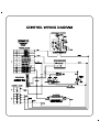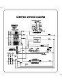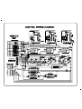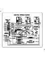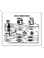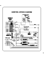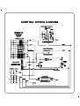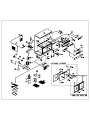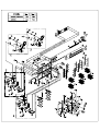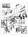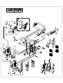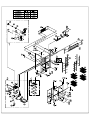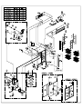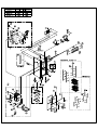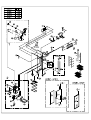
1
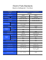
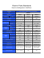
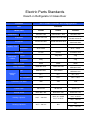
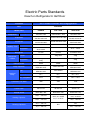
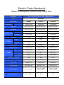
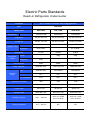
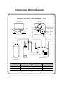
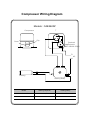
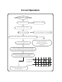
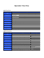
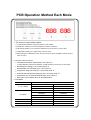
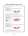
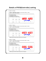
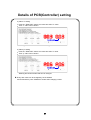
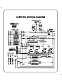
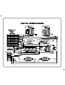
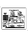
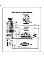
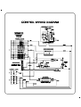
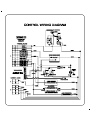
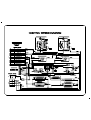
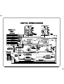
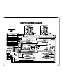
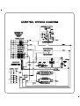
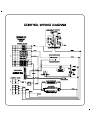
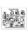
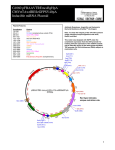
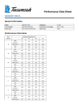
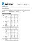
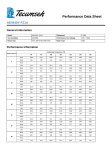
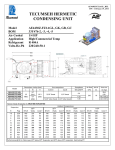
SERVICE MANUAL
COMMERCIAL REFRIGERATORS AND FREEZERS
Rev. APRIL 2008
KP
KP
KP
KP
KP
KP
KP
KP
KP
KP
KP
KP
KP
KP
KP
KP
KP
KP
KP
KP
KP
KP
KP
KP
KP
SR1
SR2
SR3
SR1H
SR2H
SR3H
GR1
GR2
GR3
SF1
SF2
SF3
SF1H
SF2H
SF3H
GF1
GF2
GF3
SRF2
SRF3
SRF1H
SRF2H
SRF3H
GRF2
GRF3
KP
KP
KP
KP
KP
KP
SUR2
GUR2
SUF2
GUF2
SURF2
GURF2
BLUE AIR Commercial Refrigeraton
TABLE OF CONTENS
▪ Safety Precautions for Customer Services
▪ Elextric parts Standards
▪ System Diagram of refigeration Cycle
▪ Functional Structure for Each Model
▪ Compressor Wiring Diagram
▪ Circuit Operation Method Each Mode
▪ PCB Operration Method Each Mode
▪ Refrigerator Troubl Shooting
▪ Solution for Troubl Shooting
▪ Control Wiring Diagram
▪ Exploded Diagram & Part List
3
4
15
17
19
21
23
26
28
30
61
Safety Precautions for Customer Services
Important!
Please Read Before Starting
This Reach-in refrigerator system meets strict safety and
operating standards.
As the installer or service person, it is an important part of
your job to install or service the system so it operates safely
and efficiently.
For safe installation and trouble-free operation,
you must:
● carefully read this instruction booklet before beginning.
● Follow each installation or repair step exactly as shown.
● Observe all local, state, and national electrical codes.
● Pay close attention to all warning and caution notices
given in this manual.
This symbol refers to a hazard or
unsafe practice which can result
in severe personal injury or death.
This symbol refers to a hazard or
unsafe practice which can result
in personal injury or property
damage.
If Necessary, Get Help
These instructions are all you need for most installstion
sites and maintenance conditions.
If you require help for a special problem, contact out
sales/service outlet or your certified dealer for additional
instructions.
In Case of Improper Installation
The manufacturer shall in no way be responsible for
improper installation or maintenance service, including
failure to follow the instructions in this document.
Special precautions
When wiring
ELECTRICAL SHOCK CAN CAUSE
SEVERE PERSONAL INJURY OR
DEATH. ONLY A QUALIFIED,
EXPERIENCED ELECTRICIAN
SHOULD ATTEMPT WIRE THIS
SYSTEM.
not supply power to the unit until all wiring and tubing
• Do
are completed or reconnected and checked.
Highly dangerous electeical voltages are used in this
• system.
Carefully refer to the wiringdiagram and these
•
•
instructions when wiring. Improper connections and
indequate grounding can cause accidental iniurv or death.
Ground unit follwing local electrical codes.
Connect all wiring tightly. Loose wiring may cause
ovetheating connection points and a possible fire hazaed.
When Installing...
The following conditions should be considered when
installing the refrigerator.
• Electric Supply
Supply voltage requirement is on the cabinet serial plate.
Low or high voltage can detrimentally affect the refrigeratio
unit and it is recommended to use the electric socket only
for the refrigerator.
• Grounding
To prevent shock and fire hazards, be suretherefrigerator
is properled.
• Clearance
Refrigerators require a minimum clearance of 7 inches
between the back of the cabinet and the wall
• Ventilation
Refrigerators demand a sufficient amount of cool clean air.
Keep the refrigerator away from sunlight and other hert and
moisture generating equipment such as stoves, oven,
dishwashers, etc.
• Floor
Be sure the floor where you intend to install the refrigerator
is strong enough to support the total weight of the
refrigreator and its contenes.
• Level
To provide adequate drainage and proper door operation,
is necessary that the refrigerator be level. this xhould be
done after the refrigerator is set in its final operation positio
When servicing
• Turn the power off at the main power box(mains) before
•
•
opening the unit to check or repair electrical parts and
wiring.
Keep your fingers and clothing away from any moving
parts.
Clean up the site sfter you finsh, remembering to check
that no metal scraps or bits of wiring have been left insid
the unit being serviced.
OTHERS
any enclosed areas when installing or testing
• Ventilate
the refrigeration system. Escaped refrigerant gas, on
contact with or heat, can produce dangerously toxic gas
upon completing installstion that no refrigerant
• Confirm
gas is leaking. If escaped gas comes in contact with a
stove, gas water heater, electric room hester or other
heat source, it can produce dangerously toxic gas.
When Transporting
Be careful when picking up and moving the units
Get a partner to help, and bend your knees When lifting to
reduce strain on your back.
Sharp edges or thin aluminum fins on the Reach-in refrigerato
can cut your fingers.
Wash hands after handing
Handling the cord on this product or cords associated with
aaccessories sold with this product, will expose you to lead
a chemical known to the State of Dalifornia to caner, and
birth defects or other repoductive harm.
Electric Parts Standards
Reach-in Refrigerator 1 Full Door
Division
Air-Cooled Freezer and Regrigerator
Item
Standards
Model name
KPSR1
KPSF1
AE4430Y-1SR
CAE2420Z
Evaporator
3/8" 3R × 10S × 310L
3/8" 3R × 12S × 310L
Condenser
3/8" 3R × 8S × 280L
3/8" 4R × 8S × 280L
-
Φ1.2 × 4600L
Φ1.2 × 1800L
-
R-134a
R-404a
-
320g
240g
-
Defrost Heater
280W
280W
Relay Operation
KEM 682
3ARR13KP*483
KEM 664-12C
MST16AHN
ON Temperature
61℃
69℃
OFF Temperature
105℃
120℃
Condenser Fan Moter
43W
43W
Evporator Fan Moter
9W
9W
Power Code
Φ1.2㎣ × 3C
Φ1.2㎣ × 3C
Ground Screw
Brass Bolt / Nut
Brass Bolt / Nut
Starting Capacitor
120㎌ ~ 250 Vac
160V~40 ÷ 60HZ
315㎌-0+20%e
Running Capacitor
30㎌ ~ 440 Vac
NONE
Type
Compressor
Freezer
Capillary Tube
Refrigerator
Refrigerant
Refrigerant
Volume
Freezer
Refrigerator
Type
Overlord
Relay
Electric Parts Standards
Reach-in Refrigerator 1 Full Door
Division
Air-Cooled Freezer and Regrigerator
Item
Standards
Model name
KPGR1
KPGF1
AE4430Y-1SR
CAE2424Z / CAE2420Z
Evaporator
3/8" 3R × 10S × 310L
3/8" 3R × 12S × 310L
Condenser
3/8" 3R × 8S × 280L
3/8" 4R × 8S × 280L
-
Φ1.2 × 4600L
Φ1.2 × 1800L
-
R-134a
R-404a
-
320g
240g
-
Defrost Heater
280W
280W
Relay Operation
KEM 682-13NT
3ARR13KP*483
KEM 664-12/C
MST16AHN
ON Temperature
61℃
69℃
OFF Temperature
105℃
120℃
Condenser Fan Moter
43W
43W
Evporator Fan Moter
9W
9W
Power Code
Φ2.0㎣ × 3C
Φ2.0㎣ × 3C
Ground Screw
Brass Bolt / Nut
Brass Bolt / Nut
Starting Capacitor
120㎌ ~ 250 Vac
160V~40 ÷ 60HZ
315㎌-0+20%e
Running Capacitor
30㎌ ~ 440 Vac
NO
Type
Compressor
Freezer
Capillary Tube
Refrigerator
Refrigerant
Refrigerant
Volume
Freezer
Refrigerator
Type
Overlord
Relay
Electric Parts Standards
Reach-in Refrigerator 2 Half Door
Division
Air-Cooled Freezer and Refrigerator
Item
Standards
Model name
KPSR1H
KPSF1H
KPSRF1H
AE4430Y-1SR
CAE2420Z
CAE2420Z
Evaporator
3/8" 3R × 10S × 310L
3/8" 3R × 12S × 310L
3/8" 3R × 10S × 310L
2EA
Condenser
3/8" 3R × 8S × 280L
3/8" 4R × 8S × 280L
3/8" 4R × 8S × 280L
Φ1.2 × 4600L
Φ1.2 × 4600L
Type
Compressor
Freezer
Capillary Tube
Refrigerator
Refrigerant
Φ1.2 × 1800L
Φ1.2 × 1800L
R-134a
R-404a
R-404a
-
320g
350g
240g
-
-
Defrost Heater
280W
280W
280W
Relay Operation
KEM 682-13NT
3ARR13KP*483
3ARR13KP*483
KEM 664-12/C
MST16AHN
MST16AHN
ON Temperature
61℃
69℃
69℃
OFF Temperature
105℃
120℃
120℃
Condenser Fan Moter
43W
43W
43W
Evporator Fan Moter
9W
9W
9W
Power Code
Φ2.0㎣ × 3C
Φ2.0㎣ × 3C
Φ2.0㎣ × 3C
Ground Screw
Brass Bolt / Nut
Brass Bolt / Nut
Brass Bolt / Nut
Starting Capacitor
120㎌ ~ 250 Vac
160V~40 ÷ 60HZ
315㎌-0+20%e
160V~40 ÷ 60HZ
315㎌-0+20%e
Running Capacitor
30㎌ ~ 440 Vac
NO
NO
Refrigerant
Volume
Freezer
Refrigerator
Type
Overlord
Relay
Electric Parts Standards
Reach-in Refrigerator 4 Half Door
Division
Air-Cooled Freezer and Regrigerator
Item
Standards
Model name
KPSR2H
KPSF2H
AE4440Y-1SR
CAE2420ZA × 2EA
Evaporator
3/8" 3R×12S×310L
3/8"3R×12S×310L×2EA
Condenser
3/8" 3R×8S×280L
3/8"4R×8S×280L×2EA
-
Φ1.2 × 4600L×2EA
Φ1.2 × 4600L
Φ1.2 × 1800L
-
Φ1.2 × 1800L
R-134a
R-404a
R-404a / R-134a
-
320g×2EA
320g
260g
-
240g
Defrost Heater
280W
280W×2EA
280W×2EA
Relay Operation
KEM 682-19NT
3ARR13KP*483
KEM 660-42/C
MST16AHN
ON Temperature
61℃
69℃
69℃
OFF Temperature
105℃
120℃
120℃
Condenser Fan Moter
43W
43W
43W
Evporator Fan Moter
9W
9W
9W
Power Code
Φ2.0㎣×3C
Φ2.0㎣×3C
Φ2.0㎣×3C
Ground Screw
Brass Bolt / Nut
Brass Bolt / Nut
Brass Bolt / Nut
120㎌ ~ 250 Vac
160V~40 ÷ 60HZ
315㎌-0+20%e
Type
Compressor
Freezer
KPSRF2H
CAE2420ZA
AE4430Y-1SR
3/8"3R×12S×310L
3/8"3R×10S×310L
3/8"4R×8S×280L
3/8"3R×8S×280L
Capillary Tube
Refrigerator
Refrigerant
Refrigerant
Volume
Freezer
Refrigerator
Type
Overlord
Relay
Starting Capacitor
3ARR13KP*483
KEM 682-19NT
MST16AHN
KEM 664-12/C
160V~40 ÷ 60HZ
315㎌-0+20%e
120㎌ ~250 Vac
30㎌ ~ 440 Vac
Running Capacitor
20㎌ ~ 440 Vac
NO
NO
Electric Parts Standards
Reach-in Refrigerator 2 Glass Door
Division
Air-Cooled Freezer and Regrigerator
Item
Standards
Model name
KPGR2
KPGF2
AE4440Y-1SR
CAE2420ZA × 2EA
Evaporator
3/8"3R×12S×310L
3/8"3R×12S×310L×2EA
Condenser
3/8"3R×8S×280L
3/8"4R×8S×280L×2EA
Type
Compressor
Freezer
Φ1.2 × 4600L×2EA
KPGRF2
CAE2420ZA
AE4430Y-1SR
3/8"3R×12S×310L
3/8"3R×10S×310L
3/8"4R×8S×280L
3/8"3R×8S×280L
Φ1.2 × 4600L
Capillary Tube
Refrigerator
Refrigerant
Refrigerant
Volume
Φ1.2×1800L
R-134a
Freezer
Refrigerator
Φ1.2 × 1800L
R-404A
R-404A/R-134a
320g×2EA
320g
260g
240g
Defrost Heater
280W
280W
Relay Operation
KEM 682-19NT
3ARR13KP*483
KEM 660-42/C
MST16AHN
ON Temperature
61℃
69℃
69℃ / 61℃
OFF Temperature
105℃
120℃
120℃ / 105℃
Condenser Fan Moter
43W
43W
43W
Evporator Fan Moter
9W
9W
9W
Power Code
Φ2.0㎣×3C
Φ2.0㎣×3C
Φ2.0㎣×3C
Ground Screw
Brass Bolt / Nut
Brass Bolt / Nut
Brass Bolt / Nut
120㎌ ~ 250 Vac
160V~40 ÷ 60HZ
315㎌-0+20%e
Type
Overlord
Relay
Starting Capacitor
280W
3ARR13KP*483
KEM 682-13NT
MST16AHN
KEM 664-12/C
160V~40 ÷ 60HZ
315㎌-0+20%e
120㎌ ~250 Vac
NO
Running Capacitor
20㎌ ~ 440 Vac
NO
30㎌ ~ 440 Vac
Electric Parts Standards
Reach-in Refrigerator 4 Half Door
Division
Air-Cooled Freezer and Regrigerator
Item
Standards
Model name
KPSR2H
KPSF2H
AE4440Y-1SR
CAE2420ZA × 2EA
Evaporator
3/8"3R×12S×310L
3/8"3R×12S×310L×2EA
Condenser
3/8"3R×8S×280L
3/8"4R×8S×280L×2EA
Type
Compressor
Freezer
Φ1.2 × 4600L×2EA
KPSRF2H
CAE2420ZA
AE4430Y-1SR
3/8"3R×12S×310L
3/8"3R×10S×310L
3/8"4R×8S×280L
3/8"3R×8S×280L
Φ1.2 × 4600L
Capillary Tube
Refrigerator
Refrigerant
Refrigerant
Volume
Φ1.2×1800L
R-134a
Freezer
Refrigerator
Φ1.2 × 1800L
R-404A
R-404A/R-134a
320g×2EA
320g
260g
240g
Defrost Heater
280W
280W
Relay Operation
KEM 682-19NT
3ARR13KP*483
KEM 660-42/C
MST16AHN
ON Temperature
61℃
69℃
69℃ / 61℃
OFF Temperature
105℃
120℃
120℃ / 105℃
Condenser Fan Moter
43W
43W
43W
Evporator Fan Moter
9W
9W
9W
Power Code
Φ2.0㎣×3C
Φ2.0㎣×3C
Φ2.0㎣×3C
Ground Screw
Brass Bolt / Nut
Brass Bolt / Nut
Brass Bolt / Nut
120㎌ ~ 250 Vac
160V~40 ÷ 60HZ
315㎌-0+20%e
Type
Overlord
Relay
Starting Capacitor
280W
3ARR13KP*483
KEM 682-13NT
MST16AHN
KEM 664-12/C
160V~40 ÷ 60HZ
315㎌-0+20%e
120㎌ ~250 Vac
NO
Running Capacitor
20㎌ ~ 440 Vac
NO
30㎌ ~ 440 Vac
Electric Parts Standards
Reach-in Refrigerator 3 Full Door
Division
Air-Cooled Freezer and Regrigerator
Item
Standards
Model name
KPSR3
Type
Compressor
Evaporator
Condenser
AE4440Y-1SR
AE4430Y-1SR
3/8"3R×12S×310L
3/8"3R×10S×310L
3/8"3R×8S×280L
3/8"3R×8S×280L
Freezer
Capillary Tube
Refrigerator
Refrigerant
Refrigerant
Volume
Defrost Heater
Relay Operation
Type
Overlord
Relay
CAE2420ZA × 3EA
3/8"4R×12S×310L×3EA
3/8"4R×8S×280L×3EA
Φ1.2 × 4600L×3EA
Φ1.2×1800L
Φ1.2×1800L
R-134a
Freezer
Refrigerator
KPSF3
KEM 682-19NT
KEM 682-13NT
KEM 660-42/C
KEM 664-12/C
CAE2420ZA
AE4440Y-1SR
3/8"3R×12S×310L
3/8"3R×12S×310L
3/8"4R×8S×280L
3/8"3R×8S×280L
Φ1.2 × 4600L
Φ1.2 × 1800L
R-404A
R-404A/R-134a
320g×3EA
320g
260g
240g
280W
KPSRF3
260g
280W
3ARR13KP*483
MST16AHN
280W
3ARR13KP*483
KEM 682-19NT
MST16AHN
KEM 664-42C
ON Temperature
61℃
69℃
69℃ / 61℃
OFF Temperature
105℃
120℃
120℃ / 105℃
Condenser Fan Moter
43W
43W
43W
Evporator Fan Moter
9W
9W
9W
Power Code
Φ2.0㎣×3C
Φ2.0㎣×3C
Φ2.0㎣×3C
Ground Screw
Brass Bolt / Nut
Brass Bolt / Nut
Brass Bolt / Nut
Starting Capacitor
120㎌ ~ 250 Vac
120㎌ ~ 250 Vac
160V~40 ÷ 60HZ
315㎌-0+20%e
20㎌ ~ 440 Vac
30㎌ ~ 440 Vac
NO
Running Capacitor
160V~40 ÷ 60HZ
315㎌-0+20%e
120㎌ ~250 Vac
NO
20㎌ ~ 440 Vac
Electric Parts Standards
Reach-in Refrigerator 3 Glass Door
Division
Air-Cooled Freezer and Regrigerator
Item
Standards
Model name
KPGR3
Type
Compressor
Evaporator
Condenser
AE4440Y-1SR
AE4430Y-1SR
3/8"3R×12S×310L
3/8"3R×10S×310L
3/8"3R×8S×280L
3/8"3R×8S×280L
Freezer
Capillary Tube
Refrigerator
Refrigerant
Refrigerant
Volume
Defrost Heater
Relay Operation
Type
Overlord
Relay
CAE2420ZA × 3EA
3/8"3R×12S×310L×3EA
3/8"4R×8S×280L×3EA
Φ1.2 × 4600L×3EA
Φ1.2×1800L
Φ1.2×1800L
R-134a
Freezer
Refrigerator
KPGF3
KEM 682-19NT
KEM 682-13NT
KEM 660-42/C
KEM 664-12C
CAE2420ZA
AE4440Y-1SR
3/8"3R×12S×310L
3/8"3R×12S×310L
3/8"4R×8S×280L
3/8"3R×8S×280L
Φ1.2 × 4600L
Φ1.2 × 1800L
R-404A
R-404A/R-134a
320g×3EA
320g
260g
240g
280W
KPGRF3
260g
280W
3ARR13KP*483
MST16AHN
280W
3ARR13KP*483
KEM 682-19NT
MST16AHN
KEM 664-42C
ON Temperature
61℃
69℃
69℃ / 61℃
OFF Temperature
105℃
120℃
120℃ / 105℃
Condenser Fan Moter
43W
43W
43W
Evporator Fan Moter
9W
9W
9W
Power Code
Φ2.0㎣×3C
Φ2.0㎣×3C
Φ2.0㎣×3C
Ground Screw
Brass Bolt / Nut
Brass Bolt / Nut
Brass Bolt / Nut
Starting Capacitor
120㎌ ~ 250 Vac
120㎌ ~ 250 Vac
160V~40 ÷ 60HZ
315㎌-0+20%e
20㎌ ~ 440 Vac
30㎌ ~ 440 Vac
NO
Running Capacitor
160V~40 ÷ 60HZ
315㎌-0+20%e
120㎌ ~250 Vac
NO
20㎌ ~ 440 Vac
Electric Parts Standards
Reach-in Refrigerator 6 Half Door
Division
Air-Cooled Freezer and Regrigerator
Item
Standards
Model name
KPSR3H
Type
Compressor
Evaporator
Condenser
AE4440Y-1SR
AE4430Y-1SR
3/8"3R×12S×310L
3/8"3R×10S×310L
3/8"3R×8S×280L
3/8"3R×8S×280L
Freezer
Capillary Tube
Refrigerator
Refrigerant
Refrigerant
Volume
Defrost Heater
Relay Operation
Type
Overlord
Relay
CAE2420ZA × 3EA
3/8"3R×12S×310L×3EA
3/8"4R×8S×280L×3EA
Φ1.2 × 4600L×3EA
Φ1.2×1800L
Φ1.2×1800L
R-134a
Freezer
Refrigerator
SRF-72HD
KEM 682-19NT
KEM 682-13NT
KEM 660-42/C
KEM 664-12/C
CAE2420ZA
AE4440Y-1SR
3/8"3R×12S×310L
3/8"3R×12S×310L
3/8"4R×8S×280L
3/8"3R×8S×280L
Φ1.2 × 4600L
Φ1.2 × 1800L
R-404A
R-404A/R-134a
320g×3EA
320g
260g
240g
280W
SRD-72HD
260g
280W
3ARR13KP*483
MST16AHN
280W
3ARR13KP*483
KEM 682-19NT
MST16AHN
KEM 664-12/C
ON Temperature
61℃
69℃
69℃ / 61℃
OFF Temperature
105℃
120℃
120℃ / 105℃
Condenser Fan Moter
43W
43W
43W
Evporator Fan Moter
9W
9W
9W
Power Code
Φ2.0㎣×3C
Φ2.0㎣×3C
Φ2.0㎣×3C
Ground Screw
Brass Bolt / Nut
Brass Bolt / Nut
Brass Bolt / Nut
120㎌ ~ 250 Vac
Starting Capacitor
120㎌ ~ 250 Vac
160V~40 ÷ 60HZ
315㎌-0+20%e
120㎌ ~250 Vac
NO
20㎌ ~ 440 Vac
Running Capacitor
160V~40 ÷ 60HZ
315㎌-0+20%e
NO
30㎌ ~ 440 Vac
20㎌ ~ 440 Vac
Electric Parts Standards
Reach-in Refrigerator Undercounter Glass Door
Division
Air-Cooled Freezer and Regrigerator
Item
Standards
Model name
KPSUR2
KPSUF2
KPSURF2
AE4430Y-1SR
CAE2420ZA
CAE2420ZA
Evaporator
3/8"3R×10S×310L
3/8"3R×12S×310L
3/8"3R×10S×310L
Condenser
3/8"2R×11S×180L
3/8"3R×11S×180L
3/8"3R×11S×180L
-
Φ1.2 × 4600L
Φ1.2 × 4600L
Φ1.2×1800L
-
Φ1.2×1800L
R-134a
R-404a
R-404a
-
320g
350g
240g
-
-
Defrost Heater
280W
280W
280W
Relay Operation
KEM 682-13NT
3ARR13KP*483
3ARR13KP*483
KEM 664-12/C
MST16AHN
MST16AHN
ON Temperature
61℃
69℃
69℃ / 61℃
OFF Temperature
105℃
120℃
120℃ / 105℃
Condenser Fan Moter
43W
43W
43W
Evporator Fan Moter
9W
9W
9W
Power Code
Φ2.0㎣×3C
Φ2.0㎣×3C
Φ2.0㎣×3C
Ground Screw
Brass Bolt / Nut
Brass Bolt / Nut
Brass Bolt / Nut
Starting Capacitor
120㎌ ~ 250 Vac
160V~40 ÷ 60HZ
315㎌-0+20%e
160V~40 ÷ 60HZ
315㎌-0+20%e
Running Capacitor
20㎌ ~ 440 Vac
NO
NO
Type
Compressor
Freezer
Capillary Tube
Refrigerator
Refrigerant
Refrigerant
Volume
Freezer
Refrigerator
Type
Overlord
Relay
Electric Parts Standards
Reach-in Refrigerator Undercounter
Division
Air-Cooled Freezer and Regrigerator
Item
Standards
Model name
SRR-16GD
SRF-16GD
SRD-16GD
AE4430Y-1SR
CAE2420ZA
CAE2420ZA
Evaporator
3/8"3R×10S×310L
3/8"3R×12S×310L
3/8"3R×10S×310L
Condenser
3/8"2R×11S×180L
3/8"3R×11S×180L
3/8"3R×11S×180L
-
Φ1.2 × 4600L
Φ1.2 × 4600L
Φ1.2×1800L
-
Φ1.2×1800L
R-134a
R-404A
R-404A
-
320g
350g
240g
-
-
Defrost Heater
280W
280W
280W
Relay Operation
KEM 682-13NT
3ARR13KP*483
3ARR13KP*483
KEM 664-12/C
MST16AHN
MST16AHN
ON Temperature
61℃
69℃
69℃
OFF Temperature
105℃
120℃
120℃
Condenser Fan Moter
43W
43W
43W
Evporator Fan Moter
9W
9W
9W
Power Code
Φ2.0㎣×3C
Φ2.0㎣×3C
Φ2.0㎣×3C
Ground Screw
Brass Bolt / Nut
Brass Bolt / Nut
Brass Bolt / Nut
Starting Capacitor
120㎌ ~ 250 Vac
160V~40 ÷ 60HZ
315㎌-0+20%e
160V~40 ÷ 60HZ
315㎌-0+20%e
Running Capacitor
30㎌ ~ 440 Vac
NO
NO
Type
Compressor
Freezer
Capillary Tube
Refrigerator
Refrigerant
Refrigerant
Volume
Freezer
Refrigerator
Type
Overlord
Relay
System Diagram pf Refigeration Cycle
Refregeration
Freezer
MODELS: KPSR1H
KPSR1
KPGR1
KPSUR2
KPGUR2
EVAPORATOR
● WELDING POINT
MODELS: KPSF1H
KPSF1
KPGF1
KPSUF2
KPGUF2
EVAPORATOR
● WELDING POINT
ACCUNULAT
ACCUNULAT
CAPPILARY
CAPPILARY
DRYE
DRYE
CHARGE
CHARGE
CHARGE
CHARGE
1/2 H.P
1/4 H.P
COMPRESS
COMPRESS
CONDENSER
Refregeration
CONDENSER
Refregeration/Fre
MODELS: KPSR2H
KPSR2
KPGR2
EVAPORATOR
EVAPORATOR
MODELS: KPSRF1H
KPSURF2
● WELDING POINT
● WELDING POINT
ACCUNULAT
S/VALVE
CAPPILARY
DRYE
DRYE
CHARGE
CHARGE
CHARGE
CHARGE
CAPPILARY
ACCUNULAT
1/2 H.P
1/3 H.P
COMPRESS
COMPRESS
CONDENSER
CONDENSER
RefregerationMODESL: KPSRF2H
KPSRF2
KPGRF2
KPSRF3H
KPSRF3
KPGRF3
EVAPORATOR
● WELDING POINT
Freezer
EVAPORATOR
● WELDING POINT
ACCUNULAT
ACCUNULAT
CAPPILARY
CAPPILARY
DRYE
DRY
CHARGE
CHARGE
1/3 H.P or 1/4 H.P
COMPRESS
CHARGE
CHARGE
1/2 H.P
CONDENSER
COMPRESS
CONDENSER
System Diagram pf Refigeration Cycle
Refregeration
EVAPORATOR
MODEL: KPSR3H
KPSR3
KPGR3
EVAPORATOR
● WELDING POINT
● WELDING POINT
ACCUNULAT
ACCUNULAT
CAPPILARY
CAPPILARY
DRYE
DRYE
CHARGE
CHARGE
CHARGE
CHARGE
1/4 H.P
1/3 H.P
COMPRESS
COMPRESS
CONDENSER
Freezer
EVAPORATOR
MODEL: KPSF2H
KPSF2
KPGF2
CONDENSER
EVAPORATOR
● WELDING POINT
● WELDING POINT
ACCUNULAT
ACCUNULAT
CAPPILARY
CAPPILARY
DRYE
DRYE
CHARGE
CHARGE
CHARGE
1/2 H.P
1/2 H.P
COMPRESS
COMPRESS
CONDENSER
Freezer
CONDENSER
MODEL: KPSF3H
KPSF3
KPGF3
EVAPORATOR ASSEMBLY
EVAPORATOR
EVAPORATOR
● WELDING POINT
● WELDING
● WELDING
ACCUNULAT
ACCUNULAT
ACCUNULATO
CAPPILARY
CAPPILARY
CAPPILARY
DRYE
CHARGE PORT
DRYER
DRYER
CHARGE
CHARGE PORT
CHARGE PORT
CONDENSER
COMPRESSOR
CHARGE PORT
CHARGE
1/2 H.P
1/2 H.P
1/2 H.P
COMPRESSOR
CHARGE
CONDENSER ASSEMBLY
COMPRESSOR
CONDENSER ASSEMBLY
Functional Structure for Each Model
KPSRF1H
KPSRF2H
REFRIGERATIO
FREEZER
KPSF2H
FREEZER
FREEZER
FREEZER
KPSR2H
REFRIGERATION
REFRIGERATION
REFRIGERATION
KPSF1H
FREEZER
KPSRF2
KPSRF2
KPSR1H
REFRIGERATION
KPSF2
KPGF2
Half Door
FREEZER
FREEZER
KPSR2
KPGR2
REFRIGERATION
KPSF1
KPGF1
FREEZER
KPSR1
KPGR1
REFRIGERATION
REFRIGERATION
Full & Glass Door
KPSRF2HQ
Functional Structure for Each Model
Full & Glass Door
Half Door
KPSR3
KPGR3
KPSRF3
KPGRF3
KPSF3
KPGF3
KPSR3H
KPSRF3H
Under Counter Half Door
KPSUR2
KPSURF2
KPSUF2
Under Counter Glass Door
KPGUR2
KPGURF2
KPGUF2
FREEZER
FREEZER
FREEZER
REFRIGERATION
REFRIGERATION
REFRIGERATION
FREEZER
FREEZER
FREEZER
1
REFRIGERATION
REFRIGERATION
REFRIGERATION
1
KPSF3H
Compressor Wiring Diagram
Models : AE4430-1SR, AE4440Y-1SR
Compress
Terminal
(MKE 660-42C)
(AE4440Y)
Overload
Protector
(MKE 66412/C)
Cilp
Cover
R
AC
N
Runing
Capacito
Starting
Capacito
Starting Relay
Model
Starting Capacitor
Running Capacitor
Starting Relay
AE4430Y-1SY
120㎌ 250Vac
30㎌ 440Vac
KME 682-13NT
AE4440Y-1SY
120㎌ 250Vac
20㎌ 440Vac
KME 682-19NT
Compressor Wiring Diagram
Models : CAE2420Z
Compressor
T
Cilp
Cover
Overload
Protector
(MKE 16AHN-3240)
R
AC
N
Starting
Starting Relay
Model
Starting Capacitor
Starting Relay
CAE2420Z
315㎌
3ARR13KP * 483
Circuit Operation
Product installation Copletion
Plug the power cord.
Power is 115V × 60Hz.
Tun on the power switch.
Check the Display.
The current temperature is displayed.
Press the "SET.TEMP" button an then the set temperture.
Check the Compressor
ti
Set the desird temperature for
storage/preservation.
A range of temperature
sdjustment
All the compressors have five minute delay
prior to their operationd sach time they ard turned
When the Temperature set is same as the
current temperature, the COMP is
Set temperature +2℃
Set temperature
Set temperature -1℃
Start/end operation by using
the power button.
<Comp ON/OFF dispayed of grape>
Operation Time Flow
※ Cooling Cycle
Cooling
LAMP
COMPRESSOR
COND FAN MOTOR
DOOR HEATER
EVAPORATOR HEATER
(Drain box heater)
DEFROST HEATER
DRAIN HEATER
EVAP. FAN MOTOR
Lighted on when the door is opened by the door switch. (Lighted on by switch in glass door unit.)
Set value "o".
Running off at set temperature value.running on at set value "o".
Run with compressor.
Running off at set temperature value. Runing on at set value "o".
Keep running
Keep running. It's controled by thermal protector.
Running off
Running off
Keep running, Running off when the door is opened.
※ Defrosting Cycle
Defrosting
LAMP
COMPRESSOR
COND FAN MOTOR
DOOR HEATER
EVAPORATOR HEATER
(Drain box heater)
DEFROST HEATER
DRAIN HEATER
EVAP FAN MOTOR
Cooling
Lighted on when the door is opened by the door switch. (Lighted on by switch in glass door unit.)
Running off during defrosting time, Running 3 min. later again after defrosting.
Running off during defrosting time, Running 3 min. later again after defrosting.
Keep running
Keep running. It's controled by thermal protector.
Running off when EVAP. coil temperature goes up being set value "t"
Running with defrosting, 3 min. more after defrosting.
Running off during defrosting time, Running 1 min. later again after compressor runing.
※ Initiall set value : FFF, H04, t56, C03, O6, D30, P06
PCB Operation Method Each Mode
1. The common value setting method
1) "A ON/OFF & B ON/OFF" are power switch for each cabinet.
2) "TEMP.SET" makes you to set the temperature value in all cabinet.
3) "SELETION" makes you to choose the cabinet that you want when you set a value.
4) "UP&DOWN" makes you to adjust every commom value.
5) Hold pushing the "TEMP.SET" button for five seconds, it can be available to set the common
value of control.
2. Common value of Control
• Temperature deviation adjustment(0°~9°F) value "H".
─
To adjust different measurement between on PCB and thermo sensor due to wire length.
•
•
•
•
•
•
Defrosting time setting (1~60 minutes) value "d".
Defrost heater turn off setting (37°F~90°F) value "t".
Compressor delay time setting (1~15 minutes) value "C".
Automatic defrosting period setting (every1~24 hours) value "P".
Compressor turn on deviation adjustment(1~20°F) value "o".
Each value can be adjust ed by UP & DOWN button.
3. PCB Mode
PCB Mode
A-1, A-1 Mode
A-1 Mode
A-2 Mode
b-1, b-1 Mode
C-1 & C-1 Mode
Appliation For Model
KPSRF2H
KPSRF3H
KPSR3H
KPSUF2
KPSUR2
KPSR1H
KPSF1H
KPSF2H
KPSRF1H
KPSF3H
KPSRF2, KPGRF2
KPSRF3, KPGRF3
KPSR3, KPGR3
KPGUF2
KPGUR2
KPSR1, KPGR1
KPSR2, KPGR2
KPSF2, KPGF2
KPSURF2, KPGURF2
KPSF3, KPGF3
Details of PCB(Controller) setting
1. Common value of control select
1) Temperature setting
• Push the "TEMP.SET" button and you can see the current set value with blinking red dot .
blinking dot
• You can set the temperature value by "UP & DOWN" button.
• Finally you must to push "TEMP.SET" button one more time and the inside cabinet
temperature is set.
• When the cabinet are two, you can select the cabinet by "SELECTION" button below picture.
move blinking
push
2. Common value of Control setting
1) Value "H" setting
Hold pushing the "TEMP.SET" button for five seconds and the windows will be changed.
•
blinking dot
•
*Blinking dot shows window that can be changed.
The "H" value is not necessary to change. Because "H" is fixed value at the factory.
25
Details of PCB(Controller) setting
2) Value "d" setting
Push the "TEMP.SET" button one more time after "H" value.
Then "d" value can be shown.
•
•
blinking dot
*Blinking dot shows window that can be changed.
2) Value "t" setting
Push the "TEMP.SET" button one more time after "d" value.
Then "t" value can be shown.
•
•
blinking dot
*Blinking dot shows window that can be changed.
2) Value "C" setting
Push the "TEMP.SET" button one more time after "t" value.
Then "C" value can be shown.
•
•
blinking dot
*Blinking dot shows window that can be changed.
26
Details of PCB(Controller) setting
2) Value "o" setting
Push the "TEMP.SET" button one more time after "C" value.
Then "o" value can be shown.
•
•
blinking dot
*Blinking dot shows window that can be changed.
2) Value "p" setting
Push the "TEMP.SET" button one more time after "o" value.
Then "p" value can be shown.
•
•
blinking dot
*Blinking dot shows window that can be changed.
♠ Every each value can be changed by "UP & DOWN"
and it's finished to push "TEMP.SET" button after changing a value.
27
Details of PCB(Controller) setting
3. Temperature "Mode" select
• Hold pushing the "TEMP.SET" button for five seconds and the windows will be changed.
blinking dot
• Hold pushing the "TEMP.SET" button more five seconds and the windows will be changed.
• "FFF"or"CCC" can be shown and you can change that by "UP & DOWN"button.
• Finally you must to push "TEMP.SET" button one more time and the temperature mode
is set with rebooting controller(It wouldn't be rebooted when the"Mode" isn't changed.).
28
Details of PCB(Controller) setting
3. Controller "Mode" select
• Hold pushing the "TEMP.SET" button for five seconds and the windows will be changed.
blinking dot
• Hold pushing the "TEMP.SET" button more five seconds and the windows will be changed.
• After "FFF"or"CCC" being shown, Push the "TEMP.SET" button one more.
• One of the "Mode" can be shown.
• You can change the "Mode" by "UP & DOWN" button
• Finally you must to push "TEMP.SET" button one more time and the mode is set
with rebooting controller(It wouldn't be rebooted when the"Mode" isn't changed.).
♠ Every type of the "Mode" is shown below.
<C-1,C-1>
29
Details of PCB(Controller) setting
<b-1,b-1>
<A-2>
<A-1,A-1>
<A-1>
30
Standard PCB(Controller) Setting
Reach-in Product
Direction
Range
Refrigerator
Freezer
H
00 degree ~ 09 degrees
4
4
● Temperature Deviation Adjustment(0°~9°F)
-To adjust different measurement between on PCB and thermo sensor due
to
wire length.
d
1min ~ 60min
30
20
37℉ ~ 90℉
50
57
3℃ ~ 32℃
13
14
● Defrosting Time setting
t
● Maximum EVAP. Coil temperature setting for defrosting.
C
01min ~ 15min
5
5
3
3
● Force the compressor delay time setting
o
1 degree ~ 20 degrees
● Compressor Turn ON Deviation Adjustmen
-The Cooling system will be operated when the inside cabinet temperature
goes
up set temperature to "o" value.
p
01hour ~ 24hours
● Automatic Defrosting Period Setting
31
12
3
PCB Operation Method Each Mode
Turn on the power switch
Press adjustment switch(Temp.set) for five
seconds.
Will be displayed "FFF" on PCB controller.
Press adjustment switch(Temo.set) for one time.
Will be displayed "CCC" on PCB controller.
Press "UP" or "DOWN" button decrease
time or increase time.
Press adjustment switch(Temo.set) for one time.
Will be displayed "H00" on PCB controller.
Press "UP" or "DOWN" button decrease
temperature or increase temperature.
Press adjustment switch(Temp.set) for one time.
Will be displayed "d00" on PCB controller.
Press "UP" or "DOWN" button decrease
time or increase time.
Press adjustment switch(Temp.set) for one time.
Press "UP" or "DOWN" button decrease
temperature or increase temperature.
Will be displayed "t00" on PCB controller.
To be continued
32
PCB Operation Method Each Mode
To be continued
Press adjustment switch(Temo.set) for one time.
Will be displayed "FFF" on PCB controller.
Will be displayed "CCC" on PCB controller.
It will be changed for current temperature.
33
Press "UP" or "DOWN" button decrease
time or increase time.
PCB Operation Method Each Mode
Pless adjustment switch(Temp.set) for five seconds
Will be displayed "H00" on PCB controller.
Hold on pressing adjustment
switch(Temp.set) for one more five seconds.
Will be displayed "A-1" on PCB controller.
Press "UP" or "DOWN" button change mode.
Will be displayed "A-2" on PCB controller.
Press "UP" or "DOWN" button change mode.
Will be displayed "b-1 & b-2" on PCB controller.
Press "UP" or "DOWN" button change mode.
Will be displayed "C-1 & C-1" on PCB controller.
Press "UP" or "DOWN" button change mode.
Will be displayed "C-1 & C-1" on PCB controller.
Press "UP" or "DOWN" button change mode.
Pless adjustment switch(temp.set)
It will be changed for current mode.
34
Trouble shooting
No cooling
Any message on the
controller(OP,SH)
Yes
OP : Sensor connection opened.
SH : Sensor connection shorted.
No
1. Gas leak : Evap. Coil are not cooled.
2. Poor compression of compressor.
3. The capillary tube Clogged.
Yes
Compressor is
working.
Yes
Condenser fan motor
is working.
No
Any failure on the
condenser fan motor.
Any failure on the
Evap. Fan motor
Yes
Yes
Evap. Fan motor
is working in the
cabinet.
No
No
Any failure on
the compressor
or running capacitor
or starting capacitor
Yes
No
Yes
No
The controller has to be checked
on the electric power source out
on the terminal block.
No power
35
Replace one
No
Trouble shooting
Poor cooling
Contents in cabinet
blocked air flow.
Condenser coil & air
filter are clogged.
Yes
No
The door was
opened repeatedly
No
Yes
Prevent this
condition
Yes
Ambient temperature
is too high(over 35℃).
NO
No
Yes
Any leakage around
the door gasket.
Yes
Repair or
replace one
NO
Too much frost
on the Evap. Coil.
NO
Any problem to
ventilate the
condensing unit.
No
Yes
Any failure on the
defrost heater.
No
Yes
Any failure on the
condenser fan motor
No
Yes
Any failure on
the controller.
Repair or
replace one
NO
Remove the frost on the Evap. Coil by manual
defrosting & adjust automatic defrosting period
36
Trouble shooting
There is any frost remaining on the evaporator coil.
● The defrost function is maintained by the common value "t", "d" & "p" on PCB.
Frost on
Evap. Coil
Manual defrost operation.
(Push the "SELECTION"
button for 10 sec.)
Manual defrost operation
displayed. (flashing "d00")
Replace the controller
No
Yes
Defrosting activated.
No
Any failure on
Evap. Coil sensor
No
Any failure on
defrost heater.
No
The controller has to be checked
on the electric power source out
on the dfrost heater terminal block.
No power
37
Replace the one