1
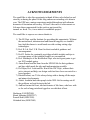
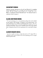
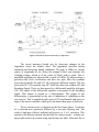
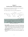
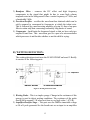
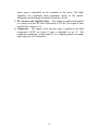
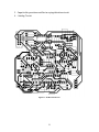
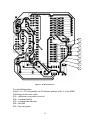
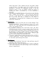
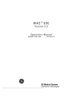
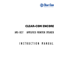
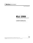
Hariharan Narayanan(98D07009) Shruti Mahajan(98D07017) Premal Shah(98D07020) Abhishek Jain(98D07040) Service Manual Neo-natal Monitor 1 Table of Contents Acknowledgements 2 Chapter 1 Introduction 3 Chapter 2 Breath rate measurement module 7 Chapter 3 Heartbeat rate measurement module 10 Chapter 4 Crying and wetting detection modules 12 Chapter 5 Temperature module 15 Chapter 6 System Specifications 17 Appendix 1 PCB Layouts 18 Appendix 2 Interfacing microcontroller with Bluetooth module 25 Appendix 3 Flow of control in C-code 28 Appendix 4 Overview of C-code and Perl Script 30 2 ACKNOWLEDGEMENTS We would like to take this opportunity to thank all those who helped us and stood by us during the phase of this long endeavour extending over about a year. The EDP was a unique experience marked throughout with alternate moments of frustration and ecstasy. All in all the sense of achievement we felt more than compensated for the work we put in and the turmoil we faced. Yes, it was indeed a worthwhile project! We would like to express our sincere thanks to 1) The EE Dept. and the Institute for providing this opportunity. Without the motivational, infrastructural and financial support, we wouldn’t have had the chance to work hands on with exciting cutting edge technologies. 2) Prof. R. Lal, Prof. U.B. Desai for their invaluable guidance and encouragement. 3) Prof D. Sarkar for constantly providing valuable insights and tips to overcome many of the technical hurdles we encountered. 4) Prof. Mukherjee of the BioMedical Dept. who took great pains to get our ECG module going. 5) Aman Kansal and the team from the SPANN lab for their guidance and tips which made the idea and implementation possible. 6) Dr. Rajan, Prof. Joshi and Mr. Kini of the IDC Dept.; without their active interest and help, our design could not have been converted to a boxed product. 7) Hitesh Kothari, our TA for always being with us during all the major and minor developments. 8) Ashok Ambalan and other people in the WEL lab for sorting out all the problems we kept facing in the lab. 9) And last but not the least, our batch mates of 8de fame, who bore with us for such a long period and egged us on with their efforts. Hariharan N (98D07009) Shruti Mahajan (98D07017) Premal Shah (98D07020) Abhishek Jain (98D07040) 3 Chapter 1 Introduction MobiCare Neonatal Monitor provides a convenient monitoring system that allows you to be informed about your child’s status whether you are at your home or at work. It is especially designed to be useful in both hospital and home environments with its compact portable design and better operability. We expect MobiCare Neonatal Monitor to provide reliable convenient monitoring with little problems. However in case of any difficulties please contact qualified personnel, preferably from the company. This manual gives the complete description of the system. A brief description of each component follows. A) ANALOG PROCESSING UNIT: MobiCare Neonatal Unit continuously monitors the breathing rate heartbeat-rate and temperature of the infant. In addition it checks for wetting and crying conditions. The analog measurement unit consists of modules to extract and process signals corresponding to the breathing rate, heartbeat rate, wetting and crying. 1) Breathing Rate Measurement Module: MobiCare Neonatal Monitor detects breathing efforts using the highly reliable transthorasic impedance method. A 100 A Ac current at 50 KHz that is considered safe is injected into the patients body through the two electrodes that are worn at the infants chest. The small deviations caused in the chest impedance during inhalation and exhalation efforts modulate this signal and the resulting voltages are accurately measured to detect breathing efforts. The complete description of the breath rate measuring module is given in chapter 2. 4 2) Heartbeat Rate Measurement Module : To make the system less intrusive and more comfortable to the baby MobiCare Neonatal Monitor uses the same electrodes for obtaining the ECG signal required for beat-rate estimation as those used for the breathing part. Beat rate measurements provide an additional degree of reliability especially in case of apnea conditions where there is no breathing inspite of efforts to breathe. The module filters out the high frequency signal generated by the breath rate circuit and then applies frequency selective filters to extract beat rates. The circuit has provision for filtering 50 Hz power line interference and is adaptable to varying signal strengths of the ECG signal. The module is explained in detail in Chapter 3. 3) Crying And Wetting Detection Modules: MobiCare Neonatal Monitor includes detection of crying and wetting by the infant for additional comfort. Crying is detected by applying filtering to an audio signal acquired from the baby. Change in impedance of a sensor provided with the module is used to detect wetting. For impedance measurement again low amplitude and high frequency signals are used to ensure maximum safety to the subject. More information about the same is provided in chapter 4. B) DIGITAL PROCESSING UNIT MobiCare Neonatal Monitor uses an 89C52 microcontroller based digital master to collect the data obtained by the analog modules. It also provides for the Digital to Analog Conversion of the temperature. The microcontroller also provides the driver for the bluetooth module. The microcontroller is capable of automatically discovering a local monitoring server in its vicinity. It also detects emergency causing situations and raises alarms locally as well at the monitoring server. The microcontroller functionality is explained in chapter 5. 5 C) BLUETOOTH MODULE: MobiCare Neonatal Monitor can work with any Bluetooth 1.1 compliant module implementing the HCI. It currently uses the Ericsson ROK 101 007 module. The host controller (microcontroller uses) a UART link at 57.6 KBps to communicate with the bluetooth card. The bluetooth model is explained in detail in chapter 6. D) LOCAL MONITORING SERVER: The local monitoring server is an application package that can be installed on any Windows 2000 machine. It includes its own bluetooth driver. The local monitoring server is capable of maintaining status of up to 7 kits for a hospital environment. It has a convenient graphical user interface for ease of operation and includes a http server to entertain queries from a http enabled client. Information about the local monitoring server is provided in chapter 6. E) REMOTE ENQUIRY DEVICE: Any device capable of acting as a http client such as a PC, laptop, PDA or cell-phone can be used to connect to the local monitoring server to enquire about the patient status. 6 Chapter 2 Breath Rate Measurement Module Figure 1: Breath rate detector circuit until body 7 Figure 2: Breath rate detector from body to comparators The circuit measures breath rate by observing changes in the impedance across the infant’s chest. The impedance increases during inhalation and decreases during exhalation. We apply a 50Khz ac current source of magnitude 40 A across the neonate's chest, and measure the resulting voltage, which is of the order of 50mV peak to peak. This is amplified and high pass filtered with a cutoff of 16Khz. We then perform a precision half wave rectification and then low pass filter the resultant waveform at cutoffs 3hz and 0.33 Hz, giving two different outputs. The one with cutoff 0.33 Hz contains only DC, while the other one contains DC and Breathing Signal. These are then passed to a differential amplifier with gain 100. The output of the differential amplifier corresponds to the breathing signal. This output is passed to a differentiator. The output of the differentiator is proportional to the rate of inhalation or exhalation as the case may be. This is amplified with a gain of 80, hard-limited, and given as input to the micro-controller, which gives an alarm when apnea is detected. The ac current source is depicted in the first figure above. It consists of a sawtooth wave generator followed by a low-pass filtering unit. The result is high-pass filtered, buffered and given to a V to I converter. This current is not directly injected into the baby for safety reasons – a faulty opamp could result in dc current being injected into the baby. Therefore the ac 8 current goes into the infant’s body via an RC high pass. The high pass components are chosen so that at 25hz, the impedance due to them is greater or equal to 2.5M. This is necessary because the heart rate is being measured too (which has a bandwidth of roughly 25 hz) and an external impedance across the body disturbs ecg readings. 9 Chapter 3 Heartbeat Rate Measurement Module This circuit measures the heartbeat-rate of the infant, which is displayed as the number of beats per minute on the web-page. The modules in this part of the circuit, with their peculiarities, are: Figure 3 Heartbeat rate detection circuit 1) Input amplifier – provides a gain of 22 to the input. ECG signal values from the body will range between 2 mV and 5 mV, so that the output typically lies between 40 mV and 110 mV. This signal comes mixed with a 50 kHz – 100 mV response of the body to the 100 A of AC current injected into the body to detect breathing. This high frequency signal is hence amplified to about 2.5 V. 2) Band-pass filter – has a passband of 8 Hz around 17 Hz; hence is a rather selective filter to pass only the peaks corresponding to the heartbeats. 10 It has a Q of 2.2. It also has a peak gain of 53. It is a second-order active filter. This removes the whole of high frequency component and attenuates the DC. 3) Low-pass filter – is added to refine the signal by weeding out unwanted higher frequencies in the ECG signal. It has a cut-off of 27 Hz and a gain of about 2 in the passband. After this, our required signal is of reasonable amplitude in the desired range of frequencies, even though 50 Hz might still be going strong. 4) Notch filter – drastically attenuates the interference around 50 Hz; which is present in the environment due to the operation of common electric devices at this frequency. The output of this stage is a “clean” sequence of peaks corresponding to the heartbeats, of amplitude of about 1 V. It has a Q factor of 1. The ECG signal is hence reduced to a frequency range of a few Hz around 17 Hz. This signal can be tested for at point A in figure 1. 5) Peak Detector – gives transitions corresponding to the peaks obtained above. These when passed through a high-pass filter of cut-off frequency 7 Hz give small short pulses. They are then amplified by a factor of 10 and compared against a threshold of about 1 V to obtain a sequence of 5 V pulses fed into the microcontroller as input. This output of the PCB can be seen at point ? in figure1. 11 Chapter 4 Crying and Wetting Detection Modules A) CRYING DETECTION: This part of the circuit takes the input from a microphone that is placed close to the infant’s mouth; the output is processed by the microcontroller to decide whether the baby is crying or not. Figure 4: Crying Detection Circuit The modules are as follows : 1) Microphone – a capacitative microphone that gives current proportional to the input signal. For zero input, we get an output of about 200 A when the mike can be assumed to provide a typical resistance of about 20K. Typical AC currents due to sound are of amplitude 50 A. 2) Current-to-Voltage Converter – is a simple opamp with a resistor in negative feedback that converts our input current to a corresponding voltage signal. The input signal of amplitude around 0.5 V comes added to a DC offset of 2 V for a 10 K resistor used here. 12 3) Bandpass Filter – removes the DC offset and high frequency components in the signal that might be due to some high volume temporal noise in the background. It has a center frequency of 1 kHz, and a bandwidth 2 kHz. 4) Precision Rectifier – rectifies the waveform thus obtained which can be safely assumed to correspond to frequencies at which the infant cries. This is followed by a non-inverting amplifier of gain 10, then a low-pass filter to retain only data concerning reasonably long bursts of sound. 5) Comparator – hard limits the lowpassed signal so that we have only two outputs Hi and Low. This waveform goes to a port of a microcontroller which processes it and decides whether or not the child is crying. B) WETTING DETECTION: The wetting detection circuit uses the LF442 OPAMP on board 2. Briefly it consists of the following parts. Figure 5: Wetting Detection Circuit 1) Wetting Probe - This is a simple sponge. Change in the resistance of this sponge is used to detect wetting conditions. The resistance of the probe should fall to around 33 K when wet from a very high value (> 470 K). 2) Amplifier-Rectifier Stage – This part uses the 50KHz sinusoidal voltage at 50 mV peak generated for the breath rate as an input to an amplifier 13 whose gain is dependent on the resistance of the probe. The highfrequency low amplitude input guarantees safety to the patient. Maximum current through the probe is limited to 50 A. 3) DC extractor and Amplifier Stage – The output is rectified and applied to a simple low pass RC filter with cutoff at 159 Hz. The output is then amplified by a factor of 15. 4) Comparator – The output of the previous stage is applied to the dual comparator LM393 on board 2 with a threshold set at 1V. The comparator should give a logic high (5V w.r.t. digital ground) on wetting and a logic low (0 V) otherwise. 14 Chapter 5 Temperature Measurement Module Figure 6: Temperature measuring circuit To measure temperature, pin P0 of the micro-controller is made high. The transistor goes into saturation and the capacitor discharges. The pin P0 is then made low, as a result the transistor stops conducting and the capacitor starts charging. The output of the comparator network goes high as soon as the voltage on the capacitor becomes more than 0.35 volts. It remains high until the voltage on the capacitor becomes more than the temperature sensor input signal. This output pulse from the comparators is used to determine the duration for which the timer in the micro-controller should count. The value of the count is proportional to the input temperature. The values of the collector resistor and capacitor are chosen such that they have a time constant large enough to give a pulse that can utilize the full capacity of the counter assuming that the input temperature will be between 34X and 40X. In the region of interest the charging of the capacitor is almost linear. 15 A plot of the body temperature Vs the value of the counter in the microcontroller is shown below. It is observed that the graph is very linear and the readings have an accuracy of 99%. The readings are accurate upto 7 most significant bits of the 8. Figure 7: Microcontroller Counter vs Temperature 16 Chapter 6 System Specifications Our project draws power from a single 9volt battery. The ground for analog parts has been created using voltage division – a potential divider followed by a buffer. Its output is kept stable using electrolytic capacitors in parallel with ceramic ones, (their values respectively being 100 and 0.1 microfarads). The digital parts work on 5V, which is taken from the 9V battery via a voltage regulator. The list of active components used and their typical current consumptions (per component) appears below. Bluetooth kit: Microcontroller: MAX233: LM393 (x 2): LM339: LF444 (x 5): LF442 (x 2): LF353 (x 2): LMC555: 40 mA 25 mA 7 mA 0.4 mA 0.8 mA 0.8 mA 0.5 mA 3.6 mA 1 mA Total: 85mA If we were to use a low power CMOS microcontroller, the total current consumption would be reduced to around 65mA. 17 Appendix 1: PCB Layouts 1 2 3 Figure 8: PCB1- Top View Test and debug points: 1 : Breath rate signal (output of the differential amplifier) 2 : Output of the pre-amp 3 : Heartbeats 18 Figure 9: PCB1- Bottom View 19 4 5 6 Figure 10: PCB2- Top View Test and debug points: 4 : Intermediate point in wetting detection circuit 20 5 : Input to the precision rectifier in crying detection circuit 6 : Analog Circuit Figure 11: PCB2- Bottom View 21 Figure 12: PCB3- Top View 22 a b c d e f g h Figure 13: PCB3- Bottom View Test and debug points: Points ‘a’ to ‘h’ correspond to an 8-bit binary number with ‘a’ as the MSB. Following are the error codes: 01h : unknown event packet received 02h : command failed 03h : command not allowed 04h : bad link 05h : bad encryption 23 06h : event timeout 07h : error in packet parsing 24 Appendix 2: Interfacing microcontroller with Bluetooth module Connection Establishment The Host Controller Interface protocol used by Bluetooth consists of four different types of packets and their associated header byte: HCI Command Packets HCI Data Packets (ACL for data, SCO for voice) HCI Event Packets HCI Error Codes An HCI Command Packet has the following format: 1. Header Byte - 1 byte, always 01 2. OpCode - 2 bytes a. OCF (OpCode Command Field) - 10 bits b. OGF (OpCode Group Field) - 6 bits 3. Parameter Total Length (in bytes) - 1 byte 4. Parameter Data - up to 255 bytes For example, to send a module reset command (OCF 03, OGF 03, no parameters) the following data would be sent to the Bluetooth module: 01 03 0C 00 The third byte appears as C since the OCF is 10 bits and runs two bits into the third byte. An ACL Data packet takes the following format: 1. Header Byte - 1 byte, always 02 2. Connection Handle - 12 bits 3. PB Flag - 2 bits 4. BC Flag - 2 bits 5. Packet Length - 2 bytes 6. Data Length - 4 bytes 7. Data - up to 65,536 bytes 25 Packet Length is the length of the present data packet being sent. This packet could be a fragment of a bigger data packet. Data Length is the total length of the data to be sent. This data can be fragmented into various packets. The Bluetooth module on receiving the first fragment of a data packet reads the Data Length and waits for all fragment packets for the data to come and then sends the entire data as one big packet to the host. Thus an error in reading the Data Length may cause the Bluetooth module to wait indefinitely. In other words the Bluetooth module may hang and a hardware reset must be given. An example data packet of 5 bytes containing data 54 54 54 54 54 is: 02 01 20 09 00 05 00 00 00 54 54 54 54 54 The connection handle in this case is 01. The PB Flag is set to 02 and the BC Flag to 00 to signal "First Packet of Higher Layer Message" and "Point-topoint connection," respectively. A HCI Event Packet takes the following format: 1. Header Byte - 1 byte, always 04 2. Event Code - 1 byte 3. Parameter Total Length (in bytes) - 1 byte 4. Parameters - up to 256 bytes An example event packet returning a Command Complete message after a Reset command (event code 0E) was sent would appear as the following: 04 0E 04 01 03 0C 00 This looks similar to the Reset command because the parameters sent by the Command Complete event mirror those of the HCI command itself. A HCI Error Code takes the following format: 1. Header Byte - 1 byte, always 08 2. Error - 1 byte For establishing a connection between two Bluetooth devices one needs to put one of the devices in “Page Scan Mode” and the other device will then conduct an “Inquiry” and “Create Connection”. The following sequence of commands should be given to the device that is expected to be in “Scan mode: Reset 01 03 0C 00 Read_Device_Address 01 09 10 00 Read_Buffer_Size 01 05 10 00 Write_Authentication 01 20 0C 01 00 26 Write_Class_of_Device Set_Voice_Setting Set Event Filter Write Scan Enable 01 24 0C 03 C1 C2 C3 01 26 0C 02 62 00 01 05 0C 01 00 01 1A 0C 01 03 This will put the Bluetooth module in scan mode. The following sequence of commands should be given to the other device that is expected to be in “Scan mode: Reset 01 03 0C 00 Read_Device_Address 01 09 10 00 Read_Buffer_Size 01 05 10 00 Write_Authentication 01 20 0C 01 00 Write_Class_of_Device 01 24 0C 03 C1 C2 C3 Set_Voice_Setting 01 26 0C 02 62 00 Set Event Filter 01 05 0C 01 00 Inquiry 01 01 04 05 33 8B 9E 2A 01 Create Connection 01 05 04 0D A1 A2 A3 A4 A5 A6 08 00 P1 P2 00 00 00 where, C1 C2 C3: Device Class A1 A2 A3 A4 A5 A6: Remote Device Address P1: Page Scan Repetition mode P2: Page Scan mode Connection was thus established between the two modules. Refer to Bluetooth Specifications for more detailed command options and appropriate events. Data was then transmitted using the packet format given above. 27 Appendix 3: Flow of Control in C-code 28 29 Appendix 4: Overview of C-code and Perl script Working of the C-code The C code performs the following broad functions: 1. Reads instructions from tha appropriate file, and reports the results of its actions into another. 2. Initialises and drives the bluetooth kit connected to port 1. 3. Creates log files of the data obtained from the kit, passes on information to perl script via files and raises an alarm in the case of an emergency. 1. Reading instructions, and reporting consequences: User given commands are written into a file 'cmd_file' by the perl script, which is in the directory that contains the perl script. They are : 'b' for basic settings, 'i' to create a connection with a new remote kit, 'm' to send a query packet immediately, 'a' to initiate periodic exchange of data packets. 'r<kit number>' in order to reconnect a particular kit accidentally disconnected.(where the number is determined by the order of installation.) 'temp <kit number> <offset>' to set the temperature offset of a particular kit to 'offset'. 'q' to quit the c program. The results of these instructions are written into the file "to_webpg". After 'b' is executed, "settings:successful", or "settings:unsuccessful" is written as the case may be. In the case of a successful installation (as a result of the command 'i') we write install:success:kit_no, or else "install:failure:kit_no".Here kit_no denotes the number of the kit (in 30 order of installation) from 0 to atmost 6. Similarly we write "reconnect:success:kit_no" or "reconnect:failure:kit_no" as a result of the reconnect command. 2.1 Initialising the local bluetooth kit: The command 'b' first enables port 1's interrupts. It then sends the following commmands to the bluetooth kit. Reset(); //resets the local bluetooth module. Read_BD_ADDR(); //Reads the address of the local bluetooth address. //this information is required for communication between kits. Write_Class(); //Writes AAAAAA to be the class of the device. Set_Event_Filter(); //This masks out irrelevant events; Only events of interest would //be reposted to the computer by the kit. 2.2 Driving the local bluetooth kit: When the command 'i' is received, the kit is caused to go into an inquiry mode. If a remote kit responds to it, a connection is created. Events handled: Num_Comp_Pkts_Evnt This event occurs periodically and informs the host about the number of data packets that have been sent since the last such event.(Data packets are not acknowledged by the kit.) Disconnect_Evnt This event indicates that some remote kit has been disconnected. The program automatically attempts a reconnection. If this fails, it informs the perl-script about it. 3. Emergency handling and the creation of log files. The interfacing with the serial port is interrupt based. A circular buffer of size 4096 bytes holds information about the events and data packets sent by the bluetooth kit to the computer. Two pointers buffer_in and buffer_out indicate the present location till which bytes have entered via serial port and been interpreted respectively. When an emergency occurs, an emergency packet is received and an alarm is sounded. There is a separate file called "e_file" through 31 which information pertaining to an emergency is given to the perl script. There are two sets of log files, manual log files in which the result of manual checkups are entered, and auto log files in which theresults of automatic checkups are entered. Thus to see whether the infants have been under human supervision, it is enough to glance at the manual log files. Working of the Web-page : Perl and HTML codes The web-page interfaces with the C-code running on the server (the host computer) by reading from and writing into files. The CGI scripts running on the server are written in Perl. These programs communicate the instructions to the C-code, read data from files as received by the C-code from the remote monitoring kits, and warn the user in case of an emergency. All the perl programs are kept in the cgi-bin directory of the Apache directory structure. The central frame file that reads monitoring data is called “main.pl”. This script is run every 5 seconds so that the central frame on the main web-page is refreshed every 5 seconds. This is essential so as to ensure timely warning when some sort of emergency is suspected at any of the remote kits. An alarm is sounded at appropriate instants. This furthers the cause of reliability of the whole set-up. The functioning of the set-up vis-à-vis the web-page is described below. File names are mentioned as and when they are used/created in the procedure. 1) Installation and set-up a) For the bluetooth kit at the host computer, when we click “Settings>Basic settings for the local kit”, the query is sent to query.pl>settings.pl. The second script writes a ‘b’ in the “cmd_file”. The web-page writes all the instructions to the C-code in this file. The “Kit installation status : success/failure” message is written by the C-code in the “to_webpg” file, as are any other feedback messages. The message is read by main.pl and displayed below the data table. b) To install a remote monitor-kit, “Install New” prompts the user to enter the name of the infant, which is temporarily stored in a file 32 called “temp_name”. This is added to the file “kit_profiles” (which records the names of the babies against the kit number) only after installation is successful. The appropriate message is read and displayed as above. A file “no_installed” contains the number of installed kits, which is incremented by 1 in case installation is successful. c) After the kits are installed, they have to be put into an ‘auto’ data log mode. “Settings->Put all installed…” goes to query.pl->queryres.pl writes an ‘a’ in the cmd_file. The C-code then periodically polls the kits for all data. This data is recorded in a file termed as “log_auto#kit_no”. Current data that is displayed on the web-page comes from “temp#kit_no”. 2) Keeping track a) An immediate query for all the kits can be done through “View immediate information”. Query.pl->queryres.pl writes an ‘m’ in the cmd_file. The C-code returns data in the corresponding temp files as well as “log_man#kit_no” files. b) For reporting an emergency, the C-code writes in the e_file. Three different keywords are used- reconnect, noreply, alarm. For the last case, main.pl analyzes the integer written for deciding which one(s) of the following are reported- leadfail, batteryfail, irregular breathing, falling heartbeat rate, temperature, crying, wetting. “Alarm.pl” pops up a new window alongwith the background alarm. c) “Reconnect” signifies that a kit that got disconnected was not able to reconnect automatically. “Noreply” signifies that a kit is not replying to “auto-mode” polls for the past 10 seconds. 3) Miscellaneous a) “Settings->Stop monitoring” aborts the C-code and hence stops all monitoring. This is done by query.pl->?? b) Setting temperature offsets for individual kits is done by taking the value of the temperature offset and writing it into the cmd_file by query.pl->temperature.pl. 33 34