1
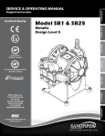
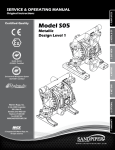
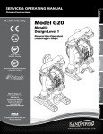
SERVICE & OPERATING MANUAL
Original Instructions
Model 41-818831
Conductive Acetal Ball Valve Pump
II 2 G c T5
G c T5
IIII 3/2
2GD
T5
II 2 D c T100°c
Table of Contents
Engineering Data and Temperature Limitations........................................................1
Air Valve Assembly Drawing....................................................................................10
Warranty Information.................................................................................................1
Air Valve Assembly Parts List..................................................................................10
Performance Curve...................................................................................................2
Air Valve Servicing...................................................................................................11
Dimensions................................................................................................................3
Pilot Valve Servicing................................................................................................12
Metric Dimensions.....................................................................................................3
Intermediate Assembly Drawing and Servicing.......................................................13
Principle of Pump Operation.....................................................................................4
Check Valve Drawing..............................................................................................14
Installation and Start-up............................................................................................4
Check Valve Servicing.............................................................................................14
Air Supply..................................................................................................................4
Diaphragm Service Drawing, with Overlay..............................................................15
Air Valve Lubrication..................................................................................................4
Diaphragm Servicing...............................................................................................16
Air Line Moisture.......................................................................................................4
Overlay Diaphragm Servicing .................................................................................16
Air Inlet and Priming..................................................................................................4
Pumping Hazardous Liquids...................................................................................17
Between Uses...........................................................................................................4
Converting the Pump for Piping the Exhaust Air.....................................................17
Troubleshooting ........................................................................................................5
Exhaust Conversion Drawing..................................................................................17
Important Safety Information.....................................................................................6
Converted Exhaust Illustration................................................................................17
Composite Repair Parts Drawing..............................................................................8
Grounding the Pump...............................................................................................18
Overlay Option Drawing, Muffler Option Drawing.....................................................8
EC Declaration of Conformity - Machinery..............................................................19
Available Service and Conversion Kits......................................................................8
EC Declaration of Conformity - ATEX......................................................................20
Composite Repair Parts List......................................................................................9
Explanation of ATEX Certificate...............................................................................21
Binks • 195 International Blvd. • Glendale Heights, IL 60139 USA • Telephone: 1.800.99.BINKS, 630.237.5000
Toll Free Customer Service and Technical Support: 800-992-4657 • Toll Free Fax: 888-246-5732
Part Sheet 77-2995
Model 41-818831
Conductive Acetal
Ball Valve Pump
Air Operated
Double-Diaphragm Pump
II 2 G c T5
G c T5
IIII 3/2
2GD
T5
ENGINEERING, PERFORMANCE
& CONSTRUCTION DATA
II 2 D c T100°c
Intake/Discharge Pipe Size
1/2" NPT(Internal) or 1/2" BSPT (Tapered)
1" NPT(External) or 1" BSPT (Tapered)
Capacity
0 to 14 gallons per minute
(0 to 52 liters per minute)
Air Valve
No-lube, no-stall
design
Solids-Handling
Up to .125 in. (3mm)
CAUTION! Operating temperature limitations are as follows:
Materials
Heads Up To
100 psi or 231 ft. of water
(7 Kg/cm2 or 70 meters)
Displacement/Stroke
.014 Gallon / .053 liter
Operating Temperatures
Maximum*
Minimum*
General purpose, oil-resistant. Shows good solvent, oil, water and hydraulic fluid resistance. Should not be used with highly polar solvents like
acetone and MEK, ozone, chlorinated hydrocarbons and nitro hyrdrocarbons.
190° F
88° C
-10° F
-23° C
Chemically inert, virtually impervious. Very few chemicals are known to react chemically with PTFE- molten alkali metals, turbulent liquid or
gaseous fluorine and a few fluoro-chemicals such as chlorine trifluoride or oxygen difluoride which readily liberate free fluorine at elevated temperatures.
190° F
88° C
-20° F
-29° C
High tensile material with excellent abrasion resistance. A general purpose material with excellent resistance to most oils.
Injection molded thermoplastic elastomer with no fabric layer. Long mechanical flex life. Excellent abrasion resistance.
220° F
104° C
-35° F
-37° C
180° F
82° C
-35° F
-37° C
275° F
135° C
-40° F
-40° C
CAUTION: Nonmetallic pumps and plastic components are not UV stabilized. Ultraviolet radiation can damage these parts and negatively affect material
properties. Do not expose to UV light for extended periods of time.
BINKS® pumps are designed to be powered only by compressed air.
Maximum and Minimum Temperatures are the limits for which these
materials can be operated. Temperatures coupled with pressure affect the
longevity of diaphragm pump components. Maximum life should not be
expected at the extreme limits of the temperature ranges.
Warranty Information
5-YEAR Limited Product Warranty
Binks® manufacturing warrants to the original end-use purchaser that no product sold by Binks shall fail under normal use and service
due to a defect in material or workmanship within five years from the date of shipment from Binks factory.
See complete warranty at www.binks.com
B41-818831conductiveacetal-rev0113
Model 41-818831 Conductive Acetal Ball Valve Pump Page 1
Performance based on the following: elastomer fitted pump, flooded suction, water at ambient conditions.
The use of other materials and varying hydraulic conditions may result in deviations in excess of 5%.
PSI
2.5 (4.3)
5 (8.5)
90
80
HEAD
5
4
80
70
60
2
0
40
PS
I (5
.44
ar)
Bar
15 (25.5)
)
.08 B
2.72 Ba
20 PSI
10
r)
(1.36 B
0
0
B41-818831conductiveacetal-rev0113
30
25
20
15
10
5
9.1
7.6
6
4.5
3
1.5
ar)
40 PSI (
30
0
.8 B
SI (4
20
1
10 (17)
I (6
60 P
50
3
PS
METERS
6
100
NPSHR
7 100
FEET
BAR
Performance Curve: BINKS Model 41-818831 Conductive Acetal
ar) Air Inle
t Pressure
2
4
10
6
8
10
U.S. Gallons per minute
20
30
Liters per minute
CAPACITY
40
12
14
50
Model 41-818831 Conductive Acetal Ball Valve Pump Page 2
Dimensions: BINKS Model 41-818831 Conductive Acetal
Dimensions in inches (metric dimensions in brackets). Dimensional Tolerance .125" (3mm).
DISCHARGE PORT
1/2" NPT (INTERNAL)
1" NPT (EXTERNAL)
10.11 257
7.46 189
(ALSO AVAILABLE IN BSP TAPERED)
3.09 78
1.75 44
MANIFOLD CAN ROTATE 90
FROM VERTICAL CENTERLINE
AIR INLET
1/4 FNPT
11.54 293
9.79 249
5.46 139
1.42 36
SUCTION PORT
1/2" NPT (INTERNAL)
1" NPT (EXTERNAL)
STANDARD INTEGRAL MUFFLER
1.75 44
.07 2
(ALSO AVAILABLE IN BSP TAPERED)
6.09 155
4X .36 9
MTG. SLOT
CONDUCTIVE ACETAL
DIMENSIONAL TOLERANCE = .125 [3mm]
4.75 121
B41-818831conductiveacetal-rev0113
Model 41-818831 Conductive Acetal Ball Valve Pump Page 3
Principle of Pump Operation
This ball type check valve pump
is powered by compressed air and is
a 1:1 ratio design. The inner side of
one diaphragm chamber is alternately
pressurized while simultaneously
exhausting the other inner chamber.
This causes the diaphragms, which
are connected by a common rod
secured by plates to the centers of the
diaphragms, to move in a reciprocating
action. (As one diaphragm performs the
discharge stroke the other diaphragm is
pulled to perform the suction stroke in
the opposite chamber.) Air pressure is
applied over the entire inner surface of
the diaphragm while liquid is discharged
from the opposite side of the diaphragm.
The diaphragm operates in a balanced
condition during the discharge stroke
which allows the pump to be operated
at discharge heads over 200 feet (61
meters) of water.
For maximum diaphragm life, keep
the pump as close to the liquid being
pumped as possible. Positive suction
head in excess of 10 feet of liquid
(3.048 meters) may require a back
pressure regulating device to maximize
diaphragm life.
Alternate pressurizing and
exhausting of the diaphragm chamber
is performed by an externally mounted,
pilot operated, four way spool type
air distribution valve. When the spool
shifts to one end of the valve body, inlet
pressure is applied to one diaphragm
chamber and the other diaphragm
chamber exhausts. When the spool
shifts to the opposite end of the valve
B41-818831conductiveacetal-rev0113
body, the pressure to the chambers
is reversed. The air distribution valve
spool is moved by a internal pilot valve
which alternately pressurizes one end
of the air distribution valve spool while
exhausting the other end. The pilot valve
is shifted at each end of the diaphragm
stroke when a actuator plunger is
contacted by the diaphragm plate. This
actuator plunger then pushes the end
of the pilot valve spool into position to
activate the air distribution valve.
The chambers are connected with
manifolds with a suction and discharge
check valve for each chamber,
maintaining flow in one direction
through the pump.
Installation And Start-up
Locate the pump as close to the
product being pumped as possible.
Keep the suction line length and
number of fittings to a minimum. Do not
reduce the suction line diameter.
For installations of rigid piping,
short sections of flexible hose should
be installed between the pump
and the piping. The flexible hose
reduces vibration and strain to the
pumping system. A surge suppressor
is recommended to further reduce
pulsation in flow.
Air Supply
Air supply pressure cannot exceed
125 psi (8.6 bar). Connect the pump
air inlet to an air supply of sufficient
capacity and pressure required for
desired performance. When the air
supply line is solid piping, use a short
length of flexible hose not less than
1/2" (13mm) in diameter between
the pump and the piping to reduce
strain to the piping. The weight of the
air supply line, regulators and filters
must be supported by some means
other than the air inlet cap. Failure to
provide support for the piping may result
in damage to the pump. A pressure
regulating valve should be installed
to insure air supply pressure does not
exceed recommended limits.
Air Valve Lubrication
The air distribution valve and the
pilot valve are designed to operate
WITHOUT lubrication. This is the
preferred mode of operation. There may
be instances of personal preference or
poor quality air supplies when lubrication
of the compressed air supply is required.
The pump air system will operate with
properly lubricated compressed air
supply. Proper lubrication requires
the use of an air line lubricator set
to deliver one drop of SAE 10 nondetergent oil for every 20 SCFM (9.4
liters/sec.) of air the pump consumes
at the point of operation. Consult the
pump’s published Performance Curve
to determine this.
and alleviates the icing or freezing
problems.
Air Inlet And Priming
To start the pump, open the air valve
approximately 1/2" to 3/4" turn. After
the pump primes, the air valve can be
opened to increase air flow as desired.
If opening the valve increases cycling
rate, but does not increase the rate of
flow, cavitation has occurred. The valve
should be closed slightly to obtain the
most efficient air flow to pump flow ratio.
Between Uses
When the pump is used for materials
that tend to settle out or solidify when
not in motion, the pump should be
flushed after each use to prevent
damage. (Product remaining in the
pump between uses could dry out or
settle out. This could cause problems
with the diaphragms and check valves
at restart.) In freezing temperatures
the pump must be completely drained
between uses in all cases.
Air Line Moisture
Water in the compressed air supply
can create problems such as icing or
freezing of the exhaust air, causing
the pump to cycle erratically or stop
operating. Water in the air supply can
be reduced by using a point-of-use
air dryer to supplement the user’s air
drying equipment. This device removes
water from the compressed air supply
Model 41-818831 Conductive Acetal Ball Valve Pump Page 4
Troubleshooting
Possible Symptoms:
• Pump will not cycle.
• Pump cycles, but produces no flow.
• Pump cycles, but flow rate is
unsatisfactory.
• Pump cycle seems unbalanced.
• Pump cycle seems to produce
excessive vibration.
What to Check: Excessive suction lift
in system.
Corrective Action: For lifts exceeding
20 feet (6 meters), filling the pumping
chambers with liquid will prime the
pump in most cases.
What to Check: Excessive flooded
suction in system.
Corrective Action: For flooded
conditions exceeding 10 feet (3 meters)
of liquid, install a back pressure device.
What to Check: System head exceeds
air supply pressure.
Corrective Action: Increase the
inlet air pressure to the pump. Most
diaphragm pumps are designed for 1:1
pressure ratio at zero flow.
What to Check: Air supply pressure or
volume exceeds system head.
Corrective Action: Decrease inlet
air pressure and volume to the pump
as calculated on the published
PERFORMANCE CURVE. Pump is
cavitating the fluid by fast cycling.
B41-818831conductiveacetal-rev0113
What to Check: Undersized suction
line.
Corrective Action: Meet or exceed
pump connection recommendations
shown on the DIMENSIONAL
DRAWING.
What to Check: Restricted or
undersized air line.
Corrective Action: Install a larger
air line and connection. Refer to air
inlet recommendations shown in your
pump’s SERVICE MANUAL.
What to Check: Check, the Externally
Serviceable Air Distribution System of
the pump.
Corrective Action: Disassemble and
inspect the main air distribution valve,
pilot valve and pilot valve actuators.
Refer to the parts drawing and air valve
section of the SERVICE MANUAL.
Check for clogged discharge or closed
valve before reassembly.
What to Check: Rigid pipe connections
to pump.
Corrective Action: Install flexible
connectors and a Surge Suppressor.
What to Check: Blocked air exhaust
muffler.
Corrective Action: Remove muffler
screen, clean or de-ice and reinstall.
Refer to the Air Exhaust section of your
pump SERVICE MANUAL.
What to Check: Pumped fluid in air
exhaust muffler.
Corrective Action: Disassemble pump
chambers. Inspect for diaphragm rupture
or loose diaphragm plate assembly. Refer
to the Diaphragm Replacement section
of your pump SERVICE MANUAL.
What to Check: Suction side air leakage
or air in product.
Corrective Action: Visually inspect
all suction side gaskets and pipe
connections.
What to Check: Obstructed check
valve.
Corrective Action: Disassemble the wet
end of the pump and manually dislodge
obstruction in the check valve pocket.
Refer to the Check Valve section of
the pump SERVICE MANUAL for
disassembly instructions.
What to Check: Blocked pumping
chamber.
Corrective Action: Disassemble
and inspect the wetted chambers
of the pump. Remove or flush any
obstructions. Refer to the pump
SERVICE MANUAL for disassembly
instructions.
What to Check: Entrained air or vapor
lock in one or both pumping chambers.
Corrective Action: Purge chambers
through tapped chamber vent plugs.
PURGING THE CHAMBERS OF AIR
CAN BE DANGEROUS! Contact BINKS
before performing this procedure. Any
model with top-ported discharge will
reduce or eliminate problems with
entrained air.
What to Check: Worn or misaligned
check valve or check valve seat.
Corrective Action: Inspect check
valves and seats for wear and proper
seating. Replace if necessary. Refer
to Check Valve section of the pump
SERVICE MANUAL for disassembly
instructions.
What to Check: Blocked suction line.
Corrective Action: Remove or flush
obstruction. Check and clear all suction
screens and strainers.
What to Check: Blocked discharge line.
Corrective Action: Check for obstruction
or closed discharge line valves.
Model 41-818831 Conductive Acetal Ball Valve Pump Page 5
Recycling
Many components of Conductive
Acetal AODD pumps are made of
recyclable materials (see chart on
page 10 for material specifications).
We encourage pump users to recycle
worn out parts and pumps whenever
possible, after any hazardous pumped
fluids are thoroughly flushed.
Important Safety
Information
IMPORTANT
Read these safety warnings
and instructions in this
manual completely, before
installation and start-up
of the pump. It is the
responsibility of the purchaser to retain this
manual for reference. Failure to comply with
the recommendations stated in this manual will
damage the pump, and void factory warranty.
CAUTION
Before pump operation,
inspect all gasketed
fasteners for looseness
caused by gasket creep. Retorque loose fasteners to
prevent leakage. Follow recommended torques
stated in this manual.
WARNING
Take action to prevent static
sparking. Fire or explosion
can result, especially when
handling flammable liquids.
The pump, piping, valves,
containers or other miscellaneous equipment
must be grounded. (See Page 20)
WARNING
This pump is pressurized
internally with air pressure
during operation. Always
make certain that all bolting
is in good condition and
that all of the correct
bolting is reinstalled during assembly.
WARNING
When used for toxic or
aggressive fluids, the pump
should always be flushed
clean prior to disassembly.
WARNING
WARNING
Before maintenance or
repair, shut off the compressed air line, bleed the
pressure, and disconnect
the air line from the pump.
The discharge line may be
pressurized and must be bled of its pressure.
WARNING
In the event of diaphragm
rupture, pumped material
may enter the air end of the
pump, and be discharged
into the atmosphere. If
pumping a product which is hazardous or toxic,
the air exhaust must be piped to an appropriate
area for safe disposition.
B41-818831conductiveacetal-rev0113
Before doing any
maintenance on the pump,
be certain all pressure is
completely vented from the
pump, suction, discharge,
piping, and all other openings and connections.
Be certain the air supply is locked out or made
non‑operational, so that it cannot be started
while work is being done on the pump. Be
certain that approved eye protection and
protective clothing are worn all times in the
vicinity of the pump. Failure to follow these
recommendations may result in serious injury
or death.
WARNING
Airborne particles and loud
noise hazards.
Wear ear and eye protection.
Model 41-818831 Conductive Acetal Ball Valve Pump Page 6
B41-818831conductiveacetal-rev0113
Model 41-818831 Conductive Acetal Ball Valve Pump Page 7
Composite Repair Parts Drawing
11
8
19
Available Service Kits
41-718850 AIR MOTOR REPAIR KIT
O-rings, Gaskets, Bumpers, Bushings,
Retainers, and Seals
41-718861 DIAPHRAGM KIT
Santoprene Backup Diaphragm,
PTFE Overlay Diaphragms,
PTFE Manifold O-rings, and
PTFE Seals for metal
check valve seats
41-718854 BALL AND SEAT KIT
316 Stainless Steel Check Balls,
316 Stainless Steel Check Valve Seats
PTFE Seals for metal
check valve seats
3
20
9
32
22
9
32
21
25
7
10
29
31
4
12
10
28
1
17
10
24
35
30
9
35
6
2
13
27
33
10
15
10
24
10
2
24
35
33
32
35
16
22
32
5
24
9
10
B41-818831conductiveacetal-rev0113
Model 41-818831 Conductive Acetal Ball Valve Pump Page 8
Composite Repair Parts List
Item
1
2
3
4
5
6
7
8
9
10
11
12
13
15
16
17
19
Description
Qty
Air Valve Assembly
1
Ball, Check
4
Pilot Valve Assembly 1
Bracket, Intermediate 1
Bracket, Mounting
2
Bumper, Diaphragm 2
Bushing, Plunger
2
Cap, Air Inlet
1
Capscrew, Flanged 5/16-18 X 1.00
12
Capscrew, Flanged 5/16-18 X 1.25
36
Capscrew, Flanged 1/4-20 X 1.50
4
Capscrew, Flanged 1/4-20 X .75
4
Chamber, Outer
2
Diaphragm, One-Piece Bonded PTFE
Elbow, Suction
2
Elbow, Discharge
2
Gasket, Air Inlet
1
Item
2
20
21
22
24
25
27
28
29
30
31
32
33
34
35
Description
Qty
Gasket, Pilot Valve
1
Gasket, Air Valve
1
Manifold, NPT
2
Manifold, BSPT (Tapered)2
Nut, Flanged 5/16-18
24
O.ring
2
Plate, Inner Diaphragm
2
Plunger, Actuator
2
Ring, Retaining
2
Rod, Diaphragm 1
Seal, Diaphragm Rod
2
Seal, Manifold
4
Seat, Check Valve
4
Grounding Cable
1
Seal, Metal Check Value Seats
8
LEGEND:
= Items contained within 41-718850 Air Motor Repair Kits
= Items contained within 41-718861 Diaphragm Kits
= Items contained within 41-718854 Ball and Seat Kits
B41-818831conductiveacetal-rev0113
Model 41-818831 Conductive Acetal Ball Valve Pump Page 9
Air DistributionValve Assembly Drawing
MAIN Air Valve ASSEMBLY Parts List
Item
Description
1
Valve Assembly
1-A
Sleeve and Spool Set 1-B
Valve Body
1-CBumper
1-D
End Cap
1-E
Hex Flange Capscrew 1/4-20 x .75
1-FO-ring
1-G
Muffler
1-H Muffler Cap
1-I Machine Screw 6-32 x 1.25
1-I
1-H
1-F
1-F
Qty
1
1
1
2
2
8
4
1
1
4
LEGEND:
1-G
1-E
= Items contained within 41-718850 Air Motor Repair Kits
1-C
1-D
1-A
1-C
1-D
1-E
1-B
1-F
1-F
B41-818831conductiveacetal-rev0113
Model 41-818831 Conductive Acetal Ball Valve Pump Page 10
A IR D IS T RI B U T I O N
VA LV E
SERVICING
To service the air valve first shut
off the compressed air, bleed pressure
from the pump, and disconnect the air
supply line from the pump.
Step #1: See COMPOSITE REPAIR
PARTS DRAWING.
Using a 3/8" wrench or socket,
remove the four hex capscrews (items
11). Remove the air valve assembly
from the pump.
Remove and inspect gasket (item
22) for cracks or damage. Replace
gasket if needed.
Step #2: Disassembly of the air valve.
Using a 3/8" wrench or socket,
remove the eight hex capscrews
(items 1-E) that fasten the end caps to
the valve body. Next remove the two
end caps (items 1-D). Inspect the two
o-rings (items 1-F) on each end cap for
damage or wear. Replace the o-rings
as needed.
Remove the bumpers (items 1-C).
Inspect the bumpers for damage or
wear. Replace the bumpers as needed.
Remove the spool (part of item
1-A) from the sleeve. Be careful not to
scratch or damage the outer diameter
of the spool. Wipe spool with a soft cloth
and inspect for scratches or wear.
Inspect the inner diameter of the
sleeve (part of item 1-A) for dirt,
B41-818831conductiveacetal-rev0113
scratches, or other contaminants. Remove
the sleeve if needed and replace with
a new sleeve and spool set (item 1-A).
Step #3: Reassembly of the air valve.
Install one bumper (item 1-C) and
one end cap (item 1-D), with two o-rings
(items 1-F), and fasten with four hex
capscrews (items 1-E) to the valve body
(item 1-B). Align hole in end cap with roll
pin on valve body.
Remove the new sleeve an spool
set (item 1-A) from the plastic bag.
Carefully remove the spool from the
sleeve. Install the six o-rings (item 1-F)
into the six grooves on the sleeve. Apply
a light coating of grease to the o-rings
before installing the sleeve into the
valve body (item 1-B), align the slots
in the sleeve with the slots in the valve
body. Insert the spool into the sleeve.
Be careful not to scratch or damage
the spool during installation. Install the
remaining bumper and end cap (with
o-rings), and fasten with the remaining
hex capscrews. Align hole in end cap
with roll pin on valve body.
Fasten the air valve assembly (item
1) and gasket to the pump.Connect the
air line to the pump. The pump is now
ready for operation.
IMPORTANT
Read these instructions
c o m p l e t e l y, b e f o r e
installation and start-up.
It is the responsibility of
the purchaser to retain
this manual for reference. Failure to
comply with the recommendations stated
in this manual will damage the pump, and
void factory warranty.
Model 41-818831 Conductive Acetal Ball Valve Pump Page 11
Pilot Valve Assembly Drawing
Pilot Valve Assembly Parts List
For Models Equipped with Aluminum Midsections
ItemDescription
Qty
3
3-A
3-B
3-C
3-D
3-E
3-F
Pilot Valve Assembly
Valve Body
Sleeve (With O-Rings)
O-Ring (Sleeve)
Spool (With O-Rings)
O-Ring (Spool)
Retaining Ring
1
1
1
6
1
3
1
LEGEND:
= Items contained within 41-718850 Air Motor Repair Kits
B41-818831conductiveacetal-rev0113
Model 41-818831 Conductive Acetal Ball Valve Pump Page 12
Intermediate Assembly Drawing
ACTUATOR PLUNGER Servicing
To service the actuator plunger first
shut off the compressed air supply,
bleed the pressure from the pump, and
disconnect the air supply line from the
pump.
29
25
7
Step #1: See pump assembly
drawing.
Using a 3/8 " wrench or socket,
remove the four capscrews (items 11).
Remove the air inlet cap (item 8) and
air inlet gasket (item 19). The pilot valve
assembly (item 3) can now be removed.
28
28
25
29
Intermediate Repair Parts List
ItemDescription
4
Bracket, Intermediate 7
Bushing, Plunger
25O-Ring
28
Plunger, Actuator
29
Ring, Retaining*
Qty
1
2
2
2
2
*Note: It is recommended that when plunger components are serviced,
new retaining rings be installed.
LEGEND:
= Items contained within 41-718850 Air Motor Repair Kits
B41-818831conductiveacetal-rev0113
Step #2: Servicing the actuator
plungers.
See pump assembly drawing.
The actuator plungers (items 28)
can be reached through the stem cavity
of the pilot valve in the intermediate
bracket (item 4). To service bushings,
o-rings and retaining rings, see
Intermediate Drawing.
Remove the plungers (items 28) from
the bushings (item 7) in each end of the
intermediate cavity. Inspect for wear or
damage. Replace plunger as needed.
Apply a light coating of grease to each
o-ring and re-install the plungers in to
the bushings. Push the plungers in as
far as they will go.
Step #3: Re-install the pilot valve
assembly into the intermediate
assembly.
Be careful to align the ends of
the stem between the plungers when
inserting the stem of the pilot valve into
the cavity of the intermediate.
Re-install the gasket (item 19),
air inlet cap (item 8) and capscrews
(items 11).
Connect the air supply to the pump.
The pump is now ready for operation.
Plunger Bushing, O-ring, And
Retaining Ring Servicing
To service the plunger bushing
components first remove the two
retaining rings (items 29) using a
small flat screwdriver. *Note: It is
recommended that new retaining rings
be installed.
Next remove the two plunger
bushings (items 7). Inspect the bushings
for wear or scratches. Replace the
bushings as necessary.
Inspect the two o-rings (25) for cuts
and/or wear.
IMPORTANT
Read these instructions
completely, before installation and start-up.
It is the responsibility of
the purchaser to retain
this manual for reference. Failure to
comply with the recommendations stated
in this manual will damage the pump, and
void factory warranty.
Model 41-818831 Conductive Acetal Ball Valve Pump Page 13
Check Ball Valve Drawing
9
10
17
24
13
2
33
35
B41-818831conductiveacetal-rev0113
35
Modular Check Ball Valve
Servicing
Before servicing the check valves,
first shut off the suction line and then
the discharge line to the pump. Next,
shut off the compressed air supply,
bleed air pressure from the pump, and
disconnect the air supply line from
the pump. Drain any remaining fluid
from the pump. The pump can now be
removed for service.
To access the modular check valve,
remove the elbows (items 16 and 17
from pump composite repair parts
drawing). Use a 1/2" wrench or socket
to remove the fasteners. Once the
elbows are removed, the modular check
valves can be seen in the cavities of the
outer chamber (items 13).
Inspect the check balls (items 2) for
wear, abrasion, or cuts on the spherical
surface. The check valve seats (items
33) should be inspected for cuts,
abrasive wear, or embedded material
on the surfaces of both the external
and internal chambers. The spherical
surface of the check balls must seat
flush to the surface of the inner chamfer
on the check valve seats for the pump to
operate to peak efficiency. Replace any
worn or damaged parts as necessary.
IMPORTANT
Read these instructions
completely, before installation and start-up.
It is the responsibility of
the purchaser to retain
this manual for reference. Failure to
comply with the recommendations stated
in this manual will damage the pump, and
void factory warranty.
Re-assemble the check valve
Place a check ball (item 2) in the
ball cage of either the discharge elbow
or the outer chamber. Install a check
valve seat in the counter on each end
of the chamber. Refasten the elbows to
the chamber.
Model 41-818831 Conductive Acetal Ball Valve Pump Page 14
Diaphragm Service Drawing, with Overlay
30
10
6
10
27
24
24
14
13
10
10
9
B41-818831conductiveacetal-rev0113
15
14
Model 41-818831 Conductive Acetal Ball Valve Pump Page 15
Diaphragm Servicing
To service the diaphragms first
shut off the suction, then shut off the
discharge lines to the pump. Shut
off the compressed air supply, bleed
the pressure from the pump, and
disconnect the air supply line from the
pump. Drain any remaining liquid from
the pump.
Step #1: See the pump composite
repair parts drawing, and the diaphragm
servicing illustration.
Using a 1/2" wrench or socket,
remove the 16 capscrews (items 9 &
10), and flanged nuts that fasten the
elbows (items 16 and 17) to the outer
chambers (items 13). Remove the
elbows with the manifolds and spacers
attached.
Step #2: Removing the outer
chambers.
Using a 1/2" wrench or socket,
remove the 16 capscrews (items 9
and 10), and flanged nuts that fasten
the outer chambers, diaphragms, and
intermediate (item 4) together.
Step #3: Remove the diaphragm by
turning counterclockwise.
Inspect the diaphragm (item 14)
for cuts, punctures, abrasive wear
or chemical attack. Replace the
diaphragms if necessary.
Step #4: Installing the diaphragms.
Make sure the bumper (item 6) is
installed over the diaphragm rod.
Thread the stud of the one diaphragm
clockwise into the tapped hole at the
end of the diaphragm rod (item 30) until
the inner diaphragm plate is flush to the
end of the rod. Insert rod into pump.
Align the bolt holes in the diaphragm
with the bolt pattern in the intermediate
(item 4).
Fasten the outer chamber (item
13) to the pump, using the capscrews
(items 9 and 10) and flanged nuts.
On the opposite side of the pump,
pull the diaphragm rod out as far as
possible. Make sure the bumper (item
6) is installed over the diaphragm rod.
Thread the stud of the remaining
diaphragm assembly clockwise into the
tapped hole at the end of the diaphragm
rod (item 30) as far as possible and
still allow for alignment of the bolt
holes in the diaphragm with the bolt
pattern in the inner chamber. Install
diaphragms with convolutions facing
towards center of pump. See sectional
view on previous page.
Fasten the remaining outer chamber
(item 13) to the pump, using the
capscrews (items 9 and 10) and flanged
nuts.
Step #5: Re-install the elbow/
spacer/manifold assemblies to the
pump, using the capscrews (items 9 &
10) and flanged nuts.
The pump is now ready to be
re-installed, connected and returned to
operation.
IMPORTANT
Read these instructions
completely, before installation and start-up.
It is the responsibility of
the purchaser to retain
this manual for reference. Failure to
comply with the recommendations stated
in this manual will damage the pump, and
void factory warranty.
B41-818831conductiveacetal-rev0113
Model 41-818831 Conductive Acetal Ball Valve Pump Page 16
Pumping Hazardous Liquids
When a diaphragm fails, the pumped
liquid or fumes enter the air end of the
pump. Fumes are exhausted into
the surrounding environment. When
pumping hazardous or toxic materials,
the exhaust air must be piped to an
appropriate area for safe disposal. See
illustration #1 at right.
This pump can be submerged if
the pump materials of construction
are compatible with the liquid being
pumped. The air exhaust must be
piped above the liquid level. See
illustration #2 at right. Piping used for
the air exhaust must not be smaller
than 1/2" (2.54 cm) diameter. Reducing
the pipe size will restrict air flow and
reduce pump performance. When the
pumped product source is at a higher
level than the pump (flooded suction
condition), pipe the exhaust higher than
the product source to prevent siphoning
spills. See illustration #3 at right.
Converting the pump for
piping the exhaust air
The following steps are necessary
to convert the pump to pipe the exhaust
air away from the pump.
The air distribution valve body has
3/8" NPT threads for installation of
metal muffler or piped exhaust.
Important Installation Note:
The manufacturer recommends
installing a conductive flexible hose or
connection between the pump and any
rigid plumbing. This reduces stresses
on the molded plastic threads of the
air exhaust port. Failure to do so may
result in damage to the air distribution
valve body.
Any piping or hose connected to
the pump’s air exhaust port must be
groundable and physically supported.
Failure to support these connections
could also result in damage to the air
distribution valve body.
Converted Exhaust Illustration
PUMP INSTALLATION AREA
SAFE AIR
EXHAUST
DISPOSAL
AREA
1" DIAMETER AIR
EXHAUST PIPING
MUFFLER
Illustration #1
MUFFLER
LIQUID
LEVEL
1
1" DIAMETER AIR
EXHAUST PIPING
SUCTION
LINE
Illustration #2
MUFFLER
LIQUID
LEVEL
1" DIAMETER AIR
EXHAUST PIPING
SUCTION
LINE
Illustration #3
B41-818831conductiveacetal-rev0113
Model 41-818831 Conductive Acetal Ball Valve Pump Page 17
Grounding The Pump
One eyelet end is fastened to the pump hardware.
The other end is installed to a true earth ground.
This Ground Strap (Item 34) is shipped with the eyelet
end fastened to the pump hardware.
To reduce the risk of static electrical sparking, this pump
must be grounded. Check the local electrical code for
detailed grounding instruction and the type of equipment
required.
WARNING
Take action to prevent static
sparking. Fire or explosion can
result, especially when handling
flammable liquids. The pump,
piping, valves, containers or
other miscellaneous equipment
must be grounded.
B41-818831conductiveacetal-rev0113
Model 41-818831 Conductive Acetal Ball Valve Pump Page 18
Declaration of Conformity
BINKS, 195 International Blvd, Glendale Heights, IL 60139
certifies that BINKS models: 41-818810, 41-818820, 41-818822, 41-818830,
41-818823, 41-818831 and 41-818836 Air-Operated Double Diaphragm Pumps comply with the
European Community Directive 2006/42/EC on Machinery, according to Annex VIII.
This product has used Harmonized Standard EN809:1998+A1:2009, Pumps and
Pump Units for Liquids - Common Safety Requirements, to verify conformance.
Signature of authorized person
Charles W. McCulloch
Printed name of authorized person
Revision Level: E
June 8, 2012
Date of issue
Engineering Manager
Title
January 3, 2013
Date of revision
EC Declaration of Conformity
In accordance with ATEX Directive 94/9/EC,
Equipment intended for use in potentially explosive environments.
Manufacturer: BINKS
195 International Blvd, Glendale Heights, IL 60139
AODD Pumps
For Type Examination Designations, see page 2 (back)
Applicable Standard:
EN13463-1: 2001,
EN13463-5: 2003
KEMA Quality B.V.
Utrechtseweg 310
6812 AR Arnhem, The Netherlands
DATE/APPROVAL/TITLE:
June 11, 2012
Charles W. McCulloch, Engineering Manager
EC Declaration of Conformity
ATEX Summary of Markings
Type
BINKS Models:
41-818810
41-818820
41-818822
41-818830
41-818823
41-818836
Marking
II 2 G c T5
II 3/2 G c T5
II 2 D c T100oC
Type Certificate No. Pumps: KEMA 09ATEX0072 X
Listed In
KEMA 09ATEX0072 X KEMA 09ATEX0072 X
CE
KEMA 09ATEX0072 X
KEMA 09ATEX0072 X