1
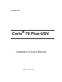
Coramex S.A. Corix 70 Plus-USV Installation & User’s Manual Release 1.2 May 2009 CONTENTS 1. Introduction Section …………………………………………………………… 1.0 2. Safety Information …………………………………………………… Warnings …………………………………………………………………… 2.0 2.1 3. Description …………………………………………………………… Identification Labels …………………………………………………… Equipment Parts …………………………………………………………… Configurations …………………………………………………………… 3.0 3.1 3.2 3.3 4. Technical Features 5. Pre-Installation 6. Electrical Features ……………………………………………………. 4.0 ……………………………………………………….. 5.0 ……………………………………………………. 5.1 7. Installation ……………………………………………………………. Corix 70 Plus-USV-WM (Wall Mount) …………………………………... Installation of options for Wall Mount model …………………………. Corix 70 Plus-USV-MM (Mobile Stand) ……………………………. Corix 70 Plus-USV-PS (Portable Stand) ……………………………. Folding and Extension Arm assembly (Wall Mount)…………………… Folding Arm assembly (Mobile Stand) ………………………………….. Folding Arm assembly (Portable Stand) ………………………………… Tubehead assembly ……………………………………………………….. Electrical connections to the Control Panel …………………………….. Optional wiring to the Control Panel ……………………………………… 6.0 6.2 6.3 6.4 6.5 6.6 6.7 6.8 7.0 8.0 8.3 8. Final functioning tests ……………………………………………………… 8.4 9. Control Panel operating instructions and system operation…………... 9.0 10. Protection against radiation ………………………………………………. 10.0 11. Checks and corrections of possible faults in dental radiography.. ……. 11.0 12. Maintenance ……………………………………………………………….. 12.0 13. Environmental risks and disposal ……………………………………….. 13.0 14. Drawings and Electrical Schemes…………………………………… 14.0 2 Corix 70 Plus - USV Installation & User´s Manual 1.0 INTRODUCTION Corix 70 Plus-USV, manufactured by Coramex S.A., performs high quality intra-oral radiographs, ensured by the repeatability of examination combined with reduced exposure times and a small focal spot. Corix 70 Plus-USV has a new Control Panel with a graphic LCD display, with an array of flexible sub-menu options and an easy pre-set exposure timer. This manual is intended to assist the user and installer in the safe and efficient operation and installation of the equipment described. 2.0 SAFETY INFORMATION This manual provides all the necessary information for the correct handling of the equipment as well as warnings related to risks associated to Xray generators. Coramex S.A. shall not be responsible for: Any use of the equipment different from what it has been designed for. Any damage to the equipment, the operator or the patient caused by incorrect installation and maintenance not compliant with the procedures contained in the relevant user’s and installation manuals, or by incorrect operation techniques. Any mechanical and/or electrical changes caused during or after installation, different from those reported in the service manual. Any expenses related to the eventual disposal of the equipment or parts. 2.1 Warnings The equipment must be used in compliance with the procedures contained in the present manual and shall never be used for purposes other than those it was designed for. Only qualified service personnel are allowed to perform technical interventions on the equipment and to remove the tubehead from its support and access the internal components. There is risk of injury if proper procedures are not followed. The user bears legal responsibility related to the possession, installation and use of the equipment. Corix 70 Plus-USV is a dental imaging device and must be used only under the supervision of qualified staff with knowledge in the field of protection against radiation. 3 Corix 70 Plus - USV Installation & User´s Manual To protect the patient from X-ray, radiation protection accessories, such as standard leaded aprons must be used. The Tubehead cover or the relevant Beam Centering Device should not be touched during X-ray emission. No objects (i.e., lead aprons) should be hung from the extension arms. The film or the digital sensor must be introduced in the patient’s mouth either manually or by means of the relevant holders; it must never be held by the operator, and only the patient may hold it if required. Parts of the equipment that may be in contact with the patient must be regularly cleaned following the instruction provided in this manual. The equipment is not designed to be used in the presence of flammable anesthetics, oxygen or nitrous oxide. Before performing any maintenance intervention, the equipment must be disconnected from the input line voltage by means of the relevant circuit breaker. 4 Corix 70 Plus - USV Installation & User´s Manual 3.0 DESCRIPTION 3.1 Identification labels 5 Corix 70 Plus - USV Installation & User´s Manual 6 Corix 70 Plus - USV Installation & User´s Manual 7 Corix 70 Plus - USV Installation & User´s Manual 8 Corix 70 Plus - USV Installation & User´s Manual 3.2 Equipment Parts A set of different models of the complete extraoral dental X-Ray device share the certified components listed Model Corix 70 Plus-USV-WM (Wall Mount) Common Part X-Ray Tube Housing Assembly Beam Limiting Device X-Ray Button, Standard Control Panel Cat. P500USV Cat. P501USV Cat. P507USV Cat. P506USV Particular Part Extension Arm, Standard (80cm) Extension Arm, Large (90cm) (optional) Extension Arm, Short (35cm) (optional) Remote X-Ray button Kit (optional) WM Folding Arm Wall Plate – Double stud Wall Plate – Single stud (optional) Cat. P503USV Cat. P504USV Cat. P505USV Cat. P514USV Cat. P502USV Cat. P510USV Cat. P511USV Model Corix 70 Plus-USV-MM (Mobile Stand) Common Part X-Ray Tube Housing Assembly Beam Limiting Device X-Ray Button, Standard Control Panel Cat. P500USV Cat. P501USV Cat. P507USV Cat. P506USV Particular Part MM Folding Arm Mobile Base Cat. P508USV Cat. P509USV Model Corix 70 Plus-USV-PS (Portable Stand) Common Part X-Ray Tube Housing Assembly Beam Limiting Device X-Ray Button, Standard Control Panel Cat. P500USV Cat. P501USV Cat. P507USV Cat. P506USV Particular Part PS Folding Arm Portable Base Cat. P512USV Cat. P513USV 9 Corix 70 Plus - USV Installation & User´s Manual 10 Corix 70 Plus - USV Installation & User´s Manual 11 Corix 70 Plus - USV Installation & User´s Manual 12 Corix 70 Plus - USV Installation & User´s Manual 13 Corix 70 Plus - USV Installation & User´s Manual 4.0 TECHNICAL FEATURES Technical Features Equipment Manufacturer Model Designation Class Rated Line Voltage Line Frequency Line Current Power Consumption Apparent Line Resistance Line Voltage Regulation Main Fuse X-Ray Control Part Designation Exposure Times Timer Accuracy Extraoral Source X-Ray Imaging System (General Purpose Dental) Coramex S.A. Lauro Villar 94-B México, D.F. 02440-México Corix 70 Plus-USV I type B 120VAC or 230VAC ± 10% 50/60Hz 10A @ 120VAC; 6A @ 230VAC 1.05 KW máx. 0.2 Ohms máx. @ 120VAC <= 3% 10 AF @ 120VAC; 6 AF @ 230VAC Control Panel with Microprocessor controlled Digital Timer, Safety Relay and Back-Up Timer P506USV (Control Panel with Main Terminals Device) Manual Time Selection from 0.03 s. to 3.00 s., in steps of 0.01s., plus 27 preset exposure times with automatic line voltage compensation (optional). Pre-heating time with 4 pre-selected values (*) 10% or ± 32 ms (whichever is greater) (*) Note: “Pre-heating time” is the time required by the tube to enable the correct radiation output. When selecting an exposure time, the display reads only the exposure time, but for timing testing purposes, the actual time is the “Exposure Time” plus the “Pre-heating Time” previously selected. 14 Corix 70 Plus - USV Installation & User´s Manual Tube Housing Assembly Extra-oral Diagnostic X-Ray generator and Beam Limiting Device Manufacturer Coramex S.A. Part Designation Rated Output Voltage P500USV 70 KVp ± 10% (Single phase, self rectifying) 8 mA ± 15% @ rated line voltage Rated Output Current Maximum Deviation of Output Current Total Filtration Transformer Insulation Cooling Radiation Leakage at 1 m. 4.5mA (over the voltage range) 2mm Al eq. Oil Bath Thermal Convection Cooling < 50 mR/h (Technical Factors 70KVp, 8mA, 1s.) Exposure Interval (Duty Cycle) 01:30 The minimum Exposure Interval between exposures (30 time units of cooling time for every time unit of exposure) is a Preset value in the Control Panel Unit X-Ray Tube Manufacturer Model Designation Focal Spot Inherent Filtration (Part of the Tube Housing Assembly) C.E.I., s.r.l. OX/70-P, or: OCX/70-G 0.8mm (IEC 336) 0.5mm Al eq. Beam Limiting Device Manufacturer Part Designation Minimum Focal Spot to Skin Distance (SSD) X-Ray Field Φ at Minimum SSD Coramex, S.A. P501USV 200mm 60mm 15 Corix 70 Plus - USV Installation & User´s Manual 16 Corix 70 Plus - USV Installation & User´s Manual 17 Corix 70 Plus - USV Installation & User´s Manual 4.1 AUTOMATIC EXPOSURE TIME COMPENSATION The X-Ray equipment includes a special characteristic which automatically compensates the exposure time when the line voltage is different from its nominal value. Line voltage variation affects the peak voltage applied to the Tubehead and this, in turn, affects the optimal density and contrast (visual characteristics) of the film or digital systems. With the automatic correction, it is possible to achieve the same optical quality of the image even with variations in line voltage. This automatic correction covers the range of ±10% of the nominal line voltage. To perform the time compensation, the Control Panel constantly takes samples of the line voltage. When the user chooses a pre-programmed selection, the exposure time corresponding to that selection is shown on the display. If there is a variation of the line voltage before the exposure had been taken, the Control Panel automatically calculates the corrected exposure time and shows it on the display. The value of the correction factor has been determined empirically by measuring the radiation dose against the line voltage, keeping the exposure time constant, and then determining the correction factor in the exposure time required to keep the radiation dose constant against the line voltage. The following graphic shows the relationship between the correction factor and the line voltage: It is possible to enable or disable the automatic line voltage compensation when taking pre-programmed selections. For manual exposure times, the line voltage compensation is always disabled. 18 Corix 70 Plus - USV Installation & User´s Manual 4.2 PRE-SET EXPOSURE TIMES The following table of pre-set exposure times in seconds shows the rated exposure time for a nominal line voltage of 120VAC (230VAC) and the final corrected exposure time, as a function of the line voltage correction factor and patient size, for the minimum 109VAC (207 VAC) and maximum 132VAC (253VAC) line voltage operating range. LINE VOLTAGE 108V (207V) 120V (230V) 132V (253V) 1.9 1.0 0.55 LINE VOLTAGE CORRECTION FACTOR PATIENTS SIZE LARGE SIZE MEDIUM SIZE SMALL SIZE LARGE SIZE MEDIUM SIZE SMALL SIZE LARGE SIZE MEDIUM SIZE SMALL SIZE UPPER JAW INCISOR 0.63 0.54 0.44 0.33 0.28 0.23 0.18 0.16 CUSPID 0.63 0.54 0.44 0.33 0.28 0.23 0.18 0.16 0.13 0.13 BICUSPID 0.76 0.65 0.53 0.40 0.34 0.28 0.22 0.19 0.15 MOLAR 0.85 0.72 0.59 0.45 0.38 0.31 0.25 0.21 0.17 INCISOR 0.45 0.38 0.31 0.24 0.21 0.17 0.13 0.11 0.09 CUSPID 0.45 0.38 0.31 0.24 0.21 0.17 0.13 0.11 0.09 BICUSPID 0.55 0.47 0.38 0.29 0.25 0.2 0.16 0.14 0.11 MOLAR 0.63 0.54 0.44 0.33 0.28 0.23 0.18 0.16 0.13 POSTERIOR BITEWING 0.63 0.54 0.44 0.33 0.28 0.23 0.18 0.16 0.13 LOWER JAW Notes: • • • • Suggested exposure times in seconds, for E type films. (For digital sensors, refer to section 9.0 “Control Panel Operating Instructions”, Film-Digital Sensor Submenu) Film speed: Factory pre-set for E type Films. Corrected exposure times rounded to the nearest 1/100 of second. This table does not show the added “Pre-heating time” selected for the x-ray tube. 4.3 PRACTICAL PROCEDURES FOR MEASURING TECHNICAL FACTORS KVp is defined as the high voltage value applied to the X-Ray tube after preheating time. KVp value should be measured by a non invasive instrument with an accuracy of over 2% to the nominal value. The anodic current value (mA) is defined as the average value of a steady state current through the X-Ray tube after pre-heating time. The anodic current value should be measured using a digital voltmeter. To do this, it is necessary to remove the Tubehead plastic covers. This operation must be performed only by a qualified technician. To take this measurement, the digital voltmeter should be selected on DC and read the voltage drop at the ends of a 1KΩ, 1%, assembled on the Tubehead. The relation of transformation is given by 1mA = 1V. Execute an exposure of at least 1s. 19 Corix 70 Plus - USV Installation & User´s Manual The time interval measured from the moment where the anodic peak current first exceeds 25% of the steady state to the moment it again reaches 25% when decreases is called the exposure time (t). When taking a measurement of this time, nominal line voltage should be selected, and a digital memory oscilloscope should be used to read the voltage drop across the 1KΩ resistor. The “pre-heating time” is the time taken for the anodic current to reach 25% of its steady state value. 4.4 MEASURING EXPOSURE TIMES The use of non-invasive equipment, when measuring functional parameters of XRay devices like exposure time, has led to introduce some interpretation issues. The root of these issues is due to the anodic current wave form which is represented in the next figure: IEC 60601-2-7 (1998) regulations reads: “in equipment where the filament is switched on and high voltage is applied simultaneously, the exposure time is calculated as the interval between the instant when the anodic current exceeds 25% of the nominal value and the instant when it goes below such value”. This method of measurement is defined as invasive because it requires that the anodic current be quantified through the voltage drop of a resistance inside the tubehead. The last figure shows the anodic current wave form for an exposure of 0.2s with a pre-heating time of 0.23s. It can be seen that the time named “Delta” 20 Corix 70 Plus - USV Installation & User´s Manual measured in the interval when the anodic current exceeds 25%, represents the actual exposure time (204.0ms). Although, non-invasive methods can be simpler to perform than the invasive methods, they may lead to errors which can be considerable when determining exposure time. Calculations of exposure time obtained by using non-invasive methods may lead to the conclusion that the unit timer is not accurate enough to meet the regulations (refer to section 4.3 Practical Procedures for Measuring Technical Factors). 5.0 PRE - INSTALLATION Proper planning prior to installation is required. There are three areas of concern before installation. 1) Mounting structure 2) Reach of the tubehead 3) Electrical connections ⇒ Warning Precise and safe installation, of the Corix 70 Plus – USV, is the full responsibility of the installer. Inappropriate installation of the equipment may cause it to drop from its support, resulting in damage to individuals and materials near its range. The manufacturer fully disclaims any responsibility expressed or implied by the actions of the installer. Different wall structures require different type of fasteners. It is the responsibility of the installer to use the appropriate fasteners. Always making sure that the installation is properly leveled. Judgment of wall sturdiness is left to the installer. Fixing bosses to be used for each type of wall are the following: ⇒ Concrete walls: expansion steel anchors ⇒ Wooden studs: self-threading screws ⇒ Hollow bricks: chemical bosses 5.1 Electrical Features The supply line must meet the requirements specified on Label # 2, located on the Control Panel: - 120 VAC +/- 10% – 10 Amp., 50/60 Hz, single-phase mains voltage + ground, or: - 230 VAC +/- 10% - 6 Amp., 50/60 Hz, single-phase mains voltage + ground. 21 Corix 70 Plus - USV Installation & User´s Manual The equipment must be wired to an electrical panel whose characteristics comply with the electrical regulations in the country where it is installed. A dedicated line protected by a 10A circuit breaker is recommended. The general ground connection must be performed according to standards of the region. Inadequate ground connection of the equipment may represent a hazard for the operator and/or cause the electrical equipment to malfunction. Maximum distance between electrical panel and supply terminal block varies according to the section of supply wires and is reported in following table. 120 V ac, 50 / 60 Hz Minimum Required Size Wire Wire Run Distance 12 AWG 3.3mm2 10 AWG 5.3mm2 25 Feet 7.5 Meters ************* 50 Feet 15 Meters ************* *********** 75 Feet 22.5 Meters For 230 VAC supply, use wires whose section is not less than 2.1 mm2 (14 AWG) For proper functioning, the equipment must be installed in air-conditioned environments, having the following characteristics: Relative humidity: 50-75% (not condensing) Temperature: 18-28C 6.0 INSTALLATION ⇒ Warning Coramex, S.A. is not responsible for any damage to the equipment, the operator, or to the patient, caused by the incorrect installation and maintenance not compliant with the procedures contained in the relevant Installation & User’s manuals, or by incorrect operation techniques. 22 Corix 70 Plus - USV Installation & User´s Manual 6.1 Wall, Mobile, and Portable mounting Installation 6.2 CORIX 70 PLUS-USV-WM (WALL MOUNT) Standard Double Stud Plate The installer must verify the consistency of the wall and must keep in mind that each set pin can carry a load of 200kg (440 pounds). If the wall can support this weight, expansion metal steel anchors can be used. If the fixing position has wooden studs, self-threading screws of 8 x 40 mm can be used. If the wall is not strong enough to support the weight of the x-ray device, it will be necessary to use the optional 4 synthetic set pins, 12 mm, with bushings. 1. Check that all parts are present. 2. Check wall consistency and mark holes for Wall Plate & Control Panel mounting on wall in the selected position, at a distance of 47” (1200 mm) from floor. 3. Drill holes in wall and mount the Wall Plate. Make sure Wall Plate is leveled. 4. Make sure power wires are brought through the hole(s) located in the rear of the Wall Plate. 5. Secure Wall Plate & Control Panel to wall by using the appropriate screws. 6. Follow section 6.6 for assembling the Arm. 23 Corix 70 Plus - USV Installation & User´s Manual 6.3 Installation of Options for mod. CORIX 70 PLUS-USV-WM (WALL MOUNT) ⇒ Warning The Manufacturer is not responsible for any damage to the equipment, the operator, or to the patient, caused by the incorrect installation and maintenance procedures as outlined in this Manual. Single Stud Plate (optional) This mount is available for those cases where an installation requires the use of a limited surface. The term single stud means that the stud must be at least two 2 x 4 or two 2 x 6 inch studs sandwiched together. The installer is reminded that this feature must be carefully used since the manufacturer makes no claim whatsoever as to the fitness of this installation. Most of the times this type of installation is used to mount onto a cabinet type structure or subdividing walls. Installation to brick or concrete walls Use steel expansion anchors to secure the Wall Plate. Follow proper shielding procedures. Always secure the Wall Plate so as to make a solid fastening. Sandy and hollow bricks may be dangerous. Consider using all thread rods or bolts to go through walls and use another external fastener or clamp to hold baking in a secure place. Remote X-Ray Button configuration (optional) 1. For Remote X-ray Button configuration (see section 3.3,b), install the optional Remote X-ray Button outside the x-ray room and bring the extension cable to the Wall Plate. Follow section 6.2 for mounting the Wall Plate & Control Panel. Make sure that the extension cable is brought into the Control Panel through the hole(s) located in the rear of the Wall Plate. 2. Follow sections 8.1 and 8.4 for connecting the Remote X-ray Button extension cable to the relevant receptacle, located inside the Control Panel. 24 Corix 70 Plus - USV Installation & User´s Manual 6.4 CORIX 70 PLUS-USV-MM (MOBILE STAND) 1. Make sure all parts for mobile mounting are present. 2. Cross the two Base Legs and fix them together to the Column. Make sure that the long side of the Legs are facing the front side of the equipment. 3. Follow section 6.7 for assembling the Arm. 6.5 CORIX 70 PLUS-USV-PS (PORTABLE STAND) Make sure all parts for portable stand mounting are present. 1. Position Base on table to be used. 2. Fix the removable Legs into the Base. 3. Follow section 6.8 for assembling the Arm. 25 Corix 70 Plus - USV Installation & User´s Manual 6.6 Folding and Extension Arm assembly (Wall Mount) ⇒ Warning Do not remove safety belt from scissors arm. The Scissors Arm is spring loaded and its release may be dangerous to the installer. Only, qualified technicians should attempt installation of this type of equipment. By means of tape, put the Folding Arm cable and Extension Arm traction wire together. Pull wire until cable appears, then separate cable from traction wire, and introduce Folding Arm pivot into Extension Arm. NOTE Do not free Folding Arm from safety belt. 1. By means of 3/16” hexagonal wrench remove the 1/4” Rotation Stop screw located on the rotation pivot of the Extension Arm and save it 2. Mount complete Arm on Control Panel, by inserting rotation pivot into the relevant thimble. Keep Arm in orthogonal position with respect to Wall Plate. 3. Check that the Extension Arm this leveled through a level; the Wall Plate should be leveled horizontal and vertical, if is necessary can wear the plate against the wall to obtain the level desired. 26 Corix 70 Plus - USV Installation & User´s Manual NOTE In this phase, since the Arm assembly is not supporting the Tubehead weight; it is recommended to keep the Extension Arm tilted up by about 4 mm. at its end , this allowing a leveled Extension Arm after the Tubehead assembly. 4. Follow section 7.0 for assembling the Tubehead. 6.7 Folding Arm assembly (Mobile Stand) NOTE Do not free Folding Arm from safety belt. 1. Mount Folding Arm on Control Panel, by inserting rotation pivot in the relevant thimble. Keep Arm in orthogonal position with respect to Stand. 2. Check that Folding Arm is leveled. 3. Follow section 7.0 for assembling the Tubehead. 6.8 Folding Arm assembly (Portable Stand) 1. Mount Folding Arm on Control Panel, by inserting rotation pivot in the relevant thimble. Keep Arm in orthogonal position with respect to Stand. 7.0. TUBEHEAD ASSEMBLY For installation of Tubehead assembly, please follow the steps listed below: ⇒ Warning Folding Arm has powerful loaded spring inside. Severe damage or injury may be caused by removing the Safety Strap and free releasing it. Instead, hold the Arm firmly together and then, after removing the Safety Strap, do release the Arm tension SLOWLY by holding it all the time at its end, until it is fully opened at 90 deg. 1. Release the Safety Strap and open the Folding Arm, as indicated. 2. By means of an 3/32” hexagonal wrench (1), remove the 8-32 Safety Screw and take away the Plastic Cover (2) from the Yoke of Tubehead (3). Do it as indicated on Fig. 1. Note: Retaining wedge is located under the cover. 27 Corix 70 Plus - USV Installation & User´s Manual 3. Keep Folding Arm articulation at maximum height and slide the Plastic Cover over the Connection Post (4), located at the end of the Folding Arm. See Fig. 2. 4. Completely insert the Tubehead male pivot-Post into the female Connection Post at the Folding Arm (5). By holding the weight of the Tubehead, fully insert the Retaining Wedge into the relevant Slot on the Connection Post of the Folding Arm. Do it as indicated on Fig. 2, and then slide down the Plastic Cover (7) over the Yoke (8). Make sure that the Retaining Wedge is fully inserted into the Slot and then press the Plastic Cover until it is again fully inserted over the Yoke. Do it as indicated on Fig. 3. At this point, verify that the Tubehead is fully supported by its own weight and the Arm’s spring tension. 5. Insert the 8-32 Safety Screw over the Plastic Cover of the Yoke and screw it back. Do it as indicated on Fig. 3. 28 Corix 70 Plus - USV Installation & User´s Manual 7.1 BEAM CENTERING DEVICE ASSEMBLY 1. Align the Beam Centering Device perpendicular to the Collar on the Tubehead, around the x-ray’s exit window. See Fig.4. Gently, fully screw it in, avoiding any damage to the threads. After assembling the Tubehead, all the operation specified on section 9.2: Arm Regulation must be performed. Coramex, S.A. is not responsible for any damage to the equipment, the operator, or to the patient, caused by the incorrect installation and maintenance procedures as outlined in this Manual. 8.0 ELECTRICAL CONNECTIONS TO THE CONTROL PANEL 8.1 Opening the Control Panel 1. Remove the Front Cover of the Control Panel from the back Plate. Unlock it by pressing the plastic button located on its upper side. See Fig. 5. 2. Let the Front Cover hang upside down, without straining the cables interconnecting the printed circuit boards. 3. Make sure power wires are brought into the Control Panel through the hole(s) in the back Plate and prepare for electrical installation. 29 Corix 70 Plus - USV Installation & User´s Manual 8.2 Control Panel Assembly (See Fig. 6) The device must be connected to a properly grounded power source. Follow all applicable electrical regulations. Use dedicated lines with the correct gauge and circuit breakers. Refer to section 5.1 for appropriate wire size. 1. Insert power cables from the wall source into the Terminal Block: J2, VAC IN, of the Power Board, by means of a bipolar cable + ground, whose minimum gauge is specified at section 5.1. With a screwdriver, tight them into the appropriate terminal on the Terminal Block. Labels indicate the following: L = Line (black wire), N = Neutral (white wire), G = Ground wire (green cable). Note: Mod. Corix 70 Plus-USV-MM (Mobile Mount) has the power cable already connected by the Manufacturer to the Power Board. 2. Make sure Tubehead cables are brought, through the Arm, into the Control Panel. Insert them into the Terminal Block J8, L OUT / N OUT, of the Power Board. Labels indicate the following: L = Line (black wire), N = Neutral (white wire). With a screwdriver, tighten them into the appropriate terminal on the Terminal Block. 3. Insert again on the rotation pivot of the Extension Arm 1/4” Rotation Stop screw. 30 Corix 70 Plus - USV Installation & User´s Manual 8.3 Optional Wiring to the Control Panel Remote X-Ray Button Configuration: If the installation is wired to enable a Remote X-Ray Button configuration, make sure that the remote X-Ray Button’s extension cable has been brought through the hole(s) in the back Plate. Then remove from Receptacle: J4, MAIN XRB, on the Power Board, the coiled cable connected to the standard X-Ray Button provided with this unit, take it apart and plug-in the extension cable for the Remote X-Ray Button, or connect it to the Terminal Block: J3. 2 Interlocked X-Ray Button Configuration: To make the equipment compliant with the regulations in some countries where two separate and interlocked x-ray buttons must be activated to allow the emission of x-ray radiation, the Control Panel is already wired to offer this option: 1. Insert the cable coming from the 2nd interlocked X-Ray Button (optional) into Receptacle: J5, SEC XRB, on the Power Board. Pass the cable through the spare strain relief Grommet, located on the bottom side of the Front Cover. Then remove Jumper: JP1 from the Power Board. By now, only when both X-Ray Buttons are pressed at the same time, the x-ray emission is enabled. Installing the Corix Digital Sensor (optional): The Corix Digital Sensor has been designed to be fully compatible with this x-ray equipment, by providing a docking station for it in the Control Panel. Follow the Corix Sensor Instruction Manual for installing the Sensor on the Tubehead. Insert the USB cable coming from the Sensor into Receptacle: USB IN, on the Power Board. Then connect an USB extension cable between the computer and the Control Panel, by inserting it into Receptacle: USB OUT, on the Power Board. Pass the cables through the spare strain relief Grommets, located on the bottom side of the Front Cover. When the electrical connections to the Control Panel are done, check that all wires are properly connected, and then close again the Front Cover. Be careful to position first the bottom side of the Front Cover into the bottom side of the Back Plate, push the upper side of the Front Cover against the upper side of the Back Plate until it is firmly set. 31 Corix 70 Plus - USV Installation & User´s Manual 8.4 Final Functioning Tests 1. Make sure that the supply line meets the requirements specified on Label # 2, located on the Control Panel, and that the equipment is properly grounded. Inadequate ground connection may represent a hazard to the operator or patient, or cause a malfunction. 2. Set circuit breaker line switch to the ON position, and then set the Power Switch located on the Control Panel in the ON position. Verify that the Power Switch is now illuminated. 3. Follow section 9.0: CONTROL PANEL OPERATING INSTRUCTIONS, and verify, step by step, the proper operation of the equipment. All equipment functions are set at standard values and are tested at the factory during final tests. Some of the functions may be regulated by Service engineers according to specific requirements. 4. X-Ray emission tests imply emission of radiation. Follow all applicable regulations and safety precautions. Position a fluorescent screen for radiation visualization at the distal end of the Beam Centering Device and then press the X-Ray Button. A Buzzer will sound, indicating x-ray emission, and both the “X-Ray” LED located on the Control Panel and the fluorescent screen will light up for the set exposure time. 32 Corix 70 Plus - USV Installation & User´s Manual 9.0 CONTROL PANEL OPERATING INSTRUCTIONS The Control Panel Unit includes the “Power Board PCB” and the “Logic Control PCB”. The purpose of the “Power Board” is to supply the Main Voltage to the Tubehead. The “Logic PCB” controls the exposure timing. The Timer is built around a microcontroller IC which contains preset exposure times and Main Supply voltage variation algorithm compensations. By means of four keys, the user is able to select pre-programmed exposure times or manual exposure times. The Control Panel contains an LCD Graphic Display which allows the user to operate the timer. Figure 7 shows the Control Panel main features: Main Switch: When turning this switch on, the unit is power supplied. Patient Key: By pressing this key, it is possible to select the size of the patient (small, medium, large) in the automatic timing exposure mode. Select Key: By pressing this key, it is possible to select the pre-programmed exposure times according the tooth Anatomic, in the automatic exposure mode. Up Key (▲): By pressing this key, it is possible to increase the exposure time, in the manual exposure mode. Down Key (▼): By pressing this key, it is possible to decrease the exposure time, in the manual exposure mode. LCD Display: The display shows to the user, relevant information about the Control Panel operation. Hand Controller: By pressing the Hand Controller Button, the exposure radiation will start. 33 Corix 70 Plus - USV Installation & User´s Manual 9.1 TURNING THE EQUIPMENT ON When turning on the equipment, the display will show the screen presented in Fig. 1. This screen shows the Equipment Model and the software version. At this point, the equipment will execute a “self testing procedure” in order to early detect some kind of mal-functioning. This testing will take a few seconds. Next, the display will show the screen presented in Fig. 2. At this point, if the “Up” key is depressed within 5 seconds, the “Menu” routine will be accessed. If not, the “Main” routine will be accessed. Fig. 1 Fig. 2 Fig.3 When the “Main” routine is accessed, the display will show the screen presented in Fig. 3. Once the “Main” routine is accessed, it is possible to set pre-programmed times for automatic exposures or set the timer in manual form. Of course, it is possible at any time to switch between automatic and manual time exposures. 9.2 AUTOMATIC EXPOSURE TIME SELECTION To set an automatic exposure, press “Patient” or “Select” key once. The screen in Fig. 4 will be shown. Two arrow pointers indicate the Patient Size and the tooth anatomic. On this screen, the left arrow indicates upper incisor and the right arrow indicates small size patient. Fig. 4 Fig. 5 Fig. 6 By pressing “Patient” key, you can select progressively 3 different patient sizes. The arrow pointer will indicate the patient size chosen: Medium size selected (Fig. 5); Large size selected (Fig.6). 34 Corix 70 Plus - USV Installation & User´s Manual The actual exposure times shown on these examples could be different depending to Main Voltage variations. In order to select a required tooth anatomic, “Select” key should be depressed. Doing this, it is possible to choose among 9 different teeth anatomic: Upper incisor selected (Fig. 7); Upper canine selected (Fig 8); Upper premolar selected (Fig. 9) Fig. 7 Fig. 8 Fig. 9 Upper molar selected (Fig. 10); Lower incisor selected (Fig. 11); Lower canine selected (Fig. 12). Fig. 10 Fig. 11 Fig. 12 Lower premolar selected (Fig.13); Lower molar selected (Fig. 14); Bite-wing selected (Fig. 15). Fig. 13 Fig. 14 Fig. 15 35 Corix 70 Plus - USV Installation & User´s Manual 9.3 MANUAL EXPOSURE TIME SELECTION If manual selection operation mode is preferred, you can switch to “Manual Exposure Time Mode” by pressing down “Up” or “Down” key at any moment. To increase the exposure time, “Up” key should be depressed, and “Down” key to decrease it. When in manual mode, main voltage variation compensation is always disabled and the arrow pointers indicating patient size and tooth anatomic will disappear as shown in the screen presented in Fig. 16. Fig. 16 Fig. 17 9.4 STARTING AN EXPOSURE After having selected the exposure time, in automatic or manual mode, the system will be prepared to start an X-Ray exposure. A green LED identified as “Ready” located at the “Control Panel” (see section 9.0) will turn on indicating that an exposure can be started immediately. To start an exposure, press down the “X-Ray” button located at the “Remote Control” (see section 9.0). An amber LED identified as “X-ray” located at the “Control Panel” (see section 9.0) will turn on and an audio feedback warning sound will be emitted. The initial exposure time indicated on the LCD Display will be decremented to 0.00 sec. ⇒ WARNING X-Ray button must be kept depressed throughout the exposure. If the patient should move during the examination, the button must be released, thereby, interrupting the emission. If the X-Ray button is released before the end of the exposure time, the “Warning Message” presented in Fig. 17 will be shown on the display alerting the user that the exposure was aborted. 36 Corix 70 Plus - USV Installation & User´s Manual 9.5 COOLING TIME MODE Once the exposure is finished, the system will turn to the cooling time cycle. During this period, the equipment is not enabled to take an exposure. The display will show the screen presented in Fig.18. Fig.18 Fig. 19 If manual mode had been pre-selected, the display will show the screen presented in Fig.19. The message “Wait cooling time” will be flashing during the entire cooling cycle. When the cooling cycle finishes, the system will resume its last operation mode (manual or automatic) and the display will show the last pre-selected values. At this point, the equipment is ready to take another exposure keeping the same selected values or, if the operator wishes, to change the parameters for a new exposure. 9.6 MENU OPERATION MODE AND PARAMETER SET-UP Once the “Menu operation mode” has been accessed, the display will show the screen presented in Fig. 20. Fig.20 On this screen, at lower right, a four digit voltmeter readout is shown. The Main AC Power Supply Voltage is constantly monitored by this voltmeter. There are several factory pre-programmed parameters that the user may change. To navigate through this screen, three buttons are used: “Down Button” (▪DOWN▪) to select a submenu. “Patient Button” (▪P.SIZE▪) to move among submenus. “Up Button” (▪UP▪) to abandon submenus or the main menu. 37 Corix 70 Plus - USV Installation & User´s Manual 9.7 FILM-DIGITAL SENSOR SUBMENU By pressing “Down” key, FILM-DSENSOR submenu is accessed. The display will show the screen presented in Fig. 21. If traditional film is to be used, the arrow should point to “FILM”. If digital exposure is to be used, the arrow should point to “DSENSOR” (Digital Sensor). The factory pre-programmed option is always “FILM”. To switch between the selections “Patient” size button should be depressed. To exit this sub-menu, “Up” key should be depressed. Fig. 21 Fig. 22 Fig. 23 After pressing down “Up” key, the display will show the screen presented in Fig. 22.In this sub-menu, the “Pre-heating Time” can be modified. By pressing “Down” key, the display will show the screen presented in Fig. 23. The factory pre-programmed pre-heating time value is 0.23S . To select a different value, press “Patient” size key. To exit this sub-menu, “Up” key should be depressed (see Fig. 24). Fig. 24 Fig. 25 Fig. 26 The Line Voltage Compensation (L.V.C.) can be disabled or enabled with this sub-menu. By pressing “Down” key, the screen presented in Fig. 25 will be shown. The factory pre-programmed L.V.C. status is “enabled”. The arrow points to the word “YES”. To disable this function, press “Patient” key to point the word “NO”. To exit this sub-menu, “Up” key should be depressed (see Fig. 26). 38 Corix 70 Plus - USV Installation & User´s Manual By selecting this sub-menu pressing “Down” key, the number of exposures taken with the equipment will be shown (see Fig. 27). Fig. 26 Fig. 27 Fig. 28 By pressing “Up” key the display will show the screen presented in Fig. 28. The “Calibration” sub-menu is intended to be used only by the Factory. By pressing “Patient” key, the display will show the screen presented in Fig. 29. Fig. 29 Fig.30 Fig. 31 In this sub-menu, three compensation factors can be selected. By pressing “Down” key, the display will show the screen presented in Fig. 30. Occasionally the end user may need to use other timer settings than those preset at the factory. For example, when different types of film speeds are required. The unit is capable of automatically varying these values to reflect the new time setting required. The factory pre-programmed compensation factor is 1.0. By pressing “Patient” size key, it is possible to choose between 0.7 and 1.3 factors. These factors only affect the pre-programmed automatic exposure times. To decrease the pre-programmed times, 0.7 factor should be selected. To increase the preprogrammed times, 1.3 factor should be selected. The pre-programmed exposure times shall be multiplied by these factors and the display will show the modified exposure time. To exit this sub-menu, “Up” key should be depressed. Now, the display will show the screen presented in Fig. 31.Up to this point, if you wish to change again any parameters, follow the procedure already explained. If not, press “Up” key to exit the menu operation mode. 39 Corix 70 Plus - USV Installation & User´s Manual 9.8 ERROR AND FUNCTIONAL MESSAGES The Control Panel is provided with a self diagnostic function which constantly monitors the system and its most important safety circuits. When a problem occurs, the system will show a message on the display to alert the user of this situation. The next table shows a description of the error messages: DISPLAY ERROR FAILURE TYPE NUMBER EO1 Tubehead block may be power supplied continuously during start-up secuence EO2 Tubehead block maybe power supplied when safety relay is activated during start-up secuence EO3 Tubehead block maybe power supplied when safety relay is off and triacs are activated during start-up secuence EO4 "Patient size" button closed at start-up E05 "Tooth selection" button closed at start-up E06 "Increase" button closed at start-up EO7 "Decrease" button closed at start-up E08 "X_Ray" button closed at start-up E09 E10 E11 Tubehead supplied when closing safety relay and TRIACS are OFF during X-Ray exposure secuence Tubehead not supplied when closing safety relay and TRIACS have been activated during X-Ray exposure secuence Tubehead still supplied when turning the TRIACS off and safety relay is on during X-Ray exposure secuence PROCEDURE Turn the power system off immediately. Serious falilure of the power system. Safety relay and TRIACS may be short circuited TRIACS maybe short circuited. X-Ray exposure is controlled only by the back-up timer (5 secs maximun exposure.) Safety relay maybe short circuited. Safety relay driver maybe damaged Button damaged. Harness damaged Button damaged. Harness damaged Button damaged. Harness damaged Button damaged. Harness damaged Button damaged. Harness damaged TRIACS damaged Exposure will end when safety relay is off or controlled by the back-up timer (5 secs maximun exposure) TRIACS and/or safety relay damaged. There is no exposure radiation TRIACS damaged Exposure will end when safety relay is off or controlled by the back-up timer (5 secs maximun exposure) The control unit is constantly monitoring the Main Line Voltage. If the line voltage is lower than 10% of the nominal line voltage, the display will show the message presented in the Fig.32. If the line voltage is higher than 10% of the nominal line voltage, the display will show the message presented in Fig. 33. Fig. 32 Fig.33 40 Corix 70 Plus - USV Installation & User´s Manual Once the line voltage returns to its operating range, the control unit automatically resumes its operation and the display will show the screen presented in Fig. 2. 9.9 Positioning the tubehead a) Arrange the tubehead with an angle suitable for the required exposure and positioning b) Introduce the film into the patient’s mouth according to the chosen technique (bisecting or parallel). c) Move the beam limiting device near the patients and direct it exactly towards the tooth under examination by referring to the following figures. a) Mandible 41 Corix 70 Plus - USV Installation & User´s Manual b) Maxilla 42 Corix 70 Plus - USV Installation & User´s Manual 43 Corix 70 Plus - USV Installation & User´s Manual Exposure techniques This section describes the different techniques normally used for intra-oral x-ray exposure. Bisecting technique Main beam incidence- Vertical angle To obtain a true image of the tooth, the main beam must be perpendicular to the bisecting plane of the angle formed by the longitudinal tooth axis and the film. Once head and film position have been set according to these criteria, an average vertical incidence can be used for each area. The angle of incidence of the main beam can be correctly measured by means of the graduated scale fixed onto the tubehead. Bisecting Technique Main beam incidence – Vertical angle 44 Corix 70 Plus - USV Installation & User´s Manual Main beam incidence- Horizontal direction The main beam must be correctly adjusted horizontally, in particular in an orthoradial direction as regards interproximal spaces (See Figure 6), in order to prevent structures from overlapping (figure 7) Bisecting Technique Main beam incidence – Horizontal direction Parallel technique By this technique, the film plane is placed parallel to the main axis of the tooth. Because of the anatomic factors, the film is usually positioned away from the lingual surface of teeth, except in the case of molars. When introduced into the patient’s mouth, the film rests on a support to prevent distortion. The patient holds the support with his/her teeth. A full range of supports suitable for the different types of teeth is available on the market. This technique provides more accurate and easily repeatable radiographs compared to the bisecting technique (See figures 8 and 9) 45 Corix 70 Plus - USV Installation & User´s Manual Parallel Technique 46 Corix 70 Plus - USV Installation & User´s Manual 10.0 PROTECTION AGAINST RADIATION Radiation protection is generally regulated by law. Trained personnel only are allowed operation and use of the equipment. - - The film / digital sensor must be introduced into the patient’s mouth manually or by means of the relevant holders; it must be held by the patient. During radiation exposure, the operator must not be in contact with the Tubehead or the Beam Centering Device. During radiation exposure, only the operator and patient must be allowed in the room. To reduce the unwanted effects of secondary radiation on the patient, we suggest using the relevant leaded aprons. 47 Corix 70 Plus - USV Installation & User´s Manual 11.0 CHECKS AND CORRECTION OF POSSIBLE FAULTS IN DENTAL RADIOGRAPHS Typical defects of intra-oral radiology Light radiographs / grainy image with the Digital Sensor Possible causes: Insufficient exposure to X-ray (short time) Insufficient development time Deteriorated developer Developer temperature below recommended value Incorrect developing fluid dilution Excessive exposure to X-ray (long time) Excessive development time Developer temperature above recommended value Incorrect developing fluid dilution The patient moved The tubehead moved X-ray directed off the film’s mid section Low developmental fluid level, with consequent partial film development Two or more films placed against each other during development Excessive film shelf life (check expiration date) Film accidentally exposed to X-ray Film accidentally exposed to other natural or artificial light sources This line appears when the film is excessively folded When film is compressed too much and the air is dry, static electricity may be released discharging in the compensation points, which display black marks. Development and fixing fluid spattered on the film before development and fixing procedures produces spot on the radiograph; such spots are: Dark, when caused by development fluid Light when caused by fixing fluid If the film is kept in a hot water bath too long (e.g. throughout the whole night), the emulsion may become softer and partially come off the film base. After development, the film will show scratches. Dark radiographs: Blurred radiographs (details not visible): Partially exposed radiographs: Clouded radiographs: Radiograph showing a black line: Radiographs showing signs of electrostatic charge: Film with chemical spots: Film with emulsion coming off: Typical defects caused by incorrect positioning Radiographs with elongated or shortened image: The main beam is not perpendicular to the bisecting of the angle formed by the tooth longitudinal axis and the film. Probably caused by excessive film folding inside patient’s mouth. Film with stretched out tip tooth 48 Corix 70 Plus - USV Installation & User´s Manual 12.0 MAINTENANCE 12.1 General Features This equipment requires proper operation, periodic maintenance and servicing. The following precautions will ensure safe and effective functioning of the system. Periodic maintenance consists of system checks directly performed by the operator and / or by Technical Service. Checks directly affected by the operator/technician are: • • • Check that labels are intact and properly secured Check that Tubehead is free from oil residues Check that standard, coiled cable, X-Ray Button is not broken or worn out • Check for external damage in the Tubehead, which may prejudice protection against radiation • • Check Arm balancing Check centering of the X-Ray beam Checks should be performed before any operating session. In case of irregularities, the operator shall contact Technical Service. 12.2 Arms Regulation (See Fig. 1 of section 12.4) Arms regulations do not require removal of Tubehead. Arms regulation may be necessary in the following cases: Folding Arm is not perfectly balanced; in this case, operate on spring regulation. After a certain time, arms balancing springs may sag. Should this happen, tubehead will no longer be balanced in all positions and spring calibration will be required. 12.3 Balancing of the Folding Arm 1. Observe Arms to determine which one requires adjustment (Anterior or Posterior). 2. Position the Folding Arm as show in (See Fig. 1 of section 12.4) 3. Locate and remove the Cover Plug of the Arm that requires adjustment. 4. Insert the hexagonal key and rotate clockwise if the Arm tends to go down, or rotate counter clockwise if the Arm tends to go up. 5. Once adjustment is finished replace Cover Plug. 49 Corix 70 Plus - USV Installation & User´s Manual 12.4 Extension arm friction regulation (Wall Mount version) Make sure that the Extension Arm is leveled through a level, otherwise the driftfree condition could not be achieved. There are 2 adjustment points for the Extension Arm: - Behind the plastic Cover, at the Folding Arm’s end. - Inside the Control Panel, where the rotation pivot is inserted. 1. Locate and remove the plastic Cover at the end of the arm and open the Control Panel (see instruction at section 8.1). 2. Access the friction setting screws. 3. Regulate friction by means of an 3.2 mm. (1/8”) hexagonal wrench and check arm rotation. 4. Once friction adjustment is achieved replace Covers. 50 Corix 70 Plus - USV Installation & User´s Manual 12.5 LOGIC BOARD ADJUSTMENTS AND SETTINGS a) Nominal Operating Line Voltage Setting This setting is controlled by de Dip Switch “SWI” (see Fig. 2) according to the next table Rated line Voltage 120VAC 127VAC 230VAC S1 S2 OFF ON ON OFF OFF ON The Dip Switch is preset in the Factory and must never be changed by the user. b) Internal Voltmeter Calibration This adjustment is controlled by the Trimmer “POT1” (see Fig. 2) It is preset in the Factory and must never be charged by the user. c) LCD Display Contrast Adjustment. This adjustment is controlled by the Trimmer “POT2” (see Fig. 2) It is preset in the Factory and if necessary, it may be changed by the user. 51 Corix 70 Plus - USV Installation & User´s Manual 12.6 FUSES 12.7 CLEANING AND DISINFECTING Gently wipe metal and plastic components with damp cloth and dry. Use liquid soap. Do not drip liquids inside the enclosures. 13.0 ENVIRONMENTAL RISKS AND DISPOSAL Upon completing the product’s life cycle, it must be disposed according to your local laws. The equipment contains the following materials or components: Glass, copper, iron, lead, mineral oil, rubber, semiconductors and nonbiodegradable plastic materials. The manufacturer will not be responsible for the disposal of the product. 52 Corix 70 Plus - USV Installation & User´s Manual 14.0 DRAWINGS AND ELECTRICAL SCHEMES EXTENCION ARM=”A” TOTAL REACH=”B” TOTAL REACH=”C” 13 3/4” (35 cm) 25 3/4” (65.4 cm) 53 3/8” (135.6 cm) 27 3/8” (69.4 cm) ST 31 1/2” (80 cm) 43 1/2” (110.5 cm) 71 1/8” (180.6 cm) 45” (114.4 cm) 35 3/8” (90 cm) 47 1/2” (120.6 cm) 75” (190.6 cm) 49” (124.4 cm) 53 INSIDE DISTANCE=”D” Corix 70 Plus - USV Installation & User´s Manual Electrical Schemes 54 Corix 70 Plus - USV Installation & User´s Manual CORAMEX, S.A. A Division of CORIX MEDICAL SYSTEMS Lauro Villar No. 94-B, 02440 Mexico, D.F. Mexico. Tel. +52-55-5394-1199 Fax +52-55-5394-8120 www.corix.us EXCLUSIVE AGENT FOR THE U.S.A.: Chicago X-Ray Systems, Inc. Tel. (847) 459-3889, (800) 870-2792 Fax (847) 459-9214 [email protected] www.chicagox-ray.com Corix 70 Plus-USV Installation & User’s Manual Cat. # P146USV , Release 1.2, May 2009. Corix, and: Corix Medical Systems are Registered Trademarks of Coramex, S.A. 55 Corix 70 Plus - USV Installation & User´s Manual