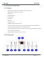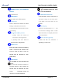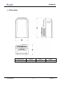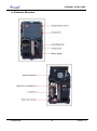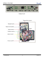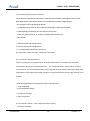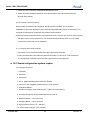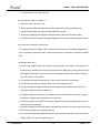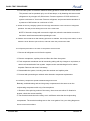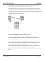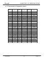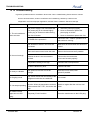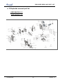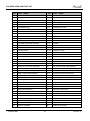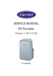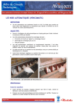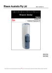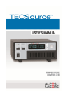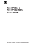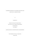
1
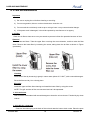
Portable MAF Series Models: AWPO-MAF009-C11 AWPO-MAF012-C11 REFRIGERANT REFRIGERANT R410A SM MAF 1-A.1 GB COOLONLY JAN, 2014 CONTENTS CONTENTS 1.1 Safety Precaution. .............................................................................................................................. 1 1.2 Warning ............................................................................................................................................... 1 2. Specification ......................................................................................................................................... 5 3. Function and control panel ................................................................................................................. 6 3.1 Function .............................................................................................................................................. 6 3.2 Control panel ...................................................................................................................................... 6 4 Dimension .............................................................................................................................................. 8 5 Refrigerant Cycle Diagram ................................................................................................................... 9 6 Wiring Diagram .................................................................................................................................... 10 7 Electronic function ...............................................................................................................................11 7.1 Terms and definitions .......................................................................................................................11 7.2 Electric Control working environment ............................................................................................11 7.3 Protection function ...........................................................................................................................11 7.4 Fan-only mode function requirement .............................................................................................11 7.5 Cooling mode function requirement ...............................................................................................11 7.6 Drying mode ..................................................................................................................................... 12 7.7 Heating mode (Optional) ................................................................................................................. 13 7.8 Heat pump mode (optional)............................................................................................................. 14 7.9 Sensor malfunction .......................................................................................................................... 15 8 Internal Structure ................................................................................................................................ 16 9 Care and maintenance ........................................................................................................................ 19 10 Basic test procedure ......................................................................................................................... 21 10.1 Defective compressor.................................................................................................................... 21 10.2 Sealed refrigeration system repairs ............................................................................................. 23 10.3 Fan motor ........................................................................................................................................ 26 10.4 Capacitor ......................................................................................................................................... 26 11 Characteristic of temperature sensor ............................................................................................. 28 12 Troubleshooting ................................................................................................................................ 29 13 Exploded view and part list .............................................................................................................. 30 PRECAUTION 1 Precaution 1.1 Safety Precaution. To prevent injury to the user or other people and property damage, the following instructions must be followed. Incorrect operation due to ignoring instruction will cause harm or damage. Before service unit, be sure to read this service manual at first. 1.2 Warning Installation Do not use a defective or underrated circuit breaker. Use this appliance on a dedicated circuit. There is risk of fire or electric shock. For electrical work, contact the dealer, seller, a qualified electrician, or an Authorized service center. Do not disassemble or repair the product, there is risk of fire or electric shock. Always ground the product. There is risk of fire or electric shock. Install the panel and the cover of control box securely. There is risk of fire of electric shock. Always install a dedicated circuit and breaker. Improper wiring or installation may cause fore or electric shock. Use the correctly rated breaker of fuse. There is risk of fire or electric shock. Do not modify or extend the power cable. There is risk of fire or electric shock. Do not install, remove, or reinstall the unit by yourself(customer). There is risk of fire, electric shock, explosion, or injury. Be caution when unpacking and installing the product. Sharp edges could cause injury, be especially careful of the case edges and the fins on the condenser and evaporator. For installation, always contact the dealer or an Authorized service center. There is risk of fire, electric shock, explosion, or injury. Do not install the product on a defective installation stand. Portable MAF 1 Version - 0 PRECAUTION It may cause injury, accident, or damage to the product. Be sure the installation area does not deteriorate with age. If the base collapses, the air conditioner could fall with it, causing property damage, product failure, and personal injury. Do not let the air conditioner run for a long time when the humidity is very high and a door or a window is left open. Moisture may condense and wet or damage furniture. Take care to ensure that power cable could not be pulled out or damaged during operation. There is risk of fire or electric shock. Do not place anything on the power cable. There is risk of fire or electric shock. Do not plug or unplug the power supply plug during operation. There is risk of fire or electric shock. Do not touch (operation) the product with wet hands. There is risk of fire or electric shock. Do not place a heater or other appliance near the power cable. There is risk of fire and electric shock. Do not allow water to run into electric parts. It may cause fire, failure of the product, or electric shock. Do not store or use flammable gas or combustible near the product. There is risk of fire or failure of product. Do not use the product in a tightly closed space for a long time. Oxygen deficiency could occur. When flammable gas leaks, turn off the gas and open a window for ventilation before turn the product on. Do not use the telephone or turn switches on or off. There is risk of explosion or fire. If strange sounds, or small or smoke comes from product. Turn the breaker off or disconnect the power supply cable. There is risk of electric shock or fire. Stop operation and close the window in storm or hurricane. If possible, remove the product from the window before the hurricane arrives. Portable MAF 2 Version - 0 PRECAUTION There is risk of property damage, failure of product, or electric shock. Do not open the inlet grill of the product during operation. (Do not touch the electrostatic filter, if the unit is so equipped.) There is risk of physical injury, electric shock, or product failure. When the product is soaked (flooded or submerged), contact an Authorized service center. There is risk of fire or electric shock. Be caution that water could not enter the product. There is risk of fire, electric shock, or product damage. Ventilate the product from time to time when operating it together with a stove, etc. There is risk of fire or electric shock. Turn the main power off when cleaning or maintaining the product. There is risk of electric shock. When the product is not be used for a long time, disconnect the power supply plug or turn off the breaker. There is risk of product damage or failure, or unintended operation. Take care to ensure that nobody could step on or fall onto the outdoor unit. This could result in personal injury and product damage. CAUTION Always check for gas (refrigerant) leakage after installation or repair of product. Low refrigerant levels may cause failure of product. Install the drain hose to ensure that water is drained away properly. A bad connection may cause water leakage. Keep level even when installing the product. To avoid vibration of water leakage Do not install the product where the noise or hot air from the outdoor unit could damage the neighborhoods. It may cause a problem for your neighbors. Use two or more people to lift and transport the product. Avoid personal injury. Do not install the product where it will be exposed to sea wind (salt spray) directly. It may cause corrosion on the product. Corrosion, particularly on the condenser and evaporator fins, could Portable MAF 3 Version - 0 PRECAUTION cause product malfunction or inefficient operation. Operational Do not expose the skin directly to cool air for long periods of time. (Do not sit in the draft). This could harm to your health. Do not use the product for special purposes, such as preserving foods, works of art, etc. It is a consumer air conditioner, not a precision refrigerant system There is risk of damage or loss of property. Do not block the inlet or outlet of air flow. It may cause product failure. Use a soft cloth to clean. Do not use harsh detergents, solvents, etc. There is risk of fire, electric shock, or damage to the plastic parts of the product. Do not touch the metal parts of the product when removing the air filter. They are very sharp. There is risk of personal injury. Do not step on pr put anything on the product. (outdoor units) There is risk of personal injury and failure of product. Always insert the filter securely. Clean the filter every two weeks or more often if necessary. A dirty filter reduces the efficiency of the air conditioner and could cause product malfunction or damage. Do not insert hands or other object through air inlet or outlet while the product is operated. There are sharp and moving parts that could cause personal injury. Do not drink the water drained from the product. It is not sanitary could cause serious health issues. Use a firm stool or ladder when cleaning or maintaining the product. Be careful and avoid personal injury. Replace the all batteries in the remote control with new ones of the same type. Do not mix old and new batteries or different types of batteries. There is risk of fire or explosion. Do not recharge or disassemble the batteries. Do not dispose of batteries in a fire. They may burn of explode. If the liquid from the batteries gets onto your skin or clothes, wash it well with clean water. Do not use the remote of the batteries have leaked. The chemical in batteries could cause burns or other health hazards Portable MAF 4 Version - 0 SPECIFICATION 2. Specification Model Characteristics Capacity (1) EER AWPO-MAF009-C11 AWPO-MAF012-C11 Units Cooling Cooling kW 2,6 3,5 W/W 2,6 2,6 A A V/Ph/Hz 220-240V/Single/50Hz 220-240V/Single/50Hz A 17 21 Cross flow fan x1 Cross flow fan x1 Energy efficiency class Power supply Circuit breaker rating INDOOR Fan type & quantity Fan speeds H/M/L RPM 780/690/650 780/690/650 Air flow (3) H/M/L m3/hr 370 370 Min-Max Pa 0 0 H/M/L dB(A) 64 65 H/M/L dB(A) 52/49/46 52/48/45 Moisture removal l/hr 1 1.2 Condensate drain tube I.D mm Capiliary Capiliary Rotary Rotary Cross flow fan x1 Cross flow fan x1 1020/680 1020/680 External static pressure Sound power level (4) OUTDOOR Side Sound pressure level (5) Refrigerant control Compressor type, model Fan type & quantity Fan speeds H/L RPM Air flow H/L m3/hr WxHxD mm 467x765x397 467x765x397 kg 30 33.5 mm 517x880x437 517x880x437 kg 34 37 units 4 levels 4 levels R410A R410A 0,43 0,54 Remote control Remote control Dimensions Weight Package dimensions WxHxD Packaged weight Stacking height Refrigerant type Refrigerant charge kg Operation control type Portable MAF 5 Version - 0 PRECAUTION 3. Function and control panel 3.1 Function ※ Operation mode: Cooling, Dry, Fan, Heating(optional) and Auto(optional) . ※ Optional function:Auto Auto swing, I-feel, ION. ※ Timer function. ※ Flexible installation kit. ※ No bucket design. ※ LED display. ※ Sleep mode. ※ Temperature sensor. ※ Self-diagnosis and auto-protection function. ※ Anti-freezing control in cooling or drying mode. Prevent the water being freezed on evaporator by sensing the evaporator pipe temperature in cooling or drying mode. ※ Auto-restart. When the power supply is interrupted and then restore, the air conditioners automatically restore the previous function setting. ※ Time Delay Safety. Restarting is for approx. 3 minutes. 3.2 Control panel Portable MAF 6 Version - 0 FUNCTION AND CONTROL PANEL Displayed when the “timer POWER button with OPERATION indicator off” is set and activated. Power switch on/off. SWING button(optional) SLEEP button Press this button to begin continuous up Used to initiate the SLEEP operation. and down swing of fan louver door. FAN button Press again to fix louver door into one Press to select four different fan speed settings: LOW,MED,HI and AUTO. position. LED Display An indicator light will illuminate for each Shows the set temperature in "℃" speed setting. the Auto-timer settings. While in DRY UP (+) and DOWN (-) button - and FAN modes, the display shows the (cooler) Press this button to decrease the set temperature. room temperature. I-Feel indication(optional) + (warmer) Press this button to Indicate that the air conditioner is increase the set temperature. operating in I FEEL mod MODE button Press this button to select the operating mode in sequence that advance from AUTO to COOL to DRY to FAN. An indicator light will illuminate for each mode setting. Timer button Used to initiate the AUTO ON start time and AUTO OFF stop time program, in conjuction with the (-)&(+) buttons. An indicator light will illuminate with each setting. Displayed when the “timer on” is set and activated. Portable MAF and 7 Version - 0 DIMENSION 4 Dimension Portable MAF Unit Dimension W(mm) H(mm) D(mm) Single-hole 467 765 397 8 Version - 0 REFRIGERANT CYCLE DIAGRAM 5 Refrigerant Cycle Diagram The figure below is a brief description of the important components and their function in what is called the refrigeration system. This will help to understand the refrigeration cycle and the flow of the refrigerant in the cooling cycle. LIQUID SIDE CAPILIARY TUBE CONDENSER EVAPORATOR GAS SIDE Portable MAF COMPRESSOR 9 Version - 0 ELECTRONIC FUNCTION 6 Wiring Diagram Portable MAF 10 Version - 0 ELECTRONIC FUNCTION 7 Electronic function 7.1 Terms and definitions TC: Temperature of evaporator (T2). TA: Temperature of indoor ambient (T1). TS: The set temperature. TE: Temperature of condenser (T3) 7.2 Electric Control working environment Input voltage: 97~127V for 60Hz models; 7.3 Protection function 7.3.1 The compressor functions protection with a delay of three minutes. 7.3.2 Sensor protection at open or short circuit. 7.3.3 Evaporator anti-icing protection at cooling mode. 7.4 Fan-only mode function requirement 7.4.1. The compressor and outdoor fan are OFF at Fan-only mode (except P1 protection). 7.4.2. The speed of indoor fan can be optionally chosen as High/Mid/Low. 7.4.3. The TS can’t be controlled, and the LED displays as T1. 7.4.4. The ION/TIMER functions are valid at the fan-only mode. 7.5 Cooling mode function requirement 7.5.1. The speed of indoor fan can be optionally selected as High/Mid/Low. 7.5.2. The outdoor fan will be turned on as soon as the unit being on cooling mode. The operation of outdoor fan is according to the compare of TA and TS when the water level is below to switch 1. If not, the outdoor fan doesn’t work. 7.5.3. The compressor operates as below: Portable MAF 11 Version - 0 ELECTRONIC FUNCTION Operation conditon (TA-Ts)℃ Compressor on +1 0 Compressor off 7.5.2.1 If TA﹥TS+1℃, the outdoor fan operates. After 15 seconds, the compressor operates. 7.5.2.2 The compressor is on, if TA≤TS, this compressor will stop. If the outdoor fan operates for 3 minutes at least, it will stop after delaying for 5 seconds. 7.5.3. When the unit is off, the compressor stops at first, and the indoor/outdoor fan will stop after delaying for 5seconds. (If it operates at heating mode, the outdoor fan will be off delaying for 30 seconds). 7.5.4. Power management (for power management models) Entering into the only-cooling mode, indoor fan motor operates immediately and keeps moving for 30 minutes at lease. Compressor operates, and indoor fan motor keeps moving; Compressor stops operation, indoor fan motor shuts off after a delay of 30 minutes. 7.5.5. The ION/TIMER functions are valid at the cooling mode. 7.6 Drying mode 7.6.1. The unit operates at drying mode. If TA>13℃, outdoor fan turns on, and then the compressor operates after 15 seconds later. Portable MAF 12 Version - 0 ELECTRONIC FUNCTION Operation conditon Compressor on TA ℃ 15 13 Compressor off 7.6.1.1 When TA<13℃, the compressor stops working. And the outdoor fan will stop delaying for 5 seconds until it operates for 3minutest. 7.6.1.2 When TA≥15℃, the outdoor fan operates, and the compressor will restart to operate after 15seconds. 7.6.2. The speed can’t be controlled at drying mode, and the indoor fan motor operates at low speed. 7.6.3 Power management (for power management models) Entering into drying mode, indoor fan motor operates immediately and keeps moving for 30 minutes at lease. Compressor operates, and indoor fan motor keeps moving; Compressor stops operation, indoor fan motor shuts off after a delay of 30 minutes. 7.6.4. The ION/TIMER functions are valid at the drying mode. 7.7 Heating mode (Optional) 7.7.1. The speed of indoor fan can be optionally chosen as High/Mid/Low. The compressor and outdoor fan keep on stop (except P1 protection) 7.7.2. At heating mode, the heater will operate according to the difference between TA and TS. Electric heater operates as below Portable MAF 13 Version - 0 ELECTRONIC FUNCTION Operation conditon (TA-Ts)℃ Heater off +1 0 Heater on 7.7.2.1. When TA﹤TS, the indoor fan operates firstly, and then the heater operates after 4 seconds. 7.7.2.2. If TA﹥TS+1℃, the heater stops. Then the heater turns off after 10 seconds. When the unit is off at the heating mode, the indoor fan motor stops delaying for 10 seconds 7.7.3. The ION/TIMER functions are valid at the heating mode. 7.8 Heat pump mode (optional) 7.8.1. When TA≤TS+5℃, compressor operates; When TA﹥TS+6℃, compressor stops. When TA ﹤ 5 ℃ , heat pump mode is invalid, and water pump/indoor motor/outdoor motor/compressor/ shaded pole motor stop; When TA≥6℃, heat pump mode resumes to be valid. 7.8.2. At non-defrosting situation, shaded pole motor always stops ; Compressor operates; Outdoor motor is on at high speed. Then outdoor motor stops at a delay of 30s when compressor is off. When unit is change for other mode(non-heating mode), Four-way valve shuts off at a delay of 2 minutes than compressor. 7.8.3. Condition of entering into defrosting mode: when the operation time of T3(T3≤2℃ continuous) is up to 2040minutes. Defrosting motion: 1) Compressor operates; Four-way valve and indoor /outdoor motors shut off. 2) When TA﹥40℃ or time is more than 7 minutes, outdoor motor is on until defrosting is over. Portable MAF 14 Version - 0 ELECTRONIC FUNCTION 7.8.4 When meeting one of conditions as below, unit finishes defrosting motion. 1) The time of defrosting is up to 10 minutes. 2) TE≥50℃ 7.8.5 Finishing defrosting motion: Outdoor motor is on, and compressor is off. 7.8.6 Compressor delay protection is invalid when unit entering into or finishing defrosting motion. 7.8.7 At heat pump mode, compressor/indoor motor/outdoor motor shut off immediately when water full protection is on. 7.8.8 The ION/TIMER functions are valid at the heat pump mode. 7.8.9 Non-defrosting motion (for power management models): The unit enters into the heat pump mode for the first time, four-way valve opens. When compressor shuts off, the four-way valve closes at a delay of 10 minutes. Compressor operates, and the four-way valve keeps opening. When unit is on malfunction, four-way valve closes; Four-way valve resumes with the compressor operating 7.9 Sensor malfunction LED display Stand for E2 T2 sensor malfunction E1 T1 sensor malfunction E4 Communication malfunction for display board and PCB E3 T3 sensor malfunction P1 Water full protection Malfunction display: When the malfunction happened at the same time, the priority is E4> E3> E2> E1>P1 Portable MAF 15 Version - 0 INTERNAL STRUCTURE 8 Internal Structure Portable MAF 16 Version - 0 INTERNAL STRUCTURE Portable MAF 17 Version - 0 INTERNAL STRUCTURE Portable MAF 18 Version - 0 CARE AND MAINTENENCE 9 Care and maintenance Important 1) Be sure to unplug the unit before cleaning or servicing. 2) Do not use gasoline, thinner or other chemicals to clean the unit. 3) Do not wash the unit directly under a tap or using a hose. It may cause electrical danger. 4) If the power cord is damaged, it should be repaired by manufacture or its agency. 1. Air filter Clean the air filter at least once every two weeks to prevent inferior fan operation because of dust. Removal This unit has two filters. Take the upper filter out along the arrow direction, and then take the filter down. Remove the lower filter by loosening the screw, taking down the air filter as shown in Figure (see below). Cleaning Wash the air filter by immersing it gently in warm water (about 40℃/104℉) with a neutral detergent. Rinse the filter and dry it in a shady place. Mounting Install the upper air filter after cleaning and install the lower filter by using the screw. NOTE: The grill and the air filer are connected and can’t be separated. 2. Unit enclosure Use a lint-free cloth soaked with neutral detergent to clean the unit enclosure. Finished by dry clean clothes. 3. Unit idle for a long time ※Remove the rubber plug at the back of the unit and attach a hose to drain outlet. Place the open Portable MAF 19 Version - 0 CARE AND MAINTENANCE end of the hose directly over the drain area in your basement floor (See below Figure). ※Remove the plug from the bottom drain outlet, all the water in the bottom tray would drain out (See below Figure) ※Keep the appliance running on FAN mode for half a day in a warm room to dry the appliance inside and prevent mold forming. ※Stop the appliance and unplug it, wrapped the cord and bundle it with the tape. Remove the batteries from the remote controller. ※Clean the air filter and reinstall it. ※Disconnect the exhaust hose, keep it safety, and cover the window(wall) hole with the adaptor cap Portable MAF 20 Version - 0 BASIC TEST PROCEDURE 10 Basic test procedure 10.1 Defective compressor Compressors are single phase, depending on the model unit. All compressor motors are permanent split capacitor type using only a running capacitor across the start and run terminal. All compressors are internally spring mounted and externally mounted on rubber isolators. 10.1.1 Compressor wiring test Remove compressor terminal box cover and disconnect wires from terminals. Using an ohmmeter, check continuity across the following: Terminal "C" and "S" - no continuity - Open winding - replace compressor. Terminal "C" and "R" - no continuity - Open winding - replace compressor. Terminal "R" and "S" - no continuity - Open winding - replace compressor. 10.1.2 Ground test Use an ohmmeter to set on its highest scale. Touch one lead to the compressor body (clean point of contact as a good connection is a must) and the other probe in turn to each compressor terminal (see Figure 2.) If a reading is obtained, the compressor is grounded and must be replaced. Portable MAF 21 Version - 0 BASIC TEST PROCEDURE 10.1.3 Checking the compressor efficiency The reason for compressor inefficiency is normally due to broken or damaged suction and/or discharge valves, reducing the ability of the compressor to pump refrigerant gas. This condition can be checked as follows: 1. Install a piercing valve on the suction and discharge or liquid process tube. 2. Attach gauges to the high and low sides of the system. 3. Start the system and run a “cooling or heating performance test.” If test shows: A. Below normal high side pressure. B. Above normal low side pressure. C. Low temperature difference across coil. The compressor valves are faulty - replace the compressor 10.1.4 Terminal overload (external) Some compressors are equipped with an external overload which is located in the compressor terminal box adjacent to the compressor body. The overload is wired in series with the common motor terminal. The overload senses both major amperage and compressor temperature. High motor temperature or amperage heats the disc causing it to open and break the circuit to the common motor terminal. Heat generated within the compressor shell is usually due to: 1. High amperage. 2. Low refrigerant charge. 3. Frequent recycling. 4. Dirty condenser. 10.1.5 Terminal overload – Test (compressor external type) 1. Remove overload. Portable MAF 22 Version - 0 BASIC TEST PROCEDURE 2. Allow time for overload to reset before attempting to test. 3. Apply ohmmeter probes to terminals on overload wires. There should be continuity through the overload. 10.1.6 Terminal overload (internal) Some model compressors are equipped with an internal overload. The overload is embedded in the motor windings to sense the winding temperature and/or current draw. The overload is connected in series with the common motor terminal. Should the internal temperature and/or current draw become excessive; the contacts in the overload will open, turning off the compressor? The overload will automatically reset, but may require several hours before the heat is dissipated. 10.1.7 Checking the internal overload 1. No power to unit, remove the leads from the compressor terminals. 2. Using an ohmmeter, test continuity between terminals C-S and C-R. If not continuous, the compressor overload is open and the compressor must be replaced. 10.2 Sealed refrigeration system repairs 10.2.1 Equipment require 1. Voltmeter 2. Ammeter 3. Ohmmeter 4. E.P.A. Approved Refrigerant Recovery System. 5. Vacuum Pump (capable of 200 microns or less vacuum.) 6. Acetylene Welder 7. Electronic Halogen Leak Detector (G.E. Type H-6 or equivalent.) 8. Accurate refrigerant charge measuring device such as: a. Balance Scales - 1/2 oz. accuracy b. Charging Board - 1/2 oz. accuracy 9. High Pressure Gauge - (0 - 400 lbs.) 10. Low Pressure Gauge - (30 - 150 lbs.) Portable MAF 23 Version - 0 BASIC TEST PROCEDURE 11. Vacuum Gauge - (0 - 1000 microns) 10.2.2 Equipment must be capable of: 1. Recovery CFC's as low as 5%. 2. Evacuation from both the high side and low side of the system simultaneously. 3. Introducing refrigerant charge into high side of the system. 4. Accurately weighing the refrigerant charge actually introduced into the system. 5. Facilities for flowing nitrogen through refrigeration tubing during all brazing processes. 10.2.3 Hermetic compressor replacement. The following procedure applies when replacing components in the sealed refrigeration circuit or repairing refrigerant leaks. (Include Compressor, condenser, evaporator, capillary tube, refrigerant leaks, etc.) 1. Recover the refrigerant from the system at the process tube located on the high side of the system by installing a line tap on the process tube. Apply gauge from process tube to EPA approved gauges from process tube to EPA approved recovery system. Recover CFCs in system to at least 5%. 2. Cut the process tube below pinch off on the suction side of the compressor. 3. Connect the line from the nitrogen tank to the suction process tube. 4. Drift dry nitrogen through the system and unsolder the more distant connection first. (Filter drier, high side process tube, etc.) 5. Replace inoperative component, and always install a new filter drier. Drift dry nitrogen through the system when making these connections. 6. Pressurize system to 30 PSIG with proper refrigerant and boost refrigerant pressure to 150 PSIG with dry nitrogen. 7. Leak test complete system with electric halogen leak detector, correcting any leaks found. 8. Reduce the system to zero gauge pressure. 9. Connect vacuum pump to high side and low side of system with deep vacuum hoses or copper tubing. (Do not use regular hoses.) Portable MAF 24 Version - 0 BASIC TEST PROCEDURE 10. Evacuate system to maximum absolute holding pressure of 200 microns or less. NOTE: This process can be speeded up by use of heat lamps, or by breaking the vacuum with refrigerant or dry nitrogen at 5,000 microns. Pressure system to 5 PSIG and leave in system a minimum of 10 minutes. Recover refrigerant, and proceed with evacuation of a pressure of 200 microns or a minimum of 10%. 11. Break vacuum by charging system from the high side with the correct amount of refrigerant specified. This will prevent boiling the oil out of the crankcase. NOTE: If the entire charge will not enter the high side, allow the remainder to enter the low side in small increments while operating the unit. 12. Restart unit several times after allowing pressures to stabilize. Pinch off process tubes, cut and solder the ends. Remove pinch off tool, and leak check the process tube ends 10.2.4 Special procedure in the case of compressor motor burnout 1. Recover all refrigerant and oil from the system. 2. Remove compressor, capillary tube and filter drier from the system. 3. Flush evaporator condenser and all connecting tubing with dry nitrogen or equivalent, to remove all contamination from system. Inspect suction and discharge line for carbon deposits. Remove and clean if necessary. 4. Reassemble the system, including new drier strainer and capillary tube. 5. Proceed with processing as outlined under hermetic component replacement. 10.2.5 Rotary compressor special troubleshooting and service Basically, troubleshooting and servicing rotary compressors is the same as on the reciprocating compressor with only a few exceptions. 1. Because of the spinning motion of the rotary, the mounts are critical. If vibration is present, check the mounts carefully. 2. The electrical terminals on the rotary are in a different order than the reciprocating compressors. The terminal markings are on the cover gasket. Use your wiring diagram to insure correct connections. Portable MAF 25 Version - 0 BASIC TEST PROCEDURE 10.2.6 Refrigerant charge 1. The refrigerant charge is extremely critical. It must be measured charge carefully - as exact as possible to the nameplate charge. 2. The correct method for charging the rotary is to introduce liquid refrigerant into the high side of the system with the unit off. Then start compressor and enter the balance of the charge, gas only, into the low side. The introduction of liquid into the low side, without the use of a capillary tube, will cause damage to the discharge valve of the rotary compressor. NOTE: All inoperative compressors returned to Friedrich must have all lines properly plugged with the plugs from the replacement compressor. 10.3 Fan motor A single phase permanent split capacitor motor is used to drive the evaporator blower and condenser fan. A self-resetting overload is located inside the motor to protect against high temperature and high amperage conditions. 10.3.1 Fan motor test 1. Determine that capacitor is serviceable. 2. Disconnect fan motor wires from fan speed switch or system switch. 3. Apply "live" test cord probes on black wire and common terminal of capacitor. Motor should run at high speed. 4. Apply "live" test cord probes on red wire and common terminal of capacitor. Motor should run at low speed. 5. Apply "live" test cord probes on each of the remaining wires from the speed switch or system switch to test intermediate speeds. 10.4 Capacitor A run capacitor is wired across the auxiliary and main winding of a single phase permanent Portable MAF 26 Version - 0 BASIC TEST PROCEDURE split capacitor motor such as the compressor and fan motor. A single capacitor can be used for each motor or a dual rated capacitor can be used for both. The capacitor's primary function is to reduce the line current while greatly improving the torque characteristics of a motor. The capacitor also reduces the line current to the motor by improving the power factor of the load. Run capacitor hook-up line side of the capacitor is marked with a red dot and is wired to the line side of the circuit Capacitor test: 1. Remove capacitor from unit. 2. Check for visual damage such as bulges, cracks, or leaks 3. For dual rated, apply an ohmmeter lead to common (C) terminal and the other probe to the compressor (HERM) terminal. A satisfactory capacitor will cause a deflection on the pointer, and then gradually move back to infinity. 4. Reverse the leads of the probe and momentarily touch the capacitor terminals. The deflection of the pointer should be two times that of the first check if the capacitor is good. 5. Repeat steps 3 and 4 to check fan motor capacitor. NOTE: A shorted capacitor will indicate a low resistance and the pointer will move to the "0" end of the scale and remain there as long as the probes are connected. An open capacitor will show no movement of the pointer when placed across the terminals of the capacitor Portable MAF 27 Version - 0 CHARACTERISTIC OF TEMPERATURE SENSOR 11 Characteristic of temperature sensor Temp.℃ Resistance KΩ Temp.℃ Resistance KΩ Temp.℃ Resistance KΩ -10 62.2756 17 14.6181 44 4.3874 -9 58.7079 18 13.918 45 4.2126 -8 56.3694 19 13.2631 46 4.0459 -7 52.2438 20 12.6431 47 3.8867 -6 49.3161 21 12.0561 48 3.7348 -5 46.5725 22 11.5 49 3.5896 -4 44 23 10.9731 50 3.451 -3 41.5878 24 10.4736 51 3.3185 -2 39.8239 25 10 52 3.1918 -1 37.1988 26 9.5507 53 3.0707 0 35.2024 27 9.1245 54 2.959 1 33.3269 28 8.7198 55 2.8442 2 31.5635 29 8.3357 56 2.7382 3 29.9058 30 7.9708 57 2.6368 4 28.3459 31 7.6241 58 2.5397 5 26.8778 32 7.2946 59 2.4468 6 25.4954 33 6.9814 60 2.3577 7 24.1932 34 6.6835 61 2.2725 8 22.5662 35 6.4002 62 2.1907 9 21.8094 36 6.1306 63 2.1124 10 20.7184 37 5.8736 64 2.0373 11 19.6891 38 5.6296 65 1.9653 12 18.7177 39 5.3969 66 1.8963 13 17.8005 40 5.1752 67 1.83 14 16.9341 41 4.9639 68 1.7665 15 16.1156 42 4.7625 69 1.7055 16 15.3418 43 4.5705 70 1.6469 Portable MAF 28 Version - 0 TROUBLESHOOTING 12 Troubleshooting In general, possible trouble is classified in three kinds. One is called Starting Failure which is caused from an electrical defect, another is ineffective Air Conditioning caused by a defect in the refrigeration circuit and improper application, and the other is called the Structure Damage. TROUBLES POSSIBLE CAUSES SUGGEST REMEDIES 1. The air conditioner does not start. The power supply is not connected well. The power plug is not inserted tightly. Power plug or socket is malfunctioning. The fuse is broken. 1. Insert the power plug tightly. 2. Have an electrician replace the power plug or socket. 3. Have an electrician replace the fuse. Is TIMER ON is operation? Cancel the “SET TIMER” operation or to wait until auto running. The windows or doors in the room are not closed. Make sure all the windows and doors are closed. There are heat sources inside the room. Remove the heat sources if possible. Exhaust air duct is not connected or blocked. Connect the duct and make sure it can function properly. Temperature setting is too high. Decrease the set temperature. Air filter is blocked by dust. Clean the air filter. 3. Noisy or vibration The ground is not level or not flat enough. Place the unit on a flat, level ground if possible. 4.Gurgling sound The sound comes from the flowing of the refrigerant inside the air conditioner. It is normal. 5. Unit stops operating The automatic over heat protection function. When the temperature at the air outlet exceed 158℉/70℃, the device will stop. Switch on again after the unit has cool down. 6. RESET Button pops out on LCDI plug. Temporary Fault Condition Press the reset button on the LCDI plug. 2. Not cool enough Portable MAF 29 Version - 0 EXPLODED BIEW AND PART LIST 13 Exploded view and part list AWPO-MAF009-C11 AWPO-MAF012-C11 Portable MAF 30 Version - 0 EXPODED VIEW AND PART LIST Part list: No. Part Name 1 Front panel assembly 22 Cover of drain connector 1.1 Front panel 23 Drain pipe 1.2 Signal receiving board assembly 24 Drain stopper 1.3 Adorn board 24 Drain stopper 1.4 Upper panel 27 Chassis assembly 1.5 Horizontal louver 27.2 Shaded pole motor 1.6 Bracket 27.5 Water wheel 1.7 Gear wheel 27.6 Water level sensor 1.7 Gear wheel 27.7 Bracket of water level sensor 1.8 Louver motor 27.8 Micro switch 1.9 Mid panel 27.9 Bracket of Micro switch 1.10 Display box assembly 27.10 Dobber case 2 Air outlet volute shell assembly 27.11 Dobber 2.1 Asynchronous motor 27.12 Universal wheel 2.2 Air outlet volute shell 27.13 Chassis 2.3 Centrifugal fan 27.16 Waterproof foam 2.4 Cover of Air outlet volute shell 27.17 Top cover of Shaded pole motor 2.5 Air outlet grille 27.18 Bottom cover of Shaded pole motor 2.6 Fasten board of Capacitor 28 Compressor 2.7 Capacitor of fan motor 29 Supporting bar 2.8 Capacitor box 30 Pipe temperature sensor assembly 3 Dobber 31 Indoor temperature sensor assembly 5 Electronic control box assembly 32 Air exhaust volute shell assembly 5.1 Electronic control box 32.1 Asynchronous motor 5.2 Power module assembly 32.2 Cover of air exhause volute shell 5.3 Main control board assembly 32.3 Connector of air exchaust duct 6 Cover of electronic control box 32.4 Middle partition board 7 Suction pipe assembly 32.5 Centrifugal fan 8 Discharge pipe assembly 32.6 Power cord 10 Capillary assembly 33 Capacitor box 11 Evaporator coil assembly 34 Capacitor of compressor 12 Condenser assembly 35 Fasten board of Capacitor 13 Rear panel assembly 36 Capacitor of fan motor 14 Connector of air exchaust duct 37 Capacitor box 15 Flexible air exhaust hose 39 Outdoor air inlet grille assembly 16 Air exhaust passage 39.1 Outdoor air inlet grille 17 Air exhaust passage 39.2 filter 18 Window sealing board I 40 Connector, 19 Window sealing board II 41 Top filter 20 Remote controller 42 Indoor air inlet grille Portable MAF No. 31 Part Name air exchaust duct Version - 0 EXPLODED BIEW AND PART LIST SERVICE MANUAL Portable MAF Series Portable MAF 32 Version - 0