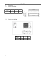
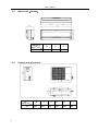
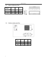
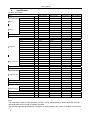
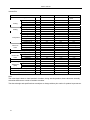
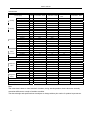
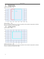
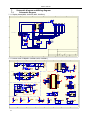
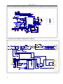
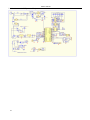
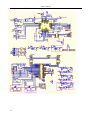
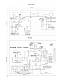
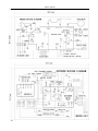
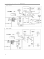
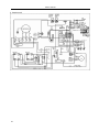
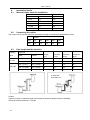
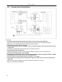
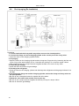
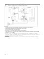
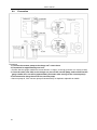
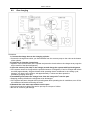
1
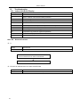
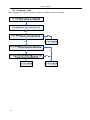
Content MSC-18HRIN1; MSH-18HRIN1(AAC-18ISCH) MSE-09HRIN2; MSE-12HRIN2 MSG-07CRIN2; MSG-09HRIN2 MSG-12HRIN2; MSG-09HRI ;MSG-12HRI MSG-21HRI ; MSG-24HRI 1 Content Content 1. Precaution .......................................................................................................................... 1 1.1 1.2 2. 3. Function.............................................................................................................................. 3 Dimension........................................................................................................................... 5 3.1 3.2 3.3 3.4 3.5 3.6 3.7 3.8 4. 5. 6. Indoor unit(Alfa) ............................................................................................................................ 5 Outdoor unit(Alfa).......................................................................................................................... 5 Indoor unit(Corona)....................................................................................................................... 6 Outdoor unit(Corona) .................................................................................................................... 6 Indoor unit(Inverter Eco) .................................................................................................................... 7 Outdoor unit(Inverter Eco) ................................................................................................................. 7 Indoor unit(Inverter Star).................................................................................................................... 8 Outdoor unit(Inverter Star) ................................................................................................................. 8 Specification....................................................................................................................... 9 Refrigerant cycle diagram ............................................................................................... 12 Operation limits................................................................................................................ 13 6.1 6.2 7. Cooling operation............................................................................................................................. 13 Heating operation ............................................................................................................................ 13 Schematic diagram and Wiring diagram........................................................................ 14 7.1. 7.2. 8. Schematic diagram .......................................................................................................................... 14 Wiring diagram ................................................................................................................................ 18 Installation details ............................................................................................................ 23 8.1 8.2 8.3 8.4 8.5 8.6 8.7 8.8 8.9 9. Wrench torque sheet for installation ................................................................................................ 23 Connecting the cables ..................................................................................................................... 23 Pipe length and the elevation .......................................................................................................... 23 Air purging of the piping and indoor unit .......................................................................................... 24 Pumping down (Re-installation) ....................................................................................................... 25 Re-air purging (Re-installation) ........................................................................................................ 26 Balance refrigerant of the 2-way, 3-way valves................................................................................ 27 Evacuation....................................................................................................................................... 28 Gas charging ................................................................................................................................... 29 Pressure table .................................................................................................................. 30 9.1 9.2 10. 10.1 10.2 10.3 10.4 10.5 10.6 2 Safety Precaution .............................................................................................................................. 1 Warning ............................................................................................................................................. 1 MSH-18HRIN1................................................................................................................................. 30 MSC-18HRIN1................................................................................................................................. 30 Capacity table................................................................................................................... 31 MSH-18HRIN1................................................................................................................................. 31 MSC-18HRIN1................................................................................................................................. 32 MSG-09HRI ..................................................................................................................................... 33 MSG-12HRI ..................................................................................................................................... 33 MSG-21HRI ..................................................................................................................................... 34 MSG-24HRI ..................................................................................................................................... 34 Content 11. Electronic function........................................................................................................... 35 11.1. 11.2. 11.3. 11.4. 11.5. 11.6. 11.7. 11.8. 11.9. 11.10. 11.11. 11.12. 11.13. 11.14. 11.15. 12. 13. 13.1 13.2 13.3 13.4 13.5 13.6 13.7 13.8 14 3 Display board................................................................................................................................... 35 Protection ........................................................................................................................................ 35 Fan-only mode................................................................................................................................. 35 Cooling mode .................................................................................................................................. 35 Dehumidifying mode ........................................................................................................................ 36 Heating mode .................................................................................................................................. 36 Defrosting operation (Available for heating only). ............................................................................ 38 Outdoor low temperature protection (optional) ................................................................................ 38 Automatic operation mode............................................................................................................... 38 Manual switch .................................................................................................................................. 39 Timer Function................................................................................................................................. 39 Sleep mode ..................................................................................................................................... 39 Auto restart function......................................................................................................................... 39 Turbo function.................................................................................................................................. 39 Plasma............................................................................................................................................. 39 Model and Parameters..................................................................................................... 40 Troubleshooting ............................................................................................................... 42 Indoor Unit Error Display ................................................................................................................. 42 Diagnostic chart ............................................................................................................................... 47 Resetting phenomenon often occurs during operation .................................................................... 48 Operation lamp flashes and Timer lamp off ..................................................................................... 48 Operation lamp flashes and Timer lamp on ..................................................................................... 48 Operation lamp off and Timer lamp flashes ..................................................................................... 49 Operation lamp on and Timer lamp flashes ..................................................................................... 49 Operation lamp flashes, Timer lamp flashes.................................................................................... 49 Characteristic of temperature sensor ............................................................................ 50 Service manual 1. 1.1 Precaution Safety Precaution To prevent injury to the user or other people and property damage, the following instructions must be followed. Incorrect operation due to ignoring instruction will cause harm or damage. Before service unit, be sure to read this service manual at first. 1.2 Warning ¾ Installation Do not use a defective or underrated circuit breaker. Use this appliance on a dedicated circuit. There is risk of fire or electric shock. For electrical work, contact the dealer, seller, a qualified electrician, or an Authorized service center. Do not disassemble or repair the product, there is risk of fire or electric shock. Always ground the product. There is risk of fire or electric shock. Install the panel and the cover of control box securely. There is risk of fire of electric shock. Always install a dedicated circuit and breaker. Improper wiring or installation may cause fore or electric shock. Use the correctly rated breaker of fuse. There is risk of fire or electric shock. Do not modify or extend the power cable. There is risk of fire or electric shock. Do not install, remove, or reinstall the unit by yourself (customer). There is risk of fire, electric shock, explosion, or injury. Be caution when unpacking and installing the product. Sharp edges could cause injury, be especially careful of the case edges and the fins on the condenser and evaporator. For installation, always contact the dealer or an Authorized service center. There is risk of fire, electric shock, explosion, or injury. Do not install the product on a defective installation stand. It may cause injury, accident, or damage to the product. Be sure the installation area does not deteriorate with age. If the base collapses, the air conditioner could fall with it, causing property damage, product failure, and personal injury. Do not let the air conditioner run for a long time when the humidity is very high and a door or a windows is left open. Moisture may condense and wet or damage furniture. Take care to ensure that power cable could not be pulled out or damaged during operation. There is risk of fire or electric shock. Do not place anything on the power cable. 1 There is risk of fire or electric shock. Do not plug or unplug the power supply plug during operation. There is risk of fire or electric shock. Do not touch (operation) the product with wet hands. There is risk of fire or electric shock. Do not place a heater or other appliance near the power cable. There is risk of fire and electric shock. Do not allow water to run into electric parts. It may cause fire, failure of the product, or electric shock. Do not store or use flammable gas or combustible near the product. There is risk of fire or failure of product. Do not use the product in a tightly closed space for a long time. Oxygen deficiency could occur. When flammable gas leaks, turn off the gas and open a window for ventilation before turn the product on. Do not use the telephone or turn switches on or off. There is risk of explosion or fire. If strange sounds, or small or smoke comes from product. Turn the breaker off or disconnect the power supply cable. There is risk of electric shock or fire. Stop operation and close the window in storm or hurricane. If possible, remove the product from the window before the hurricane arrives. There is risk of property damage, failure of product, or electric shock. Do not open the inlet grill of the product during operation. (Do not touch the electrostatic filter, if the unit is so equipped.) There is risk of physical injury, electric shock, or product failure. When the product is soaked (flooded or submerged), contact an Authorized service center. There is risk of fire or electric shock. Be caution that water could not enter the product. There is risk of fire, electric shock, or product damage. Ventilate the product from time to time when operating it together with a stove, etc. There is risk of fire or electric shock. Turn the main power off when cleaning or maintaining the product. Service manual There is risk of electric shock. When the product is not be used for a long time, disconnect the power supply plug or turn off the breaker. There is risk of product damage or failure, or unintended operation. Take care to ensure that nobody could step on or fall onto the outdoor unit. This could result in personal injury and product damage. ¾ CAUTION Always check for gas (refrigerant) leakage after installation or repair of product. Low refrigerant levels may cause failure of product. Install the drain hose to ensure that water is drained away properly. A bad connection may cause water leakage. Keep level even when installing the product. To avoid vibration of water leakage. Do not install the product where the noise or hot air from the outdoor unit could damage the neighborhoods. It may cause a problem for your neighbors. Use two or more people to lift and transport the product. Avoid personal injury. Do not install the product where it will be exposed to sea wind (salt spray) directly. It may cause corrosion on the product. Corrosion, particularly on the condenser and evaporator fins, could cause product malfunction or inefficient operation. ¾ Operational Do not expose the skin directly to cool air for long periods of time. (Do not sit in the draft). This could harm to your health. Do not use the product for special purposes, such as preserving foods, works of art, etc. It is a 2 consumer air conditioner, not a precision refrigerant system. There is risk of damage or loss of property. Do not block the inlet or outlet of air flow. It may cause product failure. Use a soft cloth to clean. Do not use harsh detergents, solvents, etc. There is risk of fire, electric shock, or damage to the plastic parts of the product. Do not touch the metal parts of the product when removing the air filter. They are very sharp. There is risk of personal injury. Do not step on pr put anything on the product. (outdoor units) There is risk of personal injury and failure of product. Always insert the filter securely. Clean the filter every two weeks or more often if necessary. A dirty filter reduces the efficiency of the air conditioner and could cause product malfunction or damage. Do not insert hands or other object through air inlet or outlet while the product is operated. There are sharp and moving parts that could cause personal injury. Do not drink the water drained from the product. It is not sanitary could cause serious health issues. Use a firm stool or ladder when cleaning or maintaining the product. Be careful and avoid personal injury. Replace the all batteries in the remote control with new ones of the same type. Do not mix old and mew batteries or different types of batteries. There is risk of fire or explosion. Do not recharge or disassemble the batteries. Do not dispose of batteries in a fire. They may burn of explode. If the liquid from the batteries gets onto your skin or clothes, wash it well with clean water. Do not use the remote of the batteries have leaked. The chemical in batteries could cause burns or other health hazards. Service manual 2. Function Indoor unit Operation ON/OFF by remote controller Sensing by room temperature Room temperature sensor. Pipe temperature sensor. Room temperature control Maintain the room temperature in accordance with the setting temperature. Anti-freezing control in cooling Prevent the water being freezed on evaporator by sensing the evaporator pipe temperature in cooling mode Work voltage (160v-253v) High efficiency (30%) Time Delay Safety control Restarting is for approx. 3 minutes.. Indoor fan speed control Tele Remote control (Optional) Self-diag. function Turbo wind, high, med, low, breeze. Anti-cold function Two-direction air vane The unit will decide the louver direction according to operation mode. Sleep mode auto control The fan is turn to low speed (cooling/heating). The unit will be turn off at the seventh hour. Independent dehumidification The function is usually used in rainy days in springtime or damp areas. Air flow Direction control The louver can be set at the desired position or swing up and down automatically Auto mode The mode can be change by the room temperature. Prevent the cold wind at the beginning of unit start. Plasma (Optional) The function will be operated in any operation mode. Auto defrost Auto-restart function When the power supply is interrupted and then restore, the air conditioners automatically restore the previous function setting. Flexible wiring connection DSP High-speed Chip Temp. Compensation Driving heating at -15℃ 3 Service manual Outdoor unit Power relay control The unit has 3 mins delay between continuously ON/OFF operations. Low noise air flow system Bird tail propeller fan makes the outdoor unit run more quietly. Hydrophilic aluminum fin The hydrophilic fin can improve the heating efficiency at operation mode. 4 way valve control It is only operated in the heating operation mode except defrosting operation. Anti-rust cabinet Made from electrolytic zinc steel sheet and anti-rust coated components. Valve protection cover It protects the valves and prevents water from dripping. Discharge pipe temperature protect 4 Service manual 3. 3.1 Dimension Indoor unit(Alfa) Dimension Mode W H D 12K 815 280 215 3.2 Outdoor unit(Alfa) Dimension Mode 12K 5 W H D 760 590 285 Service manual 3.3 Indoor unit(Corona) Dimension Mode 18K 3.4 H D 920 292 225 Outdoor unit(Corona) Dimension Mode 18K 6 W W 845 H D 695 335 L1 L2 L3 560 360 560 Service manual 3.5 Indoor unit(Inverter Eco) Dimension Mode W H D 7K 750 250 188 9K 750 250 188 12K 815 280 195 3.6 Outdoor unit(Inverter Eco) Dimension Mode 7 W H D 7K 780 540 250 9K 780 540 250 12K 780 540 250 Service manual 3.7 Indoor unit(Inverter Star) Dimension Mode W H D 7K 750 250 205 9K 750 250 205 12K 815 280 215 3.8 Outdoor unit(Inverter Star) Dimension Mode 8 W H D 7K 760 590 285 9K 760 590 285 12K 760 590 285 Service manual 4. Specification Ac Alfa,Ac Corona Model MSC-18HRIN1 MSE-09HRIN2 MSE-12HRIN2 Ph-V-Hz 1, 220-240V~, 50Hz MSH-18HRIN1 1, 220-240V~,50Hz 1, 220-240V~, 50Hz 1, 220-240V~, 50Hz Capacity Btu/h 18000 18000 9000 12000 Input W 1670 1720 1100 1400 Rated current A 9.0 7.5 5.1 6.4 EER Btu/w.h 10.8 10.5, 8.2 8.6 Capacity Btu/h 20000 19000 12000 15000 Input W 1830 1790 1400 1700 Rated current A 9.9 7.7 6.3 7.5 COP W/W 3.2 3.11 8.6 8.8 A 15.5 18 12 18 A Power supply Cooling Heating Max. current Starting current 9.0 9.0 Model BA160X2CS-20KU BA160X2CS-20KU BG130X1C-20FZ BG130X1C-20FZ Type Rotary Rotary Rotary Inverter Rotary Inverter Brand Compressor Indoor \fan motor TOSHIBA TOSHIBA TOSHIBA TOSHIBA Capacity Btu/h 16140 16140 9468 9468 Input W 1630 1630 890 890 Rated current(RLA) A 10.95 10.95 5.7 5.7 Locked rotor Amp(LRA) A 55 55 Thermal protector CS-74 CS-74 CS-74 CS-74 Capacitor uF No No No No Refrigerant oil ml 750 750 370 370 Model RPG28C RPG28C RPG13H RPG13D Brand Welling Welling Welling Welling Input W 45 55 39.5 44 Capacitor uF 1.5 1.5 1.2 1.5 Speed(hi/mi/lo) r/min 1200/1150/1000 1140/1060/980 1250/1100/850 1180/1000/850 Indoor air flow (Hi/Mi/Lo) m3/h 800/700/600 800/700/600 520/460/410 580/500/420 Indoor noise level (Hi/Mi/Lo) dB(A) 44/40/37 44/40/37 40/38/35 40/38/35 YDK53-6K YDK53-6C YDK24-6F YDK25-6-3 Model Brand Welling Welling Welling Welling Input W 130 125 56 75 Capacitor uF 3.0 3.0 2.5 2.0 Speed r/min 750 800 800 900 Outdoor air flow m3/h 2500 2500 1600 1700 Outdoor noise level dB(A) 58 58 58 58 Refrigerant type R410A g 1650 1770 840 1200 Liquid side/ Gas side mm Ф6.35/Ф12.7 Ф6.35/Ф12.7 Ф6.35/Ф9.53 Ф6.35/Ф12.7 Max. pipe length m 10 15 10 10 Max. in level m 5 8 5 5 Operation temp ℃ 17-30 17-30 17-30 17-30 Ambient temp ℃ -15-43 -15-43 -15-50 -15-50 Application area m2 28-45 28-45 Outdoor fan motor Refrigerant piping Note: The noise date is base on hemi-anechoic chamber, during actual operation; these values are normally somewhat different as a result of ambient condition. The above design and specifications are subject to change without prior notice for product improvement. 9 Service manual Inverter Eco Model Power supply Capacity Input Cooling Rated current EER Capacity Heating Input Rated current Model Type Brand Compressor Refrigeran Type Capacitor Refrigerant oil Model Indoor fan Brand motor Capacitor Speed(hi/mi/lo) Indoor air flow (Hi/Mi/Lo) Indoor noise level (Hi/Mi/Lo) Model Outdoor fan Brand motor Capacitor Outdoor noise level Refrigerant type R407C Liquid side/ Gas side Refrigerant Max. pipe length piping Max. in level Operation temp Ambient temp Application area MSG-07HRIN2 Ph-V-Hz 1, 220-240V~, 50Hz Btu/h W A Btu/w.h Btu/h W A uF ml uF r/min m3/h dB(A) uF dB(A) g mm m m ℃ ℃ m2 7000 780 4.8 9.0 9000 940 4.4 BG130X1C-20FZ Rotary Inverter TOSHIBA POE No 370 RPG13H Welling 1.2 1050/950/750 500/410/320 35/32/26 YDK23-6-3 Welling 2.5 51 800 Ф6.35/Ф9.53 10 5 17-30 -15-45 14-18 MSG-09HRIN2 1, 220-240V~, 50Hz 9000 990 4.5 9.0 12000 1240 5.5 BG130X1C-20FZ Rotary Inverter TOSHIBA POE No 370 RPG13H Welling 1.2 1100/1000/800 520/430/330 36/32/26 YDK23-6-3 Welling 2.5 51 800 Ф6.35/Ф9.53 10 5 17-30 -15-45 18-24 MSG-12HRIN2 1, 220-240V~, 50Hz 12000 1340 5.8 9.0 15000 1560 6.8 BG130X1C-20FZ Rotary Inverter TOSHIBA POE No 370 RPG13C Welling 1.5 1060/900/800 560/460/380 36/32/26 YDK23-6-3 Welling 2.5 53 1150 Ф6.35/Ф12.7 10 5 17-30 -15-43 20-30 Note: The noise date is base on hemi-anechoic chamber, during actual operation; these values are normally somewhat different as a result of ambient condition. The above design and specifications are subject to change without prior notice for product improvement. 10 Service manual Inverter star Model MSG-09HRI Power supply Ph-V-Hz 1, 220-240V~, 50Hz Capacity Cooling 50Hz MSG-24HRI 1, 220-240V~, 50Hz 9000 12000 21000 24000 Input W 1080 1380 2450 2700 Rated current A 6.0 7.4 12.0 13.2 Btu/w.h 8.3 8.7 8.6 8.9 Btu/h 12000 15000 28000 30000 Input W 1350 17900 2800 3030 Rated current A 7.2 10.5 14.0 15.1 W/W 2.6 2.5 2.9 2.9 2PV132N7BC02 2PV132N7BC02 BH240X2CS-20KU BH240X2CS-20KU Capacity COP Model Type Rotary Rotary Rotary Rotary Brand GD Matsushita GD Matsushita MIDEA TOSHIBA MIDEA TOSHIBA Capacity Btu/h 9500 9500 Input W 855 855 Rated current(RLA) A 5.1 Compressor Thermal protector CS-7LN120 5.1 CS-7LN120 Capacitor uF No No No No Refrigerant oil ml 450 450 750 750 Model RPG13H RPG20A YDK36-4G YDK36-4G Brand Welling Welling Welling Welling Indoor fan motor 1, 220-240V~, 50Hz MSG-21HRI 1, 220-240V~, Btu/h EER Heating MSG-12HRI Input W 36.5 35 70 70 Capacitor uF 1.2 1.0 3.0 3.0 Speed(hi/mi/lo) r/min 1100/1020/950 1060/900/800 1150/1050/950 Indoor air flow (Hi/Mi/Lo) m3/h 500/430/330 540/460/380 1150/1050/950 Indoor noise level (Hi/Mi/Lo) dB(A) 36/32/26 38/34/28 45/42/39 45/42/39 YDK20-6G YDK25-6-3 YDK53-6K YDK53-6K Welling Welling Welling Welling 70 75 2.5 2.5 Model Brand Outdoor fan motor Input W Capacitor uF 2.5 2 Speed r/min 800 890 1150/1050/950 1150/1050/950 Outdoor noise level dB(A) 50 53 55 55 Refrigerant type R22A g 870 1120 1820 1820 mm Ф6.35/Ф9.53 φ6.35/φ12.7 Ф6.35/Ф16 Ф6.35/Ф16 m 10 10 20 20 Refrigerant piping Liquid side/ Gas side Max. pipe length Max. in level m 5 5 10 10 ℃ 17-30 17-30 17-30 17-30 Ambient temp ℃ -15-45 -15-45 -15-43 -15-43 Application area m2 18-24 20-30 35-50 40-56 Operation temp Note: The noise date is base on hemi-anechoic chamber, during actual operation; these values are normally somewhat different as a result of ambient condition. The above design and specifications are subject to change without prior notice for product improvement. 11 Service manual 5. 12 Refrigerant cycle diagram Service manual 6. 6.1 Operation limits Cooling operation Outdoor unit air temp.℃ DB Indoor air temp. ℃ DB Note: The chart is the result from the continuous operation under constant air temperature conditions. However, excludes the initial pull-down stage. 6.2 Heating operation Indoor air temp. ℃ DB Outdoor unit air temp.℃ DB Note: The chart is the result from the continuous operation under constant air temperature conditions. However, excludes the initial pull-down stage. 13 Service manual 7. 7.1. Schematic diagram and Wiring diagram Schematic diagram 7.1.1 Display board(MSH-18HRIN1,MSC-18HRIN1) 1 2 3 4 6 5 +5 R7 221 D Q4 9012 R8 +5 4 5 7 6 5 4 3 2 1 FROM INDOOR PCB Vcc Dsb Q7 Q0 Q6 Q1 Q5 Q2 Q4 Q3 MR GND CP 14 13 12 LED1 DISP2 11 LED2 LED3 10 9 8 74HC164 8LED CN1 C 7 R12 391 R13 391 R14 391 R11 391 6 Dsa R9 221 3 R17 221 2 R15 221 R16 391 1 D 102 104 C1 IC1 C CLK DATA DIGI +5V REMOTE GND +5 DEF R TIME Y +5 E2 47u/16V C3 C6 104 102 AUTO G R6 221 Q1 9012 R5 102 +5 Q2 9013 R1 102 R10 151 REC1 R4 221 dig.1 g a f b B DISP1 +5 R3 221 c dig.2 d dp e B C5 E4 104 10u/16V Q3 9012 R2 102 A A Size B FCSM No. DWG No. Rev Scale Sheet 0 of 0 1 2 3 4 5 6 7.1..2 Indoor main PCB(MSH-18HRIN1,MSC-18HRIN1) 1 2 3 4 5 6 7 8 CN1 1 R2 51/1W C2 333/250VAC T1 3 1 TR1 BT131 R11 C12 100K 104 G 4 5 D R4 R5 D5 11K/2W 11K/2W DZ2 12V R1 2K FAN_IN 4 N +5V R3 IC1 PC817 ZR1 14D681K STEP2 CN9 STEP3 1 560 2 N PTC1 82RM INDOORFAN' 1 CN2 2 TRANS_IN 2 3 4 STEP4 2 1 3 C5 333/250VAC IC4 1 STEP1 L 2 IN4007 t C25 1.2(1.5)uF/450V 3.15A/250V E2 470uF/25V T2 L1 CN10 FUSE1 L 2 5 BUZZ 6 INDOORFAN 7 CHUCHEN 8 CN8 IN1 OUT1 IN2 OUT2 IN3 OUT3 IN4 OUT4 IN5 OUT5 IN6 OUT6 IN7 OUT7 VSS VDD 16 1 2 3 4 5 15 14 +12V 12 104 10 9 4 IC5 D2 C3 D3 1 2 7805 Vin C4 E3 104 E1 B IC3 +12V 3 Vout 3 104 1000uF/25V 104 1 D7 E5 D8 ISO+12V 7812 Vin GND 14.5VAC 200mA 17 18 RXD IC7 C8 3 Vout P-1 E6 472 C9 19 CLK 1 104 C C1 GND 20 LED_C 21 104 2 D9 470uF/25V 22 RST X1 1000uF/25V 23 ISOGND 2.5M POWER CIRCUIT R10 1M 24 25 +5V C10 104 1 IC6 C14 D10 IN4007 4 +5V 102 R17 2K/2W 4 IC10 PC851 1 3 2 R23 5.1K 1K +5V B IN4749 DZ1 24V STEP3 R24 680 STEP4 R22 12K DIGI_C 26 27 28 29 30 31 32 473 P24 P31 VP P P30 RESET P11 X2 P10 X1 1 L1 P25 ANI2 P26 ANI1 P00 ANI0 P01 P53 P02 P52 P03 P51 P04 P50 10K 1 C26 104 DATA 12 3 RST ZERO 13 11 +5V R13 E8 47uF/16V REMOTE 10K C SDA 10 SCL +5V 9 8 7 6 R14 R15 R16 10K 10K 10K T2_pipe CN7 5 T1_room 4 LED_C DATA DIGI_C SELECT3 2 +5V REMOTE SELECT2 1 7 6 5 4 3 2 1 CLK SW_KEY 3 CN4 R30 100 C18 102 3 2 1 SELECT1 DISPLAY 12K R39 12K R37 R29 10K SCL SDA 8 7 6 5 IC11 24C04 VCC A0 WC A1 SCL A2 SDA GND 104 1 2 3 4 +5V D15 IN4148 SELECT3 SELECT2 5.1K FAN_BACK 3 4 CN14 SW_KEY +5V 2 1 1 T2_pipe T1_room R27 2K R42 T2_pipe C21 104 SW1 +12V A +5V 2 3 2 1 R34 C20 103 CN11 R35 10K CN13 FAN_BACK J3 2 C19 R28 10K C23 223 C22 223 12K 10K J2 B +5V Q3 9013 R38 D14 1N4007 D13 1N4007 B R32 SELECT1 R40 5.1K ZERO +5V 10K IC9 7042 2 FAN_BACK 14 E10 100uF/16V +5V R25 5.1K +5V +5V R31 ANI3 CHUCHEN 15 2K CN10 2 IN4007 COMMUNICATE CIRCUIT S R33 VSS VDD 16 TXD D11 CN9 1 2 A 14 P32 R26 100uF/35V 1 P33 P23 9013 CN8 J1 P20 P22 uPD789189(32P) 11K/2W N E9 +5V P21 R21 11K/2W R19 100K C13 STEP2 C15 102 Q2 R20 STEP1 RXD 3 2 INDOORFAN E7 100uF/16V BUZZ R43 R18 5.1K C16 471/250V PC817 ISOGND IC8 470uF/16V TXD IN4007*4 CN6 D C11 E4 2200uF/25V D6 CN12 1 2 Q1 9013 2 ISO+12V 2K CORTROL CIRCUIT D4 TRANS_OUT R9 5.1K 1 +12V +5V Vout GND 4 3 2 1 7812 Vin 2 1 GND D1 1 PC817 R7 1K IC/ULN2003 R6 IC2 IN4007*4 A CN5 1 2 B1 R8 1K 11 INDOORFAN' C7 14.5VAC 350mA ISO+12V 13 5 E12 R36 8.06K 47uF/16V 6 T1_room 2K C17 223 R41 8.06K 7 E11 47uF/16V C24 223 A 8 Service manual 7.1.3 Outdoor main PCB(MSH-18HRIN1,MSC-18HRIN1) 1 2 3 4 6 5 +5 D D CZ2 10 9 8 7 6 5 4 3 2 1 Pro +12 C25 C4 R6 U+ UV+ VW+ W- R5 LED R4 R29 +5V R3 C23 R2 R1 L4 R18 +5V LED CN1 LED +5V R7 R32 VDD 51 VSS IC2 50 PTM 49 1 IOPC5 FAN 48 3 IOPC4 4-WAY 47 5 IOPC3 46 7 IOPC2 45 9 SCIRX/IOPA1 RXD 44 11 SCITX/IOPA0 TXD 43 13 POWER 42 IOPC1 15 41 VDD +5V VSS 40 IOPC0 39 +5V R16 38 EMU1 37 EMU0 XTAL2 36 XTAL1 XTAL1 35 VDD 34 +5 VSS 33 C16 C15 C14 64 63 62 61 60 59 58 57 56 55 54 53 52 1 VDD 2 VSS 3 4 5 PD0 6 CAP3/IOA5 7 CAP2/QEP1/IOPA4 8 CAP1/QEP0/IOPA3 9 VDD TMS320F242 10 VSS (64QFP) 11 12 13 VSSA 14 VDDA 15 ADCIN07 16 VREFHI 17 VREFLO 18 ADCIN06 19 ADCIN05 C6 R10 +5V R8 Compress Top IOPC6 IOPC7 TP2 TP1 Vccp PWM1/PA6 PWM2/PA7 PWM3/PB0 Vdd Vss PWM4/PB1 PWM5/PB2 VDD0 2 1 +5V R30 C7 C R9 IPM Pro +5V +5V R31 4148 C1 D2 D5 AC-IN D3 R21 R11 C17 ADCIN03 ADCIN02 ADCIN01 ADCIN00 NC Vss /RESET TCK TDI TDO TMS /TRST Current Detect R22 R12 CT1 20 21 22 23 24 25 26 27 28 29 30 31 32 ADCIN04 C11 C10 FAN' 4-WAY' 2 4 6 8 10 12 14 16 CN1 11 10 9 8 7 6 5 4 3 2 1 +12V C AC-IN AC-IN FAN' 4-WAY' GND TXD RXD +5V +12V POWER1 CON11 J3(Comm Select) link to power circuit R25 +5 2 1 CN4 R34 R14 +5V EVP CN2 2 1 Outdoor Pipe Sensor C20 C8 R12 +5 C9 IC1 R15 R13 C22 B R24 C19 R33 C21 OUT-TEMP +5 13 11 9 7 5 3 1 +5V Outdoor Entironment Sensor 2 1 CN10 +5 14 12 10 8 6 4 2 B R23 1 2 3 R36 R35 C13 C12 A A 1 2 3 4 5 6 7.1.4 Outdoor power PCB(MSH-18HRIN1,MSC-18HRIN1) 3 2 1 4 DB2 Filter L FS1 20A/250VAC N 474/250V C1 14D681 RL3-4 474/250V H38-20A-6MH C5 472 T1 C2 FS2 3.15A/250VAC AC V+ AC V- AC V- L1 C6 POWER1 RL3 560uF/400V *6 L2 R1812 R18J04D R8025 P-5 C7 C82 C81 C83 C84 C85 P-4 C8 C86 103 50uF/450V 103 DB1 14D681 P-2 AS1 ZMR1 D V+ L3 +12V C4 472 ZMR2 AC t PTC1 IPM BOARD D P-6 P-3 P-1 C C T3 CN1 B AC-IN H.FAN L.FAN 4-WAY GND TXD RXD +5V +12V POWER1 CN4 FAN.H R30 3.5K/7W 2 CON11 R28 12K POWER1 IC5 PC851 3 4 1 C23 471/250V D1 IN4007 FAN 11 10 9 8 7 6 5 4 3 2 1 CN7 +12V CAP RL2 C15 2.5U CN5 COM S +5 RXD 3 IC6 PC817 RL1 2 C21 +5V 4 4-WAY TXD +12V 1 B CN6 R26 5.1K 104 4-WAY A A Power Circuit 1 15 2 3 4 Service manual 7.1..5 16 Indoor main PCB(Inverter Eco) Service manual 7.1.6 17 Outdoor main PCB(Inverter Eco) Service manual 7.2. Wiring diagram 7.2.1 MSH-18HRDN1 18 Service manual 7.2.2 MSC-18HRIN1 19 Service manual 7.2.3 MSE-09HRIN2, MSE-12HRIN2 20 Service manual 7.2.4 MSG-07HRIN2, MSG-09HRIN2, MSG-12HRIN2 1 Indoor unit 7/9K 2 21 Indoor unit 12K Service manual 3. Outdoor unit 22 Service manual 8. 8.1 8.2 Installation details Wrench torque sheet for installation Outside diameter Torque mm inch Kg.m φ6.35 1/4 1.8 φ9.52 3/8 4.2 φ12.7 1/2 5.5 φ15.88 5/8 6.6 φ19.05 3/4 6.6 Connecting the cables The power cord of connect should be selected according to the following specifications sheet. Grade 8.3 Capacity Btu/h 7k~12K 18K~28K Unit 7K 9K 12K 16K 18K mm2 1.0 1.0 1.5 2.5 2.5 Pipe length and the elevation Pipe size Standard length (m) Max. Elevation B (m) Max. Elevation B (m) Additional refrigerant (g/m) GAS LIQUID 3/8’’ (φ9.52) 1/4’’ (φ6.35) 5 5 10 30 1/2’’ (φ12.7) 1/4’’ (φ6.35) 5 5 10 30 1/2’’ (φ12.7) 1/4’’ (φ6.35) 5 8 15 30 5/8’’ (φ15.88) 1/4’’ (φ6.35) 5 10 20 30 5/8’’ (φ15.88) 3/8’’ (φ9.52) 5 10 20 65 In case that more than 5m. Caution: Capacity is base on standard length and maximum allowance length is base of reliability. Oil trap should be install per 5-7 meters. 23 Service manual 8.4 Air purging of the piping and indoor unit Required tools: Hexagonal wrench; adjustable wrench; torque wrenches, wrench to hold the joints and gas leak detector. Note: The air in the indoor unit and in the piping must be purged. If air remains in the refrigeration piping, it will affect the compressor, reduce the cooling capacity, and could lead to a malfunction of unit. Be sure, using a torque wrench to tighten the service port cap (after using the service port), so that it prevents the gas leakage from the refrigeration cycle. Procedure 1. Recheck the piping connections. 2. Open the valve stem of the 2-way valve counterclockwise approximately 90’, wait 10 seconds, and then set it to closed position. Be sure to use a hexagonal wrench to operate the valve stem 3. Check for gas leakage. Check the flare connection for gas leakage 4. Purge the air from the system. Set the 2-way valve to the open position and remove the cap from the 3-way valve’s service port. Using the hexagonal wrench to press the valve core pin, discharge for three seconds and then wait for one minute. 5. Use torque wrench to tighten the service port cap to a torque of 1.8 kg.m. (18n.m) 24 6. Set the 3-way valve to the opened position. 7. Mounted the valve stem nuts to the 2-way and 3-way valves. 8. Check for gas leakage. At this time, especially check for gas leakage from the 2-way and 3-way stem nuts, and from the service port. Caution: If gas leakage is discovered in step (3) above, take the following measures. If the leaks stop when the piping connections are tightened further, continue working from step (4). If the gas leaks do not stop when the connections are retightened, repair the location of the leak, discharge all of the gas through the service port, and then recharge with the specified amount of gas from a gas cylinder. Service manual 8.5 Pumping down (Re-installation) Procedure 1. Confirm that both the 2-way and 3-way valves are set to the opened position. Remove the valve stem caps and confirm that the valve stems are in the opened position. Be sure to use a hexagonal wrench to operate the valve stems. 2. Operate the unit for 10 to 15 minutes. 3. Stop operation and wait for 3 minutes, then connect the charge set to the service port of the 3-way valve. Connect the charge hose with the push pin to the gas service port. 4. Air purging of the charge hose. Open the low-pressure valve on the charge set slightly to purge air from the charge hose. 5. Set the 2-way valve to the close position. 6. Operate the air conditioner at the cooling cycle and stop it when the gauge indicates 0.1MPa. 7. Immediately set the 3-way valve to the closed position. Do this quickly so that the gauge ends up indicating 0.3 to 0.5Mpa. 8. Disconnect the charge set, and amount the 2-way and 3-way valve’s stem nuts and service port caps. Use a torque wrench to tighten the service port cap to a torque of 1.8 kg.m. Be sure to check for gas leakage. 25 Service manual 8.6 Re-air purging (Re-installation) Procedure: 1. Confirm that both the 2-way and 3-way valves are set to the closed position. 2. Connect the charge set and a charging cylinder to the service port of the 3-way valve. Leave the valve on the charging cylinder closed. 3. Air purging. Open the valves on the charging cylinder and the charge set. Purge the air by loosening the flare nut on the 2-way valve approximately 45’ for 3 seconds then closing it for 1 minutes; repeat 3 times. After purging the air, use a torque wrench to tighten the flare nut to on the 2-way valve. 4. Check the gas leakage. Check the flare connections for gas leakage. 5. Discharge the refrigerant. Close the valve on the charging cylinder and discharge the refrigerant until the gauge indicate 0.3 to 0.5 Mpa. 6. Disconnect the charge set and the charging cylinder, and set the 2-way and 3-way valves to the open position. Be sure to use a hexagonal wrench to operate the valve stems. 7. Mount the valve stems nuts and the service port cap. Be sure to use a torque wrench to tighten the service port cap to a torque 18N.m. Be sure to check the gas leakage. 26 Service manual 8.7 Balance refrigerant of the 2-way, 3-way valves Procedure: 1. Confirm that both the 2-way and 3-way valves are set to the open position. 2. Connect the charge set to the 3-way valve’s service port. Leave the valve on the charge set closed. Connect the charge hose with the push pin to the service port. 3. Open the valves (Low side) on the charge set and discharge the refrigerant until the gauge indicates 0.05 to 0.1 Mpa. If there is no air in the refrigeration cycle [the pressure when the air conditioner is not running is higher than 0.1Mpa, discharge the refrigerant until the gauge indicates 0.05 to 0.1 Mpa. If this is the case, it will not be necessary to apply a evacuation. Discharge the refrigeration gradually; if it is discharged too suddenly, the refrigeration oil sill be discharged. 27 Service manual 8.8 Evacuation Procedure: 1. Connect the vacuum pump to the charge set’s centre hose. 2. Evacuation for approximately one hour. Confirm that the gauge needle has moved toward -0.1 Mpa (-76 cmHg) [vacuum of 4 mmHg or less]. 3. Close the valve (Low side) on the charge set, turn off the vacuum pump, and confirm that the gauge needle does not move (approximately 5 minutes after turning off the vacuum pump). 4. Disconnect the charge hose from the vacuum pump. Vacuum pump oil, if the vacuum pump oil becomes dirty or depleted, replenish as needle. 28 Service manual 8.9 Gas charging Procedure: 1. Connect the charge hose to the charging cylinder. Connect the charge hose which you disconnected from the vacuum pump to the valve at the bottom of the cylinder. 2. Purge the air from the charge hose. Open the valve at the bottom of the cylinder and press the check valve on the charge set to purge the air (be careful of the liquid refrigerant). 3. Open the valves (Low side) on the charge set and charge the system with liquid refrigerant. If the system cannot be charge with the specified amount of refrigerant, if can be charged with a little at a time (approximately 150g each time0 while operating the air conditioner in the cooling cycle; however, one time is not sufficient, wait approximately 1 minute and then repeat the procedure.(pumping down-pin). 4. Immediately disconnect the charge hose from the 3-way valve’s service port. Stopping partway will allow the refrigerant to be discharged. If the system has been charged with liquid refrigerant while operating the air conditioner, turn off the air conditioner before disconnecting the hose. 5. Mounted the valve stem caps and the service port Use torque wrench to tighten the service port cap to a torque of 18N.m. Be sure to check for gas leakage. 29 Service manual 9. Pressure table Note: The pressure data is from 3 way valve, the pressure data are pressure above atmosphere. D: Dry bulb temp. W: Wet bulb temp. 9.1 MSH-18HRIN1 Cooling mode Indoor Conditions Outdoor temperature (Dry bulb temp) Pressure 25ºC 30ºC 35ºC 40ºC 45ºC 50ºC 21ºC D15ºC W Pressure( kg/cm2 ) 6.6 6.8 7.0 7.3 7.6 8.0 2 7.0 7.1 7.7 8.3 8.7 2 27ºC D19ºC W Pressure( kg/cm ) 7.1 7.2 7.3 7.8 8.6 9.3 32ºC D23ºC W Pressure( kg/cm2 ) 7.1 7.4 7.6 8.4 9.4 9.8 24ºC D17ºC W Pressure( kg/cm ) 6.8 Heating mode Outdoor temperature (Dry bulb temp) Indoor Conditions 15ºC 18ºC 12ºC D 7ºC D 0ºC D -4ºC D -7ºC D -15ºC D 11ºC W 6ºC W -1ºC W -6ºC W -9ºC W -xºC W Pressure Pressure( kg/cm2 ) 32.5 34.5 34.0 31.0 28.5 27.5 2 34.5 35.5 32.5 29.5 28.0 2 Pressure( kg/cm ) 35.0 20ºC Pressure( kg/cm ) 36.5 35.5 36.0 33.5 30.0 28.5 22ºC Pressure( kg/cm2 ) 36.5 37.0 36.5 35.0 32.5 29.5 9.2 MSC-18HRIN1 Cooling mode Indoor Conditions Outdoor temperature (Dry bulb temp) Pressure 25ºC 30ºC 35ºC 40ºC 45ºC 50ºC 21ºC D15ºC W Pressure( kg/cm2 ) 6.6 6.8 7.0 7.3 7.6 8.0 2 7.0 7.1 7.7 8.3 8.7 2 27ºC D19ºC W Pressure( kg/cm ) 7.1 7.2 7.3 7.8 8.6 9.3 32ºC D23ºC W Pressure( kg/cm2 ) 7.1 7.4 7.6 8.4 9.4 9.8 24ºC D17ºC W Pressure( kg/cm ) 6.8 Heating mode Indoor Conditions 12ºC D 7ºC D 0ºC D -4ºC D -7ºC D -15ºC D 11ºC W 6ºC W -1ºC W -6ºC W -9ºC W -xºC W Pressure 15ºC Pressure( kg/cm2 ) 32.5 34.5 34.0 31.0 28.5 27.5 18ºC Pressure( kg/cm2 ) 35.0 20ºC 22ºC 30 Outdoor temperature (Dry bulb temp) 34.5 35.5 32.5 29.5 28.0 2 35.5 36.0 33.5 30.0 28.5 2 37.0 36.5 35.0 32.5 29.5 Pressure( kg/cm ) 36.5 Pressure( kg/cm ) 36.5 Service manual 10. Capacity table 10.1 MSH-18HRIN1 COOLING OUTDOOR TEMPERATURE DRY Indoor Conditions 21ºC D 15ºC W 24ºC D 17ºC W 27ºC D 19ºC W 32ºC D 23ºC W 21ºC 25ºC 30ºC 35ºC 40ºC 45ºC 50ºC Total capacity kW 3.513 3.903 4.550 4.849 4.177 3.251 2.333 Sensitive capacity kW 2.635 2.927 3.413 3.738 3.133 2.438 1.749 Input kW. 0.696 1.050 1.607 2.163 1.976 1.810 1.654 Total capacity kW 4.071 4.30 4.938 5.268 4.08 3.625 2.667 Sensitive capacity kW 3.052 3.322 3.703 4.051 3.381 2.719 2.000 Input kW. 0.731 1.183 1.621 2.106 2.012 1.851 1.680 Total capacity kW 4.362 4.921 5.205 5.287 5.024 4.213 3.271 Sensitive capacity kW 3.287 3.690 3.958 4.110 3.768 3.160 2.461 Input kW. 0.721 1.196 1.647 1.700 2.077 1.902 1.700 Total capacity kW 4.931 5.409 6.092 6.319 5.613 4.782 3.500 Sensitive capacity kW 3.698 4.056 4.569 4.839 4.207 3.586 Input kW. 0.704 1.206 1.755 2.213 2.118 1.962 2.625 1.720 HEATING 24ºC D 18ºC W Indoor Conditions 15ºC 18ºC 20ºC 22ºC 27ºC 31 OUTDOOR CONDITIONS 12ºC D 11ºC W 7ºC D 6ºC W 4ºC D 3ºC W 0ºC D -1ºC W -5ºC D -6ºC W -7ºC D -8ºC W -15ºC D -16ºC W Capacity kW 7.355 7.108 6.663 6.208 5.265 4.621 4.428 3.482 Input kW. 1.691 1.883 1.850 2.271 2.406 2.283 2.135 2.026 Capacity kW 7.310 7.021 6.582 6.133 5.255 4.689 4.507 3.638 Input kW. 1.780 1.947 1.875 2.571 2.730 2.81 2.378 2.180 Capacity kW 7.280 6.897 5.987 5.802 5.394 4.740 4.563 3.744 Input kW. 1.860 2.073 1.898 2.650 3.082 2.810 2.550 2.313 Capacity kW 7.241 6.821 5.947 5.750 5.400 4.768 4.592 3.738 Input kW. 1.993 2.231 2.173 2.700 2.980 2.693 2.487 2.308 Capacity kW 7.103 6.667 5.969 5.883 5.418 4.807 4.671 3.714 Input kW. 2.106 2.312 2.422 2.691 2.892 2.611 2.458 2.306 Service manual 10.2 MSC-18HRIN1 COOLING OUTDOOR TEMPERATURE DRY Indoor Conditions 21ºC D 15ºC W 24ºC D 17ºC W 27ºC D 19ºC W 32ºC D 23ºC W 21ºC 25ºC 30ºC 35ºC 40ºC 45ºC 50ºC Total capacity kW 3.513 3.903 4.550 4.849 4.177 3.251 2.333 Sensitive capacity kW 2.635 2.927 3.413 3.738 3.133 2.438 1.749 Input kW. 0.696 1.050 1.607 2.163 1.976 1.810 1.654 Total capacity kW 4.071 4.30 4.938 5.268 4.08 3.625 2.667 Sensitive capacity kW 3.052 3.322 3.703 4.051 3.381 2.719 2.000 Input kW. 0.731 1.183 1.621 2.106 2.012 1.851 1.680 Total capacity kW 4.362 4.921 5.205 5.287 5.024 4.213 3.271 Sensitive capacity kW 3.287 3.690 3.958 4.110 3.768 3.160 2.461 Input kW. 0.721 1.196 1.647 1.700 2.077 1.902 1.700 Total capacity kW 4.931 5.409 6.092 6.319 5.613 4.782 3.500 Sensitive capacity kW 3.698 4.056 4.569 4.839 4.207 3.586 2.625 Input kW. 0.704 1.206 1.755 2.213 2.118 1.962 1.720 -15ºC D -16ºC W HEATING 24ºC D 18ºC W Indoor Conditions 15ºC 18ºC 20ºC 22ºC 27ºC 32 OUTDOOR CONDITIONS 12ºC D 11ºC W 7ºC D 6ºC W 4ºC D 3ºC W 0ºC D -1ºC W -5ºC D -6ºC W -7ºC D -8ºC W Capacity kW 7.355 7.108 6.663 6.208 5.265 4.621 4.428 3.482 Input kW. 1.691 1.883 1.850 2.271 2.406 2.283 2.135 2.026 Capacity kW 7.310 7.021 6.582 6.133 5.255 4.689 4.507 3.638 Input kW. 1.780 1.947 1.875 2.571 2.730 2.81 2.378 2.180 Capacity kW 7.280 6.897 5.987 5.802 5.394 4.740 4.563 3.744 Input kW. 1.860 2.073 1.898 2.650 3.082 2.810 2.550 2.313 Capacity kW 7.241 6.821 5.947 5.750 5.400 4.768 4.592 3.738 Input kW. 1.993 2.231 2.173 2.700 2.980 2.693 2.487 2.308 Capacity kW 7.103 6.667 5.969 5.883 5.418 4.807 4.671 3.714 Input kW. 2.106 2.312 2.422 2.691 2.892 2.611 2.458 2.306 Service manual 10.3 MSG-09HRI SUMMER Cooling mode Indoor Conditions 21ºC D Total capacity kW 15ºC W Sensitive capacity kW Input kW. 24ºC D Total capacity kW 17ºC W Sensitive capacity kW Input kW. 27ºC D Total capacity kW 19ºC W Sensitive capacity kW Input kW. 32ºC D Total capacity kW 23ºC W Sensitive capacity kW Input kW. WINTER Indoor Conditions Capacity kW Input kW. Capacity kW Input kW. Capacity kW Input kW. Capacity kW Input kW. 15ºC 18ºC 20ºC 22ºC 10.4 WINTER Indoor Conditions 18ºC 20ºC 22ºC 33 25ºC 30ºC 35ºC 2.50 2.35 2.17 1.82 1.75 1.64 0.86 0.90 0.94 2.71 2.58 2.42 1.99 1.93 1.84 0.88 0.93 0.97 2.88 2.75 2.60 2.19 2.12 2.03 0.91 0.96 1.00 3.21 3.08 2.98 2.47 2.40 2.34 0.95 1.00 1.04 OUTDOOR CONDITIONS 12ºC D 7ºC D 4ºC D 11ºC W 6ºC W 3ºC W 3.46 3.03 2.78 1.05 0.96 0.89 3.39 2.98 2.71 1.08 0.97 0.90 2.93 3.36 2.68 0.98 1.11 0.93 3.33 2.90 2.64 1.15 0.99 0.95 40ºC 45ºC 50ºC 2.00 1.52 1.02 2.28 1.75 1.05 2.46 1.93 1.08 2.77 2.19 1.12 1.87 1.43 1.13 2.13 1.64 1.16 2.29 1.80 1.20 2.53 2.02 1.25 1.73 1.34 1.17 1.96 1.52 1.20 2.11 1.67 1.24 2.38 1.93 1.29 0ºC D -1ºC W 2.44 0.82 2.35 0.84 2.29 0.86 2.26 0.90 -4ºC D -6ºC W 2.10 0.72 1.99 0.74 1.89 0.76 1.85 0.81 -7ºC D -8ºC W 1.84 0.65 1.73 0.66 1.56 0.70 1.54 0.72 MSG-12HRI SUMMER Cooling mode Indoor Conditions 21ºC D Total capacity kW 15ºC W Sensitive capacity kW Input kW. 24ºC D Total capacity kW 17ºC W Sensitive capacity kW Input kW. 27ºC D Total capacity kW 19ºC W Sensitive capacity kW Input kW. 32ºC D Total capacity kW 23ºC W Sensitive capacity kW Input kW. 15ºC OUTDOOR TEMPERATURE DRY Capacity kW Input kW. Capacity kW Input kW. Capacity kW Input kW. Capacity kW Input kW. OUTDOOR TEMPERATURE DRY 25ºC 30ºC 35ºC 40ºC 45ºC 50ºC 3.36 2.46 1.05 3.64 2.68 1.09 3.88 2.95 1.12 4.32 3.33 1.16 3.16 2.36 1.11 3.48 2.59 1.15 3.71 2.85 1.18 4.14 3.23 1.23 2.93 2.21 1.16 3.25 2.47 1.19 3.50 2.73 1.23 4.01 3.15 1.28 2.69 2.05 1.25 3.07 2.35 1.29 3.31 2.60 1.33 3.73 2.94 1.38 2.52 1.92 1.39 2.86 2.21 1.43 3.08 2.43 1.48 3.41 2.73 1.54 2.33 1.80 1.43 2.64 2.05 1.48 2.84 2.25 1.53 3.21 2.60 1.59 0ºC D -1ºC W 3.17 1.08 3.06 1.11 2.98 1.14 2.94 1.18 -4ºC D -6ºC W 2.73 0.94 2.59 0.97 2.45 1.00 2.41 1.06 -7ºC D -8ºC W 2.40 0.86 2.25 0.87 2.03 0.92 2.00 0.95 OUTDOOR CONDITIONS 12ºC D 7ºC D 4ºC D 11ºC W 6ºC W 3ºC W 4.50 3.94 3.61 1.38 1.26 1.17 4.41 3.87 3.52 1.42 1.28 1.19 3.81 4.37 3.48 1.29 1.46 1.23 4.33 3.77 3.43 1.51 1.30 1.24 Service manual 10.5 MSG-21HRI SUMMER Cooling mode Indoor Conditions 21ºC D Total capacity kW 15ºC W Sensitive capacity kW Input kW. 24ºC D Total capacity kW 17ºC W Sensitive capacity kW Input kW. 27ºC D Total capacity kW 19ºC W Sensitive capacity kW Input kW. 32ºC D Total capacity kW 23ºC W Sensitive capacity kW Input kW. WINTER Indoor Conditions Capacity kW Input kW. Capacity kW Input kW. Capacity kW Input kW. Capacity kW Input kW. 15ºC 18ºC 20ºC 22ºC 10.6 WINTER Indoor Conditions 18ºC 20ºC 22ºC 34 25ºC 30ºC 35ºC 40ºC 45ºC 50ºC 5.92 4.32 1.97 6.41 4.71 2.03 6.83 5.19 2.09 7.60 5.85 2.18 5.56 4.15 2.08 6.12 4.56 2.14 6.52 5.02 2.21 7.29 5.69 2.30 5.15 3.89 2.16 5.72 4.35 2.23 6.16 4.80 2.30 7.05 5.54 2.39 4.74 3.60 2.33 5.41 4.14 2.41 5.82 4.57 2.48 6.56 5.18 2.58 4.43 3.38 2.59 5.04 3.88 2.68 5.43 4.28 2.76 6.00 4.80 2.87 4.11 3.16 2.68 4.65 3.60 2.77 5.00 3.95 2.85 5.65 4.58 2.97 0ºC D -1ºC W 5.73 2.01 5.52 2.07 5.39 2.11 5.31 2.19 -4ºC D -6ºC W 4.93 1.76 4.68 1.81 4.43 1.86 4.35 1.98 -7ºC D -8ºC W 4.33 1.59 4.05 1.62 3.67 1.70 3.61 1.77 OUTDOOR CONDITIONS 12ºC D 7ºC D 4ºC D 11ºC W 6ºC W 3ºC W 8.12 7.12 6.52 2.58 2.34 2.18 7.97 6.99 6.36 2.64 2.38 2.21 6.88 7.90 6.29 2.40 2.72 2.28 7.82 6.80 6.19 2.81 2.42 2.31 MSG-24HRI SUMMER Cooling mode Indoor Conditions 21ºC D Total capacity kW 15ºC W Sensitive capacity kW Input kW. 24ºC D Total capacity kW 17ºC W Sensitive capacity kW Input kW. 27ºC D Total capacity kW 19ºC W Sensitive capacity kW Input kW. 32ºC D Total capacity kW 23ºC W Sensitive capacity kW Input kW. 15ºC OUTDOOR TEMPERATURE DRY Capacity kW Input kW. Capacity kW Input kW. Capacity kW Input kW. Capacity kW Input kW. OUTDOOR TEMPERATURE DRY 25ºC 30ºC 35ºC 40ºC 45ºC 50ºC 6.76 4.93 2.35 7.31 5.38 2.43 7.79 5.92 2.50 8.68 6.68 2.60 6.35 4.74 2.48 6.99 5.21 2.56 7.44 5.73 2.64 8.32 6.49 2.75 5.88 4.44 2.59 6.53 4.96 2.67 7.03 5.48 2.75 8.05 6.32 2.86 5.41 4.11 2.79 6.17 4.72 2.88 6.64 5.22 2.97 7.49 5.91 3.09 5.05 3.86 3.10 5.75 4.43 3.20 6.19 4.88 3.30 6.84 5.47 3.43 4.69 3.61 3.21 5.30 4.11 3.31 5.71 4.51 3.41 6.45 5.22 3.55 0ºC D -1ºC W 6.58 2.31 6.35 2.37 6.19 2.42 6.10 2.51 -4ºC D -6ºC W 5.67 2.01 5.38 2.07 5.09 2.13 5.01 2.27 -7ºC D -8ºC W 4.98 1.83 4.66 1.85 4.22 1.95 4.15 2.03 OUTDOOR CONDITIONS 12ºC D 7ºC D 4ºC D 11ºC W 6ºC W 3ºC W 9.33 8.19 7.50 2.95 2.68 2.50 9.16 8.04 7.31 3.03 2.73 2.53 7.91 9.08 7.23 2.75 3.11 2.61 9.00 7.82 7.12 3.22 2.78 2.65 Service manual 11. Electronic function 11.1. Display board 1 2 3 4 5 6 11.1.1. AUTO indicator This indicator illuminates when the air conditioner is in AUTO operation. 11.1.2. TIMER indicator This indicator illuminates when TIMER is set ON/OFF. 11.1.3. PRE.-DEF. Indicator (For Cooling & Heating models only) This indicator illuminates when the air conditioner starts defrosting automatically or when the warm air control feature is activated in heating mode. 11.1.4. TEMPERATURE indicator Usually it displays the temperature settings. When change the setting temperature, this indicator begins to flash, and stops 20 seconds later. It displays the room temperature when the air conditioner is in FAN only operation. When the unit stops operation, it returns to original factory settings. Displays the malfunction code or protection code. 11.1.5. OPERATION indicator This indicator flashes after power is on and illuminates when the unit is in operation. 11.1.6. FREQUENCY indicator This indicator appears only when the compressor is in operation and indicates the current operating frequency. 11.2. Protection 11.2.1. 3 minutes delay at restart for compressor. 11.2.2. Temperature protection of compressor top, compressor stops when the temp. of top of compressor is more than 115℃, compressor runs when the temp. of top of compressor is less than 100℃. 11.2.3. Voltage protection, unit stop when the voltage is more than 260V and less than 175V. 11.2.4. Inverter module Protection, Inverter module Protection itself has a protection function against current, voltage and temperature. 11.2.5. Sensor protection at open circuit and breaking disconnection 11.2.6. Fan Speed is out of control. When Indoor Fan Speed is too high(higher than 2100RPM)or too low(lower than 300RPM), the unit stops and LED displays failure information and can’t return to normal operation automatically. 11.2.7. Cross Zero signal error warning. If there is no Cross Zero signals in 4 minutes, the unit stops and LED displays failure information and can’t return to normal operation automatically. 11.3. Fan-only mode Fan speed is high/mid/low/ Auto 11.4. Cooling mode 11.4.1. The 4-way valve is closed at cooling mode. 11.4.2. The action of the compressor and the outdoor fan: Condition Compressor T=Indoor Temp. Room temp. up Room temp. down 35 T> Ts+1 T<Ts+1 T> Ts T<Ts On Off On Off Outdoor fan On Off On Off Service manual 11.4.3 Auto fan at cooling mode: Condition Indoor fan speed T=Indoor Temp.-Setting Temp. Room temp. up T<1.5℃ Low 1.5℃<T<4℃ Mid. T>4℃ High Room temp. down T> 3℃ High 1℃<T<3℃ Mid. T<1℃ Low 11.4.4 Anti-freezing control to indoor evaporator at cooling mode( T: evaporator temp. ) Evaporator Temp. Compressor 0℃<T< 4℃ T< 0℃ Decrease frequency of compressor Off 11.4.5 Current protection Current up Current down Model Current Compressor MSH-18HRIN1 I>18 A Off 14.5A<I<18A Decrease frequency of compressor On Off Decrease frequency of compressor On MSH-18HRIN1 I< 12.0A I>17.5 A 14.0A<I<17.5A I< 11.5A 11.4.6 Rated capacity test Set mode to cooling mode Set temp. to 17°C Set fan speed to high speed Push turbo button 5 times in 10 seconds. Using special remoter controller After 5 hours, cancel rated capacity test Turbo function Increasing frequency of compressor After operating 30 minutes, return automatically to the mode and temp. previously selected. 11.5. Dehumidifying mode 11.5.1 The 4-way valve is off 11.5.2 the indoor fan is fixed in breeze speed 11.5.3 Compressor run in low frequency 11.5.4 Low room temperature protection: 11.5.5 When room temperature decreases to below 10℃, compressor and outdoor fan will stop (indoor fan is Breeze). Dehumidifying operation will be resumed when room temperature restores to over 12℃. 11.5.6 At dehumidifying mode, the anti-freezing function of the indoor heat exchanger is the same as that of cooling mode. 11.6. Heating mode 11.6.1. Generally, the 4-way valve is open at heating mode, but it is closed at defrosting. 4-way valve must delay 2 minutes compared with compressor if the compressor changed into non-heating mode or turned off. 4-way valve doesn't delay in dehumidifying mode. 11.6.2. Generally, the outdoor fan is turned off with the on-off action of compressor in heating mode, except for the defrosting mode or the end of defrost. 11.6.3. Action of compressor and outdoor fan motor at heating mode: compressor must run for 7 minutes after starting and then judge temperature. Meanwhile other protections are still valid. 36 Service manual Condition Compressor Outdoor fan Room temp. up T> Ts+3 Off Off T<Ts+3 On On Room temp. down T< Ts+2 On On T>Ts+2 Off Off 11.6.4. Indoor Fan actions at heating mode Indoor Fan can be set at HIGH/MID/LOW/AUTO by using a remote controller, but Anti-cold wind function prevails. Anti-cold wind control function at heating mode Condition (T= Indoor exchanger temp.) Indoor fan speed Indoor exchanger temp. up T<34℃ 34℃<T<37℃ Off Breeze 37℃<T<44℃ Low speed T>44℃ Setting fan speed Indoor exchanger temp. down T> 38℃ Setting fan speed 33℃<T<38℃ Low sped 24℃<T<33℃ Breeze T<24℃ Off When the indoor temp. gets to setting temp, indoor changes to breeze speed immediately, after 127 second, indoor fan stop. 11.6.5. Auto wind at heating mode Condition (T=Indoor Temp.-Setting Temp.) Indoor fan speed Room temp. up T<1.5℃ 1.5℃<T<2.5℃ T>2.5℃ Room temp. down T<1.0℃ 1.0℃<T<2.0℃ T>2.0℃ 11.6.6. Indoor evaporator high-temperature protection at heating mode Condition (T= Indoor exchanger temp.) Compressor High Med. Low High Med. Low T<48℃ 53℃<T<63℃ T>63℃ 11.6.7. The current protection Model Current Compressor Current up 18000btu/h I>19.0 A Off 18000btu/h 15.0.A<I<19.0A I< 12.5A I>18.5 A 14.5A<I<18.5A I< 12.0A Decrease frequency of compressor On Off Decrease frequency of compressor On Current down 11.6.8. The temp. compensation Jump setting in indoor PCB J2 On 37 On Decrease frequency of compressor Off On Off Off J3 On Off On Off ΔT 0℃ -4℃ -2℃ 0℃ Service manual 11.7. Defrosting operation (Available for heating only). 11.7.1 Defrosting condition: 11.7.1.1. When outdoor temp. is more than 0℃, Defrosting starts when meeting one of the following conditions, a. The temperature of outdoor heat exchanger remains consecutively lower than 3°c for more than 40 minutes, and the temperature remains consecutively -4°c for more than 3 minutes, b. The temperature of outdoor heat exchanger remains consecutively lower than 3°c for more than 80 minutes, and the temperature remains consecutively -2°c for more than 3 minutes 11.7.1.2. When outdoor temp. is less than 0℃, Defrosting starts when meeting one of the following conditions, a. The temperature of outdoor heat exchanger remains consecutively lower than 3°c for more than 40 minutes, and the temperature remains consecutively -6°c for more than 3 minutes, b. The temperature of outdoor heat exchanger remains consecutively lower than 3°c for more than 40 minutes, and the temperature remains consecutively -6°c for more than 3 minutes, c. The temperature of indoor unit pipe decreases 5°c than before 11.7.1.3. The temperature of outdoor heat exchanger remains consecutively lower than 3°c for more than 120 minutes, and the temperature remains consecutively -2°c for more than 3 minutes 11.7.2 Ending condition of defrosting If one of following conditions is satisfied, end the defrost and turn into heating mode: a. The defrost time has reached to 10 minutes. b. When the temperature of outdoor heat exchanger rises up to 8°C and this continues for more than 80 seconds. c. When the temperature of outdoor heat exchanger rises up to 12°C 11.7.3 Defrosting Actions: max. 10 minutes 60s ON 10s 30s Com. OFF ON ON 4 way valve OFF ON ON Outdoor fan OFF ON ON Indoor fan OFF Breeze 10 seconds, then stop 11.7.4 Rated capacity test Set mode to cooling mode Set temp. to 30 °C Set fan speed to high speed Push turbo button 5 times in 10 seconds. Using special remoter controller After 5 hours, cancel rated capacity test 11.8. Outdoor low temperature protection (optional) Factory standard unit has not this function. Unit stops when outdoor temp. is low than -15°C and lasting time more than 60 minutes, and unit runs again when outdoor temp. more than -12°C. When indoor PCB J1 jump is on, this function is available. 11.9. Automatic operation mode The air conditioner automatically selects one of the following operation modes: cooling, heating or fan 38 Service manual only according to the temp. difference between room temp. (TA) and set temp. (TS). TA—TS Operation mode TA—TS>2℃ Cooling -1℃≤TA-TS≤+2℃ Fan-only TA-TS<-1℃ Heating (air-only for cooling only type) 11.10. Manual switch 11.10.1 Mode changes when push this button . Cooing modeÆ Auto modeÆUnit offÆ Cooing mode 11.10.2 At Cooing mode, after 30 minutes cooling operation whose fan speed is set as low, the A/C operates with a setting temp. of 24℃. 11.10.3 At auto mode, the A/C operates with a set temp. of 24℃ 11.11. Timer Function 11.11.1 The maximum length of timer is 24 hours and the minimum resolving power is 15 minutes. 11.11.2 Timer on: first turn off the A/C, the A/C will be automatically on at the set time. 11.11.3 Timer off: first turn on the A/C, the A/C will be automatically off at the set time 11.11.4 Timer on/off function( on time is earlier than off time): first turn off the A/C, it will be automatically on at set time, and later be off at the set time, then unit turns on at set time. 11.11.5 Timer off/on function( off time is earlier than on time): first turn on the A/C, it will be automatically off at set time, and later be on at the set time, then unit turns off at set time. 11.12. Sleep mode 11.12.1 It is available at cooling, heating or auto mode. 11.12.2 Cooling: The set temperature rise 1℃ per hour. Two hours later, the set temperature will maintain as a constant and the fan speed is kept at low speed. 11.12.3 Heating: The set temperature decrease 1℃ per hour. Two hours later, the set temperature will maintain as a constant and the air circulation is kept at low speed (Cold air proof function takes precedence over all). 11.12.4 Auto: The Sleep Mode running function operates in accordance with selected running mode by auto mode. 11.12.5 After 7 hours, unit cancels this modes automatically. 11.13. Auto restart function In case of a sudden power failure, this function automatically sets the unit to previous settings before the power failure when power returns. 11.14. Turbo function The indoor fan will work in super high speed, the frequency of compressor will increase, the max run time is 30 minutes. After 30 minutes, the unit will work in previous setting. 11.15. Plasma Plasma turns on when the indoor fan runs. Plasma turns off automatically when front panel is opened. Plasma is optional function. 39 Service manual 12. Model and Parameters Model RACFAN RAHFAN RATIFC RATIFH SLEEPTIMC FANCSHIGH FANHSHIGH FANCHIGH FANHHIGH FANMID FANLOW FANSLOW F1 F2 F3 F4 F5 F6 F7 F8 F9 F10 I1COOL I2COOL I3COOL I1HEAT I2HEAT I3HEAT TCDI TCDE1 TCDE2 TEL2 TEH2 ANGLSTART ANGLOFF ANGLHEATMAX ANGLHEAT ANGLHEATMIN ANGLSMALL ANGLCOOLMAX ANGLCOOL ANGLCOOLMIN PDELAYCOUNT V1 V2 40 MSH-18HRDN1 1180 1180 59 57 7 1180 1180 1180 1180 1100 980 900 42 47 52 55 58 64 70 76 82 88 12 14.5 18 12.5 15 19 -6 20 12 26 53 190 115 13 20 48 115 186 175 160 127 F6 F3 MSC-18HRDN1 1140 1140 59 57 7 1180 1180 1140 1140 1060 980 900 42 47 52 55 58 64 70 76 82 88 12 14.5 18 12.5 15 19 -6 20 12 24 53 0 141 11 34 51 77 85 68 56 127 F6 F3 Service manual Model MSE-09HRDN1 MSE-12HRDN1 flag0 MacType RatiFC RatiFH SleepTim FanCSHigh FanHSHigh FanCHigh FanHHigh FanMid FanLow FanSlow F1 F2 F3 F4 F5 F6 F7 F8 F9 F10 I1Cool I2Cool I3Cool I1Heat I2Heat I3Heat TCDI TCDE1 RACFAN RAHFAN TEL1 TEH2 ANGLSTART 00 05 66 76 7 1300 1300 1250 1250 1100 880 800 34 38 44 59 63 66 73 76 95 105 7.0 8.0 10.5 8.5 10.0 12.0 -9 20 1250 1250 24 53 200 00 05 82 92 7 1250 1250 1180 1180 1100 850 750 33 47 57 62 72 82 88 92 103 107 8.5 10.0 12 10.5 12.0 13.5 -9 20 1180 1180 24 53 193 ANGLOFF ANGLHEATMAX 110 18 101 11 ANGLHEAT 27 17 ANGLHEATMIN 53 51 TEL2 33 33 ANGLCOOLMAX 186 180 ANGLCOOL 183 176 ANGLCOOLMIN 160 155 8 8 PDELAYCOUNT 127 127 TEL5 36 36 TEL6 40 40 TCDE2 PARASUM 41 Service manual 13. Troubleshooting 13.1 Indoor Unit Error Display Display LED STATUS E0 EEPROM error E1 Indoor / outdoor units communication protection E2 Zero-crossing examination error E3 Fan speed beyond control E5 Open or short circuit of outdoor temperature sensor E6 Room temperature or evaporator temperature sensor open or short circuit of P0 Module protection P1 Over voltage or too low voltage protection P2 Compressor top protection against temperature P3 Outdoor low temp. protection P4 Inverter compressor drive error Note: E4: Reserved function 13.1.1 Display LED STATUS E0 EEPROM parameter error Circuit or software error on indoor control board Replace the control board of indoor 13.1.2 circuit or software error on indoor cortrol board 42 Display LED STATUS E1 Indoor / outdoor units communication protection Service manual Disconnect the power supply, after 1 minutes, connect the power supply , turn on the unit using remote controller, does the unit work normally ? NO Is the connection on outdoor control board and between indoor and outdoor unit good? Does the L、 Does the led on outdoor control board bright? N connect good? Does the S wire connect reliably? YES YES NO Is the voltage on terminal CZ1 and CZ2 of the outdoor main PCB is 5V? No Is the voltage between P and Replace the module board.(The Yes power supply of PCB is supplied N on inverter module 380V? by the module board.) No NO Replace the outdoor power supply board. Replace the outdoor main PCB 13.1.3 Display E2 LED STATUS Zero-crossing examination error Is power supply right? Yes Is connector connection good? Yes Indoor PCB is defective Replace the indoor control board. 13.1.4 Display E3 43 LED STATUS Fan speed beyond control Service manual Is connector connection good? No Yes Is voltage being applied to the fan motor? (rang 90v-160v between mid pin and N on CN1 Repair the connector. No Yes Indoor fan motor is defective Indoor PCB is defective Replace indoor fan motor. Replace indoor main PCB. 13.1.5 Display E5 LED STATUS Open or short circuit of outdoor temperature sensor Is connection to connector good? Yes No Replace the sensor Repair connector If display E5 all the same, replace indoor main PCB. 13.1.6 Display E6 LED STATUS Room temperature or evaporator temperature sensor open or short circuit Is connection to connector good? yes No Replace the sensor Repair connector If display E6 all the same, replace outdoor main PCB. 13.1.7 Display P0 44 LED STATUS Module protection Service manual Is connection to connector good? No Yes Repair connector Is the wires to compressor right? Yes Check the voltage between P and N on inverter No module. Is it about 380V? Test the outdoor power supply board again. Yes Check the inverter module, If some component Yes cracked or damaged? No Inverter module damaged, replace it. Is it breakdown between P-N,P-U,P-V;N-W,N-U,N-V No At inverter module No Check compressor Yes Inverter module is defective 13.1.8 Display P1 LED STATUS Over voltage or too low voltage protection Is the power supply right? Yes Check the outdoor power board Replace outdoor main PCB. 13.1.9 Display P2 Off: 115゜C; 45 On: 100゜C LED STATUS Compressor top protection against temperature Service manual Does compressor operate? Yes No Is the connection good? No Is refrigerant circulation volume normal? No Yes Connect and test again. Is protector normal? Gas charging No Yes Replace protector Is abnormality the same after gas charging No Check the outdoor main PCB Check refrigerant system (such as clogging of ill t ) Replace the outdoor main PCB. 13.1.10 Display P3 LED STATUS Outdoor low temp. protection This is optional, factory standard unit has not this function. Unit stops when outdoor temp. is low than -15°C and lasting time more than 60 minutes, and unit runs again when outdoor temp. more than -12°C. Is the outdoor temp. low than -15°C? No Is the outdoor temp sensor right according to the table in clause 12 Yes Replace the outdoor main board 46 Service manual 13.2 Diagnostic chart After energizing, no indicator is lighted and the air conditioner can’t be operated. 47 Service manual 13.3 Resetting phenomenon often occurs during operation (That is automatically entering to the status when power is on.) The reason is that the instantaneous voltage of main chip is less than 4.5V. Check according to the following procedure: 13.4 Operation lamp flashes and Timer lamp off Is connector connection good? No Repair the connector. Is voltage being applied to the fan motor? Yes No Indoor PCB is defective. Fan motor is defective 13.5 Operation lamp flashes and Timer lamp on 48 Service manual 13.6 Operation lamp off and Timer lamp flashes 13.7 Operation lamp on and Timer lamp flashes EEROM error, indoor PCB is defective. 13.8 Operation lamp flashes, Timer lamp flashes This is alarm signal when the main chip can’t detect over-zero signal. When such failure occurs, the main control board must have fault. 49 Service manual 14 Characteristic of temperature sensor Temp.℃ -10 -9 -8 -7 -6 -5 -4 -3 -2 -1 0 1 2 3 4 5 6 7 8 9 10 11 12 13 14 15 16 50 Resistance KΩ 62.2756 58.7079 56.3694 52.2438 49.3161 46.5725 44 41.5878 39.8239 37.1988 35.2024 33.3269 31.5635 29.9058 28.3459 26.8778 25.4954 24.1932 22.5662 21.8094 20.7184 19.6891 18.7177 17.8005 16.9341 16.1156 15.3418 Temp.℃ 17 18 19 20 21 22 23 24 25 26 27 28 29 30 31 32 33 34 35 36 37 38 39 40 41 42 43 Resistance KΩ 14.6181 13.918 13.2631 12.6431 12.0561 11.5 10.9731 10.4736 10 9.5507 9.1245 8.7198 8.3357 7.9708 7.6241 7.2946 6.9814 6.6835 6.4002 6.1306 5.8736 5.6296 5.3969 5.1752 4.9639 4.7625 4.5705 Temp.℃ 44 45 46 47 48 49 50 51 52 53 54 55 56 57 58 59 60 61 62 63 64 65 66 67 68 69 70 Resistance KΩ 4.3874 4.2126 4.0459 3.8867 3.7348 3.5896 3.451 3.3185 3.1918 3.0707 2.959 2.8442 2.7382 2.6368 2.5397 2.4468 2.3577 2.2725 2.1907 2.1124 2.0373 1.9653 1.8963 1.830 1.7665 1.7055 1.6469