1
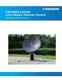
EXPLORER 5075GX
Auto-Deploy Antenna System
Installation and user manual
EXPLORER 5075GX
Installation and user manual
Document number: 98-143492-B
Release date: 7 November 2014
Disclaimer
Any responsibility or liability for loss or damage in connection with the use of this product and the
accompanying documentation is disclaimed by Thrane & Thrane A/S. The information in this manual is
provided for information purposes only, is subject to change without notice and may contain errors or
inaccuracies. Manuals issued by Thrane & Thrane A/S are periodically revised and updated. Anyone
relying on this information should acquire the most current version e.g. from www.cobham.com/satcom >
Service and support, or from the distributor. Thrane & Thrane A/S is not responsible for the content or
accuracy of any translations or reproductions, in whole or in part, of this manual from any other source.
In the event of any discrepancies, the English version shall be the governing text.
Thrane & Thrane A/S is trading as Cobham SATCOM.
Copyright
© 2014 Thrane & Thrane A/S. All rights reserved.
Trademark acknowledgements
• Inmarsat is a registered trademark of the International Maritime Satellite Organisation (IMSO) and is
licensed by IMSO to Inmarsat Limited and Inmarsat Ventures plc.
• Other product and company names mentioned in this manual may be trademarks or trade names of
their respective owners.
ii
98-143492-B
Safety summary
The following general safety precautions must be observed during all phases of operation,
service and repair of this equipment. Failure to comply with these precautions or with specific
warnings elsewhere in this manual violates safety standards of design, manufacture and
intended use of the equipment. Thrane & Thrane A/S assumes no liability for the customer's
failure to comply with these requirements.
Microwave radiation hazards
During transmission the antenna radiates Microwave Power.This radiation may be hazardous to
humans close to the antenna. During transmission, make sure that nobody gets closer than the
recommended minimum safety distance.
The minimum safe distance in front of the antenna reflector is 32 m when in the focal line (a
straight line between the feed horn and satellite), based on a radiation level of 10 W/m2. No
hazard exists at the back of the reflector.
WARNING! This device emits radio frequency energy. Do not place your
head or other body parts between transmitting feed horn and reflector
when the system is operational.
Service
User access to the interior of the antenna is not allowed. Only a technician authorized by
Cobham SATCOM may perform service - failure to comply with this rule will void the warranty.
Power supply
The voltage range for the EXPLORER 5075GX is 100 – 240 VAC (nominal), 4 A, 50/60 Hz.
WARNING! Before disassembling or performing any maintenance or
upgrades, unplug the unit from power source.
Do not operate in an explosive atmosphere
Do not operate the equipment in the presence of flammable gases or fumes. Operation of any
electrical equipment in such an environment constitutes a definite safety hazard.
Keep away from live circuits
Operating personnel must not remove equipment covers. Component replacement and internal
adjustment must be made by qualified maintenance personnel. Do not replace components
with the power cable connected. Under certain conditions, dangerous voltages may exist even
with the power cable removed. To avoid injuries, always disconnect power and discharge
circuits before touching them.
WARNING! Be aware of pinch points while the antenna is being
positioned, deployed or stowed.
Failure to comply with the rules above will void the warranty!
98-143492-B
iii
As per FCC §15.105: Information to the User
NOTE: This equipment has been tested and found to comply with the limits for a Class B digital
device, pursuant to part 15 of the FCC Rules. These limits are designed to provide reasonable
protection against harmful interference in a residential installation. This equipment generates,
uses and can radiate radio frequency energy and, if not installed and used in accordance with
the instructions, may cause harmful interference to radio communications. However, there is
no guarantee that interference will not occur in a particular installation. If this equipment does
cause harmful interference to radio or television reception, which can be determined by turning
the equipment off and on, the user is encouraged to try to correct the interference by one or
more of the following measures:
• Reorient or relocate the receiving antenna.
• Increase the separation between the equipment and receiver.
• Connect the equipment into an outlet on a circuit different from that to which the receiver
is connected.
• Consult the dealer or an experienced radio/TV technician for help.
iv
98-143492-B
Table of contents
Chapter 1
About this manual
1.1 Manual overview ...............................................................................................................1-1
1.1.1 Intended readers .................................................................................................................1-1
1.1.2 Software version ..................................................................................................................1-1
1.1.3 Typography ............................................................................................................................1-1
1.2
Chapter 2
Precautions ............................................................................................................................1-2
Introduction
2.1 EXPLORER 5075GX system ........................................................................................2-1
2.1.1 Overview ..................................................................................................................................2-1
2.1.2 Global Express service .......................................................................................................2-2
2.1.3 Service activation ................................................................................................................2-2
2.2 Description of the system components .........................................................2-3
2.2.1 Antenna positioner .............................................................................................................2-3
2.2.2 RF assembly ...........................................................................................................................2-3
2.2.3 Reflector ..................................................................................................................................2-3
2.2.4 Electronics enclosure and support legs ....................................................................2-4
2.2.5 Keypad and display ............................................................................................................2-5
2.2.6 Web interface for setup and troubleshooting ......................................................2-5
2.2.7 LAN ports and WLAN .........................................................................................................2-6
2.2.8 Power Supply .........................................................................................................................2-6
Chapter 3
Assembly & start up
3.1 What’s in the box .............................................................................................................3-1
3.1.1 To unpack ...............................................................................................................................3-1
3.1.2 Initial inspection ..................................................................................................................3-2
3.2 To assemble the EXPLORER 5075GX .................................................................3-2
3.2.1 Prerequisites ..........................................................................................................................3-2
3.2.2 Assembly .................................................................................................................................3-3
Chapter 4
3.3
Start up with auto-acquisition ...............................................................................3-6
3.4
To stow the antenna .....................................................................................................3-7
3.5
To disassemble and pack the antenna ............................................................3-8
Setup and operation
4.1 Setup using the web interface ...............................................................................4-1
4.1.1 Introduction ..........................................................................................................................4-1
4.1.2 To connect to the web interface .................................................................................4-1
4.1.3 To configure the LAN network ....................................................................................4-6
4.1.4 WLAN settings ......................................................................................................................4-9
4.1.5 To deploy, stow, stop or jog the antenna ............................................................4-10
4.1.6 Navigation ........................................................................................................................... 4-11
4.1.7 Administration ................................................................................................................... 4-12
4.1.8 To set up user permissions (guest login) ..............................................................4-14
4.1.9 To import and export a system configuration ................................................... 4-15
4.1.10 To reset to factory default .......................................................................................... 4-16
98-143492-B
v
Table of contents
4.2 Keypad and display menus .................................................................................... 4-18
4.2.1 Keypad and display ......................................................................................................... 4-18
4.2.2 Navigating the menus .................................................................................................... 4-19
4.2.3 The menu tree ................................................................................................................... 4-19
4.2.4 Brightness of the display .............................................................................................. 4-22
Chapter 5
Service
5.1 General support .................................................................................................................5-1
5.1.1 Preventative maintenance ..............................................................................................5-1
5.1.2 Help desk and diagnostics report ................................................................................5-2
5.1.3 To point with the hand crank ........................................................................................5-3
5.1.4 Reset ..........................................................................................................................................5-4
5.1.5 Satellite profiles and VSAT modem profiles ..........................................................5-5
5.1.6 GX Modem: One Touch Commissioning ..................................................................5-7
5.1.7 Proxy server settings in your browser .......................................................................5-8
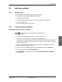
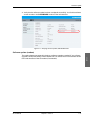
5.2 Software update ................................................................................................................5-9
5.2.1 Prerequisites ..........................................................................................................................5-9
5.2.2 Software update procedure ...........................................................................................5-9
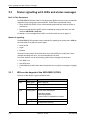
5.3 Status signalling with LEDs and status messages ................................ 5-12
5.3.1 LEDs on the keypad of the EXPLORER 5075GX ................................................. 5-12
5.3.2 Status information of the modem ........................................................................... 5-13
5.4
Appendix A
To return units for repair ........................................................................................ 5-14
Technical specifications
A.1
Antenna characteristics ..............................................................................................A-1
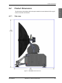
A.2 Product Dimensions .......................................................................................................A-3
A.2.1 Side view .................................................................................................................................A-3
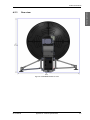
A.2.2 Top view ..................................................................................................................................A-4
A.2.3 Rear view .................................................................................................................................A-5
Appendix B
Appendix C
System messages
B.1
Event messages – overview ......................................................................................B-1
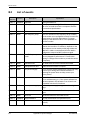
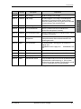
B.2
List of events .......................................................................................................................B-2
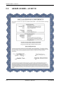
Approvals
C.1
EN 301 489-1 V1.9.2 (2011-09) ..............................................................................C-1
C.2
AS/NZS 22:2009 + A1:20110 ....................................................................................C-2
C.3
FCC Part 15 and ICES-003 .........................................................................................C-3
C.4
Part 15 of the FCC Rules .............................................................................................C-4
Glossary
..............................................................................................................................................................Glossary-1
Index
....................................................................................................................................................................Index-1
vi
98-143492-B
About this manual
1.1
1
Manual overview
This manual has the following chapters:
• Introduction
• Assembly & start up
• Setup and operation
• Service
This manual has the following appendices:
• Technical specifications
• System messages
• Approvals
1.1.1
Intended readers
This is an installation and service manual for the EXPLORER 5075GX system, intended for
users of the system and service personnel. Personnel installing or servicing the system must
be properly trained and authorized by Cobham SATCOM. It is important that you observe
all safety requirements listed in the beginning of this manual, and install the system
according to the guidelines in this manual.
1.1.2
Software version
This manual is intended for EXPLORER 5075GX with software version 1.49. The GX
modem (Core module) software version is shown in its own web interface.
1.1.3
Typography
In this manual, typography is used as indicated below:
Bold is used for the following purposes:
•
To emphasize words.
Example: “Do not touch the antenna”.
•
To indicate what the user should select in the user interface.
Example: “Select SETTINGS > LAN”.
Italic is used to emphasize the paragraph title in cross-references.
98-143492-B
1-1
About this manual
Chapter 1
Precautions
1.2
Precautions
Text marked with “Warning”, “Caution”, “Note” or “Important” show the following type of
data:
• Warning: A Warning is an operation or maintenance procedure that, if not obeyed, can
cause injury or death.
• Caution: A Caution is an operation or maintenance procedure that, if not obeyed, can
cause damage to the equipment.
• Note: A Note gives information to help the reader.
• Important: A text marked Important gives information that is important to the user,
e.g. to make the system work properly. This text does not concern damage on
equipment or personal safety.
All personnel who operate equipment or do maintenance as specified in this manual must
know and follow the safety precautions. The warnings and cautions that follow apply to all
parts of this manual.
WARNING! Before using any material, refer to the manufacturers’
material safety data sheets for safety information. Some materials can be
dangerous.
CAUTION! Do not use materials that are not equivalent to materials
specified by Cobham SATCOM. Materials that are not equivalent can cause
damage to the equipment.
1-2
Chapter 1: About this manual
98-143492-B
Chapter 2
Introduction
2
This chapter has the following sections:
Introduction
• EXPLORER 5075GX system
• Description of the system components
2.1
EXPLORER 5075GX system
2.1.1
Overview
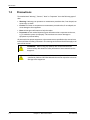
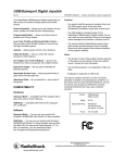
The EXPLORER 5075GX is an auto-deploy 75 cm fly-away antenna system, designed for
operation in the Ka-band. The integrated GX modem, also known as the iDirect Core
Module, commands the system to automatically acquire an operational satellite within five
minutes based on the terminal's GPS location.
All of the EXPLORER series terminals are easy to install, setup, and commission by a nonspecialist technician. The system has the following major components:
1. 2-axis motorized antenna positioner with IFL and BUC power cabling interface ports.
2. Reflector and RF assembly including Filter/Polarizer, BUC, and LNB.
3. Electronics enclosure containing antenna controller (ACU) and Gx modem, keyboard
and display, LAN ports, support legs, and AC power adaptor.
Figure 2-1: Major system components
The antenna provides a stable RF link and the modem provides IP services on the RF link.
The IP services are provided via an Ethernet switch in the antenna subsystem, which is
98-143492-B
2-1
EXPLORER 5075GX system
controlled by the modem. Status information from the modem is provided via the antenna
subsystem. The antenna subsystem can be monitored and software upgraded from the
earth station via the GX modem.
2.1.2
Global Express service
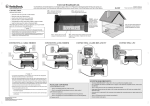
The EXPLORER 5075GX is a unique stabilized GX antenna system operating in the Ka-band
(19.2 to 30 GHz). It is used with the Global Xpress service from Inmarsat, delivering
consistent high-performance download speeds of up to 50 Mbps and 5 Mbps over the
uplink. The following figure shows the coverage map of the GX service at global service
introduction.
Figure 2-2: GX coverage map
2.1.3
Service activation
Before you can start using the EXPLORER 5075GX, you need to activate the system for the
GX service. Contact your service provider for activation.
2-2
Chapter 2: Introduction
98-143492-B
2.2
Description of the system components
2.2.1
Antenna positioner
The auto-deploy antenna positioner can accommodate 4° to 83° of angular movement in
the elevation axis and ± 90° in the azimuth axis. The mechanical assemblies rely on two
independent axes to allow for precise antenna pointing. A ground gradient of up to 12° can
be accommodated with the terminal levelling features. The antenna positioner is rated at
IPX5, it can stay outside in rainy weather.
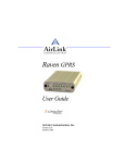
2.2.2
RF assembly
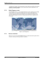
The RF assembly includes the BUC, LNB, reflector hub, filter/polarizer, and feed horn. It also
contains brackets that are attached to mounting blocks on the elevation arms. Once the RF
assembly is mounted, the thumbscrews beneath the blocks hold the brackets securely in
place. Also, the BUC and LNB are mounted closely to the filter/polarizer to reduce the need
for wave guide. This design allows for quick assembly and disassembly of the RF assembly
from the positioner.
Figure 2-3: RF assembly
2.2.3
Reflector
The 75 cm reflector consists of four interchangeable panels and a center hub. The panels
are made entirely of composite with the exception of the latches. The aluminum latches are
used to secure the panels to the hub. Two smaller latches along the edge of the panels
attach the reflector panels to each other. The reflector weighs 3 kg (8.5 lbs). The reflector
98-143492-B
Chapter 2: Introduction
2-3
Introduction
Description of the system components
Description of the system components
has been designed to meet wind load and thermal distortion requirements; see Technical
specifications on page A-1 for more detail.
Figure 2-4: Center hub with four latches for the 4 panels
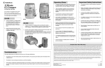
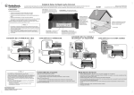
2.2.4
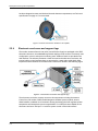
Electronics enclosure and support legs
The modem, Antenna Control Unit (ACU), and AC Power Supply are packaged in the IP65
electronics enclosure. An embedded keypad and display provide access to commonly used
configuration, control, and system monitoring tools. Additional tools are provided in the
web interface. The antenna positioner is hard-mounted to the electronics enclosure, and
internal cables running between them are protected by a water-tight cable gland. Other
important external features of the electronics enclosure are shown in the following figure.
Figure 2-5: Electronics enclosure and support legs
The electronics enclosure contains numerous subcomponents including the Antenna
Control Unit, GX modem, GNSS (Global Navigation Satellite System) module, sensors,
WLAN module, in addition to environment-sensing technology that self-regulates system
temperature and atmospheric pressure equalization. Four LAN ports are available on the
electronics enclosure. LAN port 1 is used for system control via the web interface.
2-4
Chapter 2: Introduction
98-143492-B
Description of the system components
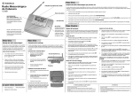
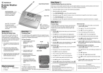
2.2.5
Keypad and display
The menus show how the system has been configured. You can also see events (warnings,
errors and information). Signal strength indication is rendered on the display as 7 blocks on
the main display. The signal strength is also displayed as a number in the sub-menu Manual
Pointing.
0DLQ1$9*+0'01(72./$1±
$&48,6,7,212.
6$7:5;/+7;0$5
Figure 2-6: Keypad and display (detailed, example)
The display has a two line menu system. The display also supports two status lines (Upper
and Lower) for compact satellite and antenna information. For a description of the LED light
indicators see LEDs on the keypad of the EXPLORER 5075GX on page 5-12.
2.2.6
Web interface for setup and troubleshooting
To fully configure the EXPLORER 5075GX, use the built-in web interface. Installation of
software is not necessary, you can use a standard Internet browser. The web interface is
mainly used for first-time setup of the LAN ports, WLAN use and administrating admin and
guest access rights. The web interface is useful when troubleshooting the EXPLORER
5075GX. The web interface can be accessed using WiFi. For details about network
configuration see To configure the LAN network on page 4-6.
Figure 2-7: Web interface, DASHBOARD (example)
98-143492-B
Chapter 2: Introduction
2-5
Introduction
Using the keypad and display you can deploy, stow and stop the antenna, including
monitoring the system (warnings, errors and information). See The menu tree on page 4-19
for a full list of menus.
Description of the system components
2.2.7
LAN ports and WLAN
The electronics enclosure has four LAN connectors (type RJ45) for connecting a PC/lap top
or similar:
• LAN connector on the left-hand side (LAN 1) is used for system control via the web
interface.
• Three connectors (LAN 2 to LAN 4) for user ports for Internet etc., configured by the GX
modem.
The EXPLORER 5075GX has a WLAN module. Access to one of the LAN ports using WLAN
must be set up in the web interface, see To configure the LAN network on page 4-6.
2.2.8
Power Supply
The power adaptor supplies primary power to the electronics enclosure, antenna positioner,
and the BUC. Power input is specified as follows: 100-240 VAC, 4A, 50/60 Hz.
2-6
Chapter 2: Introduction
98-143492-B
Chapter 3
Assembly & start up
3
This chapter has the following sections:
• What’s in the box
• To assemble the EXPLORER 5075GX
• Start up with auto-acquisition
Assembly & start up
• To stow the antenna
• To disassemble and pack the antenna
3.1
What’s in the box
3.1.1
To unpack
The EXPLORER 5075GX antenna system is packaged into two transit cases.
• Case 1 - RF assembly and reflector
• Case 2 - Electronics enclosure and antenna positioner
Figure 3-1: 2 transit cases
Note
98-143492-B
Take care when handling the feed assembly. Do not grab the assembly by the feed
horn. The feed's subreflector can be easily damaged.
3-1
To assemble the EXPLORER 5075GX
Unpack the cases and check that the following items are present:
1. Antenna positioner and electronics enclosure
2. Feed assembly
3. Red (Tx) & Blue (Rx) RF cables
4. Gray BUC Power cable
5. AC Power Adaptor
6. Hand crank
7. CD with user documentation
3.1.2
Initial inspection
Inspect the cases immediately upon receipt for evidence of damage during transport. If the
shipping material is severely damaged or water stained, request that the carrier's agent be
present when opening the cases. Save all packing material for future use.
WARNING! To avoid electric shock, do not apply power to the system
if there is any sign of shipping damage to any part of the front or rear
panel or the outer cover. Read the safety summary at the front of this
manual before installing or operating the system.
After unpacking the system, inspect it thoroughly for hidden damage and loose
components or fittings. If the contents are incomplete, if there is mechanical damage or
defect, or if the system does not work properly, notify your dealer.
3.2
To assemble the EXPLORER 5075GX
3.2.1
Prerequisites
• When operating on uneven surfaces, use the rotating adjustment tube to move the feet
up and down to level the base and achieve stability.
• The terminal may be anchored to the ground to meet operational requirements in high
wind conditions. For anchoring you may add extra weight to the support legs, or insert
stakes through holes on the support feet. The recommended weight values to hold the
terminal to the ground can be provided upon request.
• Place the EXPLORER 5075GX in North-South orientation for best performance during
acquisition.
• Pay attention not to cover the GNSS (GPS, Glonass, etc.) module.
• Pay attention not to cover the WLAN module.
3-2
Chapter 3: Assembly & start up
98-143492-B
Figure 3-2: Position of GNSS and WLAN
Wind speed considerations
The antenna is designed to operate under wind speeds of 48 km/h (30 mph) gusting up to
72 km/h (45 mph) while anchored and survive winds of 100 km/h (62 mph) gusting up to
130 km/h (80 mph) while anchored. Note that the antenna may point away from the
satellite in winds blowing faster than the operational wind speed limit.
Important
Do not assemble or operate the terminal at wind speeds exceeding the
operational wind speeds. In case the wind speeds exceed the operational
wind speed limit while the antenna is already assembled or operational, bring
the antenna to the stow position. In case the wind speeds exceed the survival
wind speed limit while the antenna is already assembled or operational, bring
the antenna manually back to the stow position, disassembled and packed.
In the EXPLORER 5075GX auto-deploy terminal, access points have been provided to access
the azimuth and elevation drives. At higher wind speeds, the antenna can be manually
driven to the stow position using the manual drive tool included in the transport cases. See
also To point with the hand crank on page 5-3.
3.2.2
Assembly
The EXPLORER 5075GX antenna ships from the factory with pre-set and calibrated position
feedback, limit sensing, limit switches, and motor speeds. To be fully operational, you must
only deploy the antenna positioner, install the reflector, and connect the IFL and power
cables between the RF assembly and the electronics enclosure. Then after power-up, the
system will auto-acquire the network within five minutes.
98-143492-B
Chapter 3: Assembly & start up
3-3
Assembly & start up
To assemble the EXPLORER 5075GX
To assemble the EXPLORER 5075GX
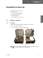
To assemble the EXPLORER 5075GX, do as follows:
1. Unpack the electronics enclosure and place the electronics enclosure upon level ground
and deploy the two support legs.
Figure 3-3: Electronics enclosure and support legs
The two support legs and support feet provide additional stability and prevent
movement of the system.
2. Rotate the fine-tuning rotating adjustment tube on the support legs to move the feet up
and down to level the base and achieve stability.
Figure 3-4: To adjust the support legs
3. You may have to anchor the terminal to the ground to meet operational requirements in
high wind conditions. For anchoring you may add extra weight to the support legs, or
insert stakes through holes on the feet.
4. Unpack the RF assembly, handle it carefully.
Note
Take care when handling the feed assembly. Do not grab the assembly
by the feed horn. The feed's subreflector can be easily damaged.
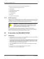
5. Retract the thumbscrews on the mounting blocks, located on the elevation arms.
6. Mount the RF assembly by inserting the brackets down into the mounting blocks
3-4
Chapter 3: Assembly & start up
98-143492-B
Figure 3-5: To mount the antenna positioner
7. Re-engage the thumbscrews to lock the brackets into place.
8. Unpack the four interchangeable panels.
9. Release the four locking mechanisms on the reflector hub, insert the two bottom panels
and re-secure the locking mechanism on the reflector hub.
Figure 3-6: Center hub with four latches for the 4 panels
10.Latch the two bottom panels using the two smaller latches along the edge of the each
panel to carefully secure the reflector panels into place.
Figure 3-7: Latches to interconnect the four panels
11.Insert and latch the two upper panels.
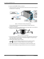
12.Connect the three cables as shown in the following figure:
• BUC Power grey cable to MIL connector
• Tx: IFL RG-6 red cable to BUC's Transmit port
• Rx: IFL RG-6 blue cable to LNB's Receive port.
98-143492-B
Chapter 3: Assembly & start up
3-5
Assembly & start up
To assemble the EXPLORER 5075GX
Start up with auto-acquisition
Figure 3-8: Tx, Rx RF and BUC cables
13.Connect the AC Power Adaptor to the electronics enclosure.
Figure 3-9: AC power connection
14.Use the four RJ-45 ports for making IP-data connections; there are two separate
functions accessible using these ports:
LAN1 (leftmost) for access to the web interface (setup and troubleshooting)
LAN2 to LAN4 for Internet use etc.
Note
3.3
The three standard LAN ports (LAN2 to LAN4) are for Internet and other user data
traffic. The web interface can only be accessed via LAN1. Wi-fi connection must
be configured, see To configure the LAN network on page 4-6 and WLAN settings
on page 4-9.
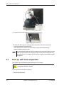
Start up with auto-acquisition
The system is set to automatically point and acquire a connection.
WARNING! Be aware of pinch points while the antenna is being
positioned, deployed or stowed.
To start up the antenna, do the following:
1. Press the On/Off button.
3-6
Chapter 3: Assembly & start up
98-143492-B
To stow the antenna
.
The antenna is fully operational when the display says ACQUISITION OK and the field
MDM: in the upper status line shows NETOK.
If the system is not set to automatically begin pointing after power-on, then the user
may deploy using two alternative methods: using the keypad and display or the web
interface.
Auto-acquisition overview
The following points describe the typical auto-pointing algorithm:
1. Detect Mechanical Home Position for Az and El, which calibrates the encoders.
2. Calculate the Az/El look angles using the inputs from GNSS (GPS, Glonass etc.), Level
sensors, Compass, and inclinometer.
3. Set elevation and azimuth to the calculated look angle.
4. Proceed to maximum value on the satellite signal and achieve LOCK status.
The modem then enters the network and begins passing user traffic. This pointing
algorithm uses Cobham's proven TracStar technology that is currently deployed in
thousands of terminals around the world.
Note
3.4
As a safety precaution, the modem is automatically inhibited from transmitting
until the unit has locked on to the satellite and acquired the network.
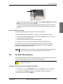
To stow the antenna
The antenna must be set into the stow position before it can be packed into the transport
cases. After stowing the elevation and azimuth are zero degrees.
WARNING! Be aware of pinch points while the antenna is being positioned,
deployed or stowed.
To stow the antenna using the keypad and display
1. Press OK to scroll to the COMMAND page and press OK again to access the page.
2. Press and until STOW is selected, and press OK to initiate the selection.
3. Wait until the status shows STOWED.
98-143492-B
Chapter 3: Assembly & start up
3-7
Assembly & start up
Figure 3-10: On/Off button
To disassemble and pack the antenna
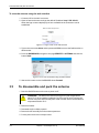
To stow the antenna using the web interface
1. Connect a PC to the LAN1 connector.
2. Open an Internet browser and type the default IP address: http://192.168.0.1.
When the login screen is displayed you have verified that the connection can be
established.
Figure 3-11: Logon screen to the web interface
3. Type in the user name admin and the password 1234 to access the Dashboard as an
administrator.
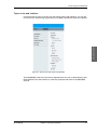
4. From the DASHBOARD, navigate to the page SERVICE > ANTENNA and click the
button Stow.
Figure 3-12: To stow the antenna using the web interface
5. Wait until the status on the DASHBOARD shows Stowed.
3.5
To disassemble and pack the antenna
1. Press the ON/OFF button on the unit to power it off.
WARNING! The electronics enclosure may get very hot (temperatures
above 70° C) in hot weather conditions. Do not move the unit! Touching the
hot unit may cause serious bodily harm. Wait until the unit has cooled down to
temperatures below 50° C.
2. Remove all cables.
3. Dismantle the four reflector panels.
4. Remove the RF assembly from the antenna positioner.
5. Put the parts into the two transport cases.
3-8
Chapter 3: Assembly & start up
98-143492-B
Chapter 4
Setup and operation
4
This chapter has the following sections:
• Setup using the web interface
4.1
Setup using the web interface
4.1.1
Introduction
Use the built-in web interface of the EXPLORER 5075GX to set up the antenna, i.e. setup of
the WLAN and for service and troubleshooting. You can use a standard Internet browser.
A satellite profile with the GX Modem is already set up at the factory. No further profiles are
needed.
Important
The EXPLORER 5075GX is not designed to be connected directly to the
Internet. It must be located behind a dedicated network security device such
as a firewall.
If any ports of the EXPLORER 5075GX are exposed to the Internet you must
change the default passwords as anyone with access and malicious intent can
render the EXPLORER 5075GX inoperable.
4.1.2
To connect to the web interface
To connect to the web interface do as follows:
1. Switch on the EXPLORER 5075GX system. Wait until the LEDs on the front plate show
that the system is ready to be configured.
• Power LED: Green
• Logon LED: Off
• Fail/Pass LED: Flashing green during power-on self test, after that steady green.
2. Connect a PC to the LAN1 connector (Service port, standard Ethernet, leftmost).
You can configure it according to your network requirements. See To configure the LAN
network on page 4-6 for more information.
3. Open your Internet browser and enter the IP address of the EXPLORER 5075GX:
http://192.168.1.2 (default, can be read out in the display).
98-143492-B
4-1
Setup and operation
• Keypad and display menus
Setup using the web interface
When the login screen is displayed you have verified that the connection to the
EXPLORER 5075GX can be established. The web interface is ready for use. You can
continue to configure the system.
Figure 4-1: Logon screen
If you cannot establish a connection there might be problems with the Proxy server
settings of your PC. See Proxy server settings in your browser on page 5-8 for further
information.
4. Type in the user name admin and the password 1234 to access the Dashboard.
There is also a guest login (user name: guest, password: guest). With this login you can
protect the system from accidental changes of the configuration. A guest can only
access the functions that are allowed on the page User permissions by an
administrator. For more information see To set up user permissions (guest login) on
page 4-14.
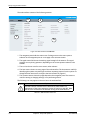
5. The web interface shows the DASHBOARD page.
Figure 4-2: Web interface: DASHBOARD
Acquisition process
The acquisition process is started automatically after power on (factory default). A satellite
and modem profile has been set up at the factory. The antenna is fully operational when
the display shows ACQUISITION OK and the field MDM: in the upper status line shows
NETOK.
4-2
Chapter 4: Setup and operation
98-143492-B
Setup using the web interface
Topics in the web interface
Setup and operation
Use the site map to get an overview over the existing menus and submenus. You can click
on each menu in the site map to go directly to the page or display the respective submenu.
Figure 4-3: Topics in the web interface (SITE MAP)
The DASHBOARD is the first screen that is displayed when the user or administrator enters
the IP address of the web interface. It shows the properties and status of the EXPLORER
5075GX.
98-143492-B
Chapter 4: Setup and operation
4-3
Setup using the web interface
The web interface consists of the following sections:
2
3
4
1
5
Figure 4-4: Web interface: DASHBOARD
1. The navigation pane holds the main menu. Clicking an item in the menu opens a
submenu in the navigation pane or a new page in the contents section.
2. The signal status field shows the tracking signal strength of the antenna. The signal
strength can vary during operation, depending on the current position relative to the
satellite.
3. The icon bar shows icons for active events, when relevant.
4. The host name is shown on every page of the web interface. The host name is useful for
identifying the system at remote login and when requesting reports from the system. To
change the host name see To configure the LAN network on page 4-6.
5. The contents section shows the page selected in the navigation pane. This section is
used for viewing or changing settings, or for performing actions.
The following icon may appear in the icon bar in the web interface:
Icon
Explanation
An event is active. Click the icon to see a list of active events. For
explanations of the event messages, see List of events on page B-2. Note
that this icon will remain in the icon bar as long as the event is active.
Table 4-1: Web interface: Event icon
4-4
Chapter 4: Setup and operation
98-143492-B
Setup using the web interface
To navigate the web interface
• To expand a menu, click the menu in the navigation pane.
• To access status and settings, click the relevant subject in the navigation pane or
click the relevant icon in the icon bar. The status or settings are displayed in the contents
section.
• To get an overview over the submenus available, click SITE MAP in the
navigation pane. Click on items in the site map to go directly to the relevant location.
You can give access to some configuration settings for users that are not
administrators. For information see To set up user permissions (guest login) on
page 4-14.
Note
To connect a PC
1. Connect a PC to LAN1 port (Service port, standard Ethernet, leftmost).
You can configure it according to your network requirements. See To configure the LAN
network on page 4-6 for more information.
2. Open your Internet browser and enter the IP address: http://192.168.1.2 (default).
Information fields on the Dashboard
DASHBOARD
System status
Description
Current status of the EXPLORER 5075GX.
Examples:
Antenna software upload
Antenna POST (Power-On Self Test)
Ready (waiting for data from the modem or no satellite profile
selected)
Deployed idle (antenna ready)
Homing antenna (verifying antenna position)
Early acquisition (acquiring the satellite signal, no modem
communication yet))
Acquiring signal (acquiring the satellite signal, with modem
communication)
Acquisition ok (signal from the GX satellite acquired)
Safe mode (error, followed by an error description)
GPS position
Current position, reported by the GNSS module
Satellite profile
Name of the currently active satellite profile.
Satellite position
Position of the satellite selected in Satellite profile.
Azimuth
Current value for azimuth.
Elevation
Current value for elevation.
RX RF frequency
Ka band receiving frequency, auto-selected by modem
Table 4-2: Web interface: DASHBOARD
98-143492-B
Chapter 4: Setup and operation
4-5
Setup and operation
To connect a PC to the EXPLORER 5075GX do as follows:
Setup using the web interface
DASHBOARD
Description
Tuner signal strength
Current tuner signal strength
Tuner mode
GSC (GX) or Narrowband
Tracking RF frequency
Current RF tracking frequency
Antenna TX allowed
Not allowed or Allowed
Modem RX status
Not locked or Locked
ACU part name, Antenna Part names, serial numbers for ACU and antenna, software
part name, ACU serial
version of the EXPLORER 5075GX.
number, Antenna serial
number, Software
version
Table 4-2: Web interface: DASHBOARD (Continued)
4.1.3
To configure the LAN network
On this page you can enter a host name. The host name helps identifying the EXPLORER
5075GX system. The EXPLORER 5075GX has four 10/100 Mbit Ethernet ports labelled LAN
1, 2, 3 and 4. LAN1 is the service port. LAN2, LAN3 and LAN4 are controlled by the GX
modem.
Important
The EXPLORER 5075GX system is not designed to be connected directly to
the Internet. It must be located behind a dedicated network security device
such as a firewall. If any ports of the EXPLORER 5075GX are exposed to the
Internet you must change the default passwords as anyone with access and
malicious intent can render the EXPLORER 5075GX inoperable.
To configure the LAN network go to SETTINGS > Network.
4-6
Chapter 4: Setup and operation
98-143492-B
Setup and operation
Setup using the web interface
Figure 4-5: Web interface: SETTINGS, Network (default settings)
Important
Make sure that the networks do not use IP address ranges that overlap.
Make the necessary changes on this page and click Apply.
Sections
Preferred use
NETWORK Host The host name is used for identifying the EXPLORER 5075GX. The
name
default host name is acu. You can change the name. Letters (a-z), digits
(0-9) and hyphen (-) are allowed as legal characters.
Note: The host name must start with a letter.
LAN Port 1
LAN port 1 is dedicated as the service port. By default this port has the IP
address http://192.168.1.2; the current value can be displayed in the
EXPLORER 5075GX display.
The service port has 3 modes:
• Static (default).
• DHCP client. Used when the antenna is on a local network.
• Switched with port 5. Used to access the GX modem. This LAN is
internal with static IP configuration (192.168.1.2).
Table 4-3: Setup of LAN network
98-143492-B
Chapter 4: Setup and operation
4-7
Setup using the web interface
Sections
Preferred use
LAN Port 2, 3
and 4
User data ports, configured automatically by the modem. The VLAN
table shows this configuration.
LAN Port 5
No connector, only internal connection.This network is connected to the
modem (iDirect GX Modem). It is set to static IP.
WLAN
The wireless port can be connected to one of the other ports (service
port or one of the user data ports).
Set here which of the ports 1 to 5 you want to access with WiFi.
If LAN Port 1 is selected, you must set it to a static IP address and select
DHCP server.
Table 4-3: Setup of LAN network (Continued)
Static IP or DHCP Client
If you select DHCP client the network IP address and sub-net mask must be provided by a
DHCP server on that network. If you select Static IP address you must specify a unique IP
address and a sub-net mask.
DHCP Server Settings.
On LAN Port 1: Service you can choose to run a DHCP server. Select the check box DHCP
Server. The DHCP server settings are only displayed and can be selected when the port
mode is set to Static, otherwise the DHCP server settings are not shown.
The DHCP start and end addresses must be on the same network as the port's static IP.
VLAN port membership table
The VLAN port membership table is configured by the modem. The table is useful when
troubleshooting.
4-8
Chapter 4: Setup and operation
98-143492-B
Setup using the web interface
4.1.4
WLAN settings
To set up the WLAN access point, do as follows:
Setup and operation
1. Select SETTINGS > WLAN from the left navigation pane.
Figure 4-6: Web interface: SETTINGS > WLAN
2. Enable or disable the WLAN (default: Disabled).
3. Select the Country for your present location.
4. WLAN channel can be changed, channels available depend on the setting for
Country.
5. For Broadcast SSID, select Enabled (default) or Disabled.
Enabled: WLAN access point is shown to other users.
Disabled: WLAN access point is hidden.
6. Type in the SSID of your choice or accept the default SSID, which is Cobham. The
SSID is the name of the wireless local area network. It is a text with maximum 32
characters.
7. Select the Security standard. Select one of the following encryption standards:
• Disabled (default)
• WEP-64, enter the encryption key in hexadecimal format.
• WEP-128, enter the encryption key in hexadecimal format.
• WPA-PSK, enter the encryption key in hexadecimal or text format.
• WPA2-PSK, enter the encryption key in hexadecimal or text format.
8. Type in the Encryption key for the selected Security standard. This is not applicable if
you have selected Security mode None.
9. Click Apply.
98-143492-B
Chapter 4: Setup and operation
4-9
Setup using the web interface
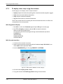
4.1.5
To deploy, stow, stop or jog the antenna
On this page you can deploy, stow or stop the antenna.
• Deploy: Prepare the antenna for pointing after it has been stowed, stopped or jogged.
• Stow: Stow the antenna before disassembly.
• Stop: Stop the antenna immediately.
• Jog: Move the antenna in azimuth and elevation.
There is also a reset button for resetting the azimuth and elevation offset. An offset of 0
corresponds to the current position.
With keypad and display
1. Press OK to scroll to the Command page and press OK again to access page.
2. Press until Deploy is selected, and press OK to initiate the selection.
What to expect during deployment:
The antenna system starts up and goes through a brief initialization procedure:
POWERING UP
ANTENNA POST
MANUAL POINTING
ACQUISITION OK
With the web interface
1. Connect a PC to the LAN1 connector.
2. Open an Internet browser and type the default IP address: http://192.168.0.1, user
name admin and the password 1234.
3. From the DASHBOARD, go to the page SERVICE > ANTENNA.
Figure 4-7: Web interface: SERVICE > Antenna, Deploy
4. Click the button Deploy, Stow or Stop.
5. To jog the antenna click Enable jog mode. Homing must be finished.
4-10
Chapter 4: Setup and operation
98-143492-B
Setup using the web interface
6. Click the arrow buttons for Azimuth or Elevation to change the offset. The current
position is shown on the screen.
Enable line up mode is only used during troubleshooting.
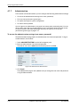
4.1.6
Navigation
On this page you can enter a fixed position or a fixed base heading.
Do as follows:
Setup and operation
1. Select SERVICE > Navigation from the left navigation pane.
Figure 4-8: Web interface: SERVICE > Navigation
2. Set the Position and Orientation:
Item
Description
Position mode GPS - GNSS module is used for current position (default).
Manual - enter values from other position source. (Accuracy should
be better than 50 m.)
Compass mode Automatic - magnetic heading is used (default).
Manual - enter a value for the direction of the EXPLORER 5075GX as
an alternative to the magnetic heading (0 to 360 degrees, precision
±20°).
Table 4-4: Web interface: SERVICE > Navigation
3. Click Apply to save the new settings.
98-143492-B
Chapter 4: Setup and operation
4-11
Setup using the web interface
4.1.7
Administration
In this section of the web interface you can configure the following administrative settings:
• To access the administration settings (user name, password)
• To set up user permissions (guest login)
• To import and export a system configuration
• To reset to factory default
You can logon as an administrator or as guest (user name: guest, password: guest). You can
allow or deny users that are not administrators (user name: guest, password: guest) access
to certain functions and make these pages read-only, see more in To set up user
permissions (guest login) on page 4-14.
To access the administration settings (user name, password)
The Administration settings require an Administration user name and password. To log on
as administrator, do as follows:
1. Select ADMINISTRATION from the left navigation pane.
2. Enter the Administration user name and password.
The default user name is admin and the default password is 1234.
Figure 4-9: Web interface: Administration
3. Click Logon.
The Administration page is now updated to let you change the user name and password
or log off Administration.
4-12
Chapter 4: Setup and operation
98-143492-B
Setup using the web interface
To change the administrator password, do as follows:
Setup and operation
1. After entering the administrator user name and password in the ADMINISTRATION
page, locate the section Change administrator logon.
Figure 4-10: Web interface: Administration, change administrator logon and
password
2. Type in the new password and retype it on the next line.
3. Click Change. At the next logon the new password is required.
To reset the administrator password, do as follows:
1. Contact your service partner for a reset code. Report the serial number of the ACU. You
find it in the Dashboard, ACU serial number.
2. Click the link Forgot administrator password? at the bottom of the
ADMINISTRATOR LOGON page (see Figure 4-9: Web interface: Administration).
Figure 4-11: Web interface: ADMINISTRATION, Reset administrator password
3. Type in the reset code obtained from your service partner and click Reset.
4. Type in the user name admin, the default password 1234 and click Logon.
To log off administration
If you have not entered anything for 30 minutes under ADMINISTRATION, you are
logged off automatically. To log off manually, click Logoff in the ADMINISTRATION
page.
98-143492-B
Chapter 4: Setup and operation
4-13
Setup using the web interface
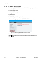
4.1.8
To set up user permissions (guest login)
You can manage user access to certain functions of the EXPLORER 5075GX system. You can
allow or deny users that are not administrators (user name: guest, password: guest) access
to certain functions and make these pages read-only. This is useful if you want to protect
the system against unintended changes or tampering of the system.
Important
Study this screen thoroughly and decide which areas of the EXPLORER
5075GX system you want to give non-administrator users (user name:
guest) access to.
To set up the user permissions for guest users, do as follows:
1. From the left navigation pane, select ADMINISTRATION > User permissions.
Figure 4-12: Web interface: ADMINISTRATION, User permissions
2. For each item under ALLOW USERS TO: select
• Yes to allow the guest user access
• No to block the guest user access to the settings. Then the pages are read-only,
changes cannot be made by the guest user.
Change network: Change IP configuration of the LAN connectors. For further
information see To configure the LAN network on page 4-6.
Operate antenna: Allow to deploy, stow, stop or jog the antenna using the web
interface.
Control Modem: Allow to reset or power cycle the GX modem.
3. Click Apply.
The settings to which access is denied are now greyed out for the guest user.
4-14
Chapter 4: Setup and operation
98-143492-B
Setup using the web interface
4.1.9
To import and export a system configuration
If you need to reuse a configuration in another EXPLORER 5075GX, you can save the
current configuration to a file, which can then be loaded into another EXPLORER 5075GX.
You can also use this feature for backup purposes.
Important
Load and save configurations can only be done with the same software
version in the units involved.
The configuration file contains all the settings you have entered during system setup:
satellite profiles, VSAT modem profiles, LAN setup, user permissions etc.
To save a configuration to a file, do as follows:
Setup and operation
1. Select ADMINISTRATION > Export/import config.
Figure 4-13: Web interface: Administration, Export/import configuration
2. Click the button Export. Follow the download instructions on the screen. You can use
this configuration file for upload into another EXPLORER 5075GX,
To load a configuration from a file, do as follows:
1. Select ADMINISTRATION > Export/import config.
2. Click the button Browse and locate the configuration file (.cfg file) you want to upload.
Then click the button Open.
3. In the web interface click the button Upload.
To clone a system configuration, do as follows:
1. Reset to factory default, see the following section for details.
2. Import a configuration from file, see section above.
98-143492-B
Chapter 4: Setup and operation
4-15
Setup using the web interface
4.1.10
To reset to factory default
When resetting EXPLORER 5075GX to factory default, the following settings are deleted or
reset to factory default:
• All added satellite profiles
• All added VSAT modem profiles
• Changes in the network setup
• User permissions
• Display: brightness setting
To reset to factory default settings, do as follows:
1. From the left navigation pane, select ADMINISTRATION > Factory default.
Figure 4-14: Web interface: ADMINISTRATION > Factory default
2. Click Reset to factory default.
Note
4-16
Calibration data for azimuth and cable calibration are not reset during factory
default.
Chapter 4: Setup and operation
98-143492-B
Setup using the web interface
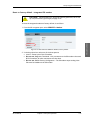
Reset to factory default - integrated GX modem
CAUTION! Administrators only. Close this page for guest users, see To set
up user permissions (guest login) on page 4-14.
To reset the integrated modem to factory default, do as follows:
Figure 4-15: Web interface: SERVICE > Modem, Factory default
2. In the drop-down box select one of the three options:
• Level 0 – Power cycle of the GX modem
• Do not use: Diagnostic Test Mode – Only connection to the GX modem is the serial
RS-232 interface, all other connections are shut down.
• Do not use: Default Factory Configuration – The GX modem stops working. New
files must be loaded into the GX modem.
98-143492-B
Chapter 4: Setup and operation
4-17
Setup and operation
1. From the left navigation pane, select SERVICE > Modem.
Keypad and display menus
4.2
Keypad and display menus
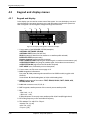
4.2.1
Keypad and display
In the display you can see the current state of the system. You can also deploy, stow and
stop the antenna, see events (warnings, errors and information) and how the system has
been configured. Use the keypad to navigate through the menu tree.
1
2
3
4
5
0DLQ1$9*+0'01(72./$1±
$&48,6,7,212.
6$7:5;/+7;0$5
6
7
8
9
Signal strength
Figure 4-16: Display and keypad of the ACU (example)
1. Current status of the EXPLORER 5075GX (examples):
ANTENNA SOFTWARE UPLOAD
ANTENNA POST (Power-On Self Test)
READY (waiting for data from the modem or no satellite profile selected)
DEPLOYED IDLE (antenna ready)
Homing antenna (verifying antenna position)
EARLY ACQUISITION (acquiring the satellite signal, no modem communication yet))
ACQUIRING SIGNAL (acquiring the satellite signal, with modem communication)
ACQUISITION OK (signal from the GX satellite acquired)
SAFE MODE (error, followed by an error description)
2. Current menu, see The menu tree on page 4-19.
3. NAV: Navigational information
First letter: G (Valid position signal received from the GNSPS module) or g (No valid
GNSS fix)
Second letter: H (Valid heading data) or h (No valid heading data).
4. MDM: Current status of the modem: TEST, ERROR, READY, INIT, RXOK, ACQ,
NETOK, RESET, OFF
5. LAN: LAN connectors used, 1, 2, 3, 4, –.
6. SAT: Longitude, satellite position of the currently active satellite profile.
7. RX:
1 (Rx1 Lock, - or 1),
- (Rx2 Lock, - or 2),
L (RX polarisation of currently active satellite profile: L (left-hand) R (right-hand).
8. RF tracking frequency in GHz and LNB LO Frequency.
9. TX: <Modem TX> <ADU TX> <TX pol>
<Modem TX> = [m,M]
<ADU TX> = [a,A]
<Tx pol>=[-,L,R]
4-18
Chapter 4: Setup and operation
98-143492-B
Keypad and display menus
After 1 hour the display is dimmed to lowest intensity. Press any key to light up the display.
4.2.2
Navigating the menus
Use the keypad to navigate the menus.
• Press OK or to select a menu item.
• Use the arrow keys and to go through the menu items or enter a
number, digit by digit.
• Use the arrow keys and to go through the settings and move
from one digit to the next.
• Press OK to select a setting.
• Press again to move one level up. If applicable, confirm to store the new setting by
pressing OK.
The menu tree
Setup and operation
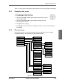
4.2.3
In the menu tree you can see how the system has been configured. To enter satellite
information directly, use a connected PC and the web interface.
0$,1
&200$1'
&200$1'
6723
$17(11$
'(3/2<
02'(0
672:
6$7(//,7(
1(7:25.
$17(11$
32,17,1*
0$18$/32,17,1*
32,17,1*
$17(11$67$7(
(9(176
*36
(/(9$7,21
&203$66
$=,087+
9(56,216
6(5,$/180%(56
*36
/$7,78'(
02'(0
/21*,78'(
02'(07<3(
),;7<3(
7;(1$%/(
5;/2&.
6(5,$/180%(56
6,*1$//(9(/
,0
1(7/('
$&8
67$7/('
7;/('
5;/('
5;/('
3:5/('
7(03/('
)$1/('
6$7(//,7(
1(7:25.
326,7,21
3257,3
5;)5(4
32570$6.
/1%/2
'()$8/7*$7(:$<
%8&/2
0$18$/32,17,1*
(9(17
$=,(/(6,*
(9(17!
(1$%/(',6$%/(
(9(171!
Figure 4-17: Menu tree in the display
98-143492-B
Chapter 4: Setup and operation
4-19
Keypad and display menus
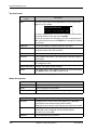
Top-level menu
Top-level
menu
MAIN
Description
View with current status of the EXPLORER 5075GX. Example when
logged on to the satellite:
0DLQ1$9*+0'01(72./$1±
$&48,6,7,212.
6$7:5;/+7;0$5
This view is displayed after a time out of 10 minutes. Press any key
(except left arrow) to enter the menu at MAIN.
New events are shown in this display. If an event is displayed, press
OK to jump directly to the menu EVENTS for viewing the currently
active events.
COMMAND
You can stow, deploy or stop the antenna in this menu.
ANTENNA
Shows the current antenna parameters, position, software version
and serial numbers of the ADU and ACU.
MODEM
Modem information, including modem LED status
SATELLITE
Current satellite information. This information is selected using the
web interface.
NETWORK
Shows the IP addresses and netmasks of the LAN connectors and
the management mask.
MANUAL POINTING To enable and disable manual pointing.
EVENTS
View system events. Active events are shown as: X ACTIVE EVENTS
in the MAIN display. Press OK to update the list.
Table 4-5: Top-level menus
Menu descriptions
COMMAND
Description
STOP
Stops the antenna from moving
DEPLOY
Starts the deployment procedure
STOW
Moves the antenna into the position for packing
Table 4-6: COMMAND menu
ANTENNA
Description
POINTING
ANTENNA STATE: Current state of the antenna, e.g. TRACKING
ELEVATION: Current elevation angle of the antenna
AZIMUTH: Current azimuth of the antenna, with reference to North
GPS
LATITUDE: current latitude, read from GNSS module.
LONGITUDE: current longitude, read from GNSS module.
FIX TYPE: 2D or 3D or NONE
COMPASS
Current orientation of the antenna.
Table 4-7: ANTENNA menu
4-20
Chapter 4: Setup and operation
98-143492-B
Keypad and display menus
ANTENNA
Description
VERSIONS
Current software version.
SERIAL NUMBERS
Serial number of the EXPLORER 5075GX
Table 4-7: ANTENNA menu (Continued)
MODEM
Description
MODEM TYPE
Current modem type.
TX ENABLE
On or off, information delivered by the connected GX modem.
RX LOCK
On or off, information delivered by the connected GX modem.
SIGNAL LEVEL
Current input signal level from the GX modem, in dB.
NET LED
Modem status. Steady or flashing green/yellow/red, OFF
STAT LED
Setup and operation
TX LED
RX1 LED
RX2 LED
PWR LED
TEMP LED
FAN LED
Table 4-8: MODEM menu
SATELLITE
Description
POSITION
Current satellite position.
RX FREQ
Current RX frequency.
LNB LO
LNB LO frequency
BUC LO
BUC LO frequency
Table 4-9: SATELLITE menu
NETWORK
Description
PORT1 IP
Current IP address for LAN1 (service port).
PORT1 MASK
Current netmask for LAN1.
DEFAULT GATEWAY
Current default gateway.
Table 4-10: NETWORK menu
MANUAL POINTING
Description
AZI ELE
Current values for azimuth and elevation
ENABLE/DISABLE
Current status: enabled or disabled
Table 4-11: MANUAL POINTING menu
98-143492-B
Chapter 4: Setup and operation
4-21
Keypad and display menus
EVENT
<EVENT>
Description
In this menu all active events are listed. Use and to go through the
active events.
Events can be of the type WARNING or ERROR.
If a new event occurs or there is a change in the event list while you are in the
EVENTS menu, a * is shown in the upper left corner of the display, next to
the menu name. Press OK to update the EVENTS list, the * will be removed.
A > means the event text is longer than the display. Press > to see the
remaining text.
Table 4-12: EVENTS menu
Example:
4.2.4
EVENT 1/4*: This is the first event out of a list of 4 and there has been a
change in the list. EVENT 1/4 will always be shown, the * indicates that there
has been a change.
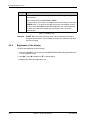
Brightness of the display
To adjust the brightness do the following:
1. Press and hold OK for a short moment until BRIGHTNESS XXX% is displayed (XXX is the
current brightness value).
2. Hold OK + press to brighten or to darken display.
3. Release OK to leave the brightness menu.
4-22
Chapter 4: Setup and operation
98-143492-B
Chapter 5
Service
5
This chapter has the following sections:
• General support
• Software update
• Status signalling with LEDs and status messages
• To return units for repair
5.1
General support
Contact for support
If this manual does not provide the remedies to solve your problem, contact your service
provider.
Preventative maintenance
The EXPLORER 5075GX is constructed to require a minimum amount of regular
maintenance. The following checks should be undertaken on a regular basis:
• Inspect the reflector front surface for physical damage including chips and cracks. Any
substantial damage can affect antenna performance and may require a portion of the
reflector to be replaced.
• Check the feed horn for cracks or damage.
• Use low-pressure washing and soft scrubbing to rinse off grit and reduce wear.
98-143492-B
5-1
Service
5.1.1
General support
5.1.2
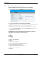
Help desk and diagnostics report
During the installation you can enter the support contact for this installation.
1. To access the Help desk, select HELPDESK from the left navigation pane.
Figure 5-1: Web interface: HELPDESK
2. Click the link, enter support contact information and click Apply.
At Legal notice the licence text for the source code of the parts of the EXPLORER 5075GX
software that fall under free and open source software can be displayed.
You can download a diagnostic report. To generate a diagnostics report do as follows:
1. In the section Download Reports click the button Download. The report (txt file) is
downloaded to your computer.
The Diagnostics report contains information relevant for the service personnel during
troubleshooting. It is also useful documentation of the current setup. It contains all
parameters set during configuration. The main sections are:
• Software
• System
• Hardware
• Setup - System data
• Network - LAN Configuration
• Modems
• Satellites - Satellites profiles
• Operation - Current modem and navigation parameters.
• POST - results of the Power-On-Self-Test
• Active Events - lists the currently active events
• Events - List of all cleared events.
• System log
5-2
Chapter 5: Service
98-143492-B
General support
Event list
When an event is registered, the web interface shows an event icon
in the icon bar as
long as the event is active. The ACU display shows also active events. To view the event list
with active events, click the event icon from the icon bar at the top of the web interface, or
select HELPDESK > Event list from the left navigation pane.
The Event list page shows a detailed list of active events and notifications including the
time of the first occurrence, ID and severity of the event message, and a short text
describing the error. Active events are cleared from the event list when the error is cleared.
They are moved to the section Notifications and are displayed for 24 hours. All entries in
the section Notifications are cleared automatically after 24 hours and after restart of the
system. For a list of all events with description, error code (ID), explanation and remedy see
System messages on page B-1.
Self test
You can start a self test of the EXPLORER 5075GX ADU and ACU.
1. Click Self test in the HELPDESK page.
2. Click the menu item Self test.
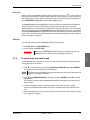
5.1.3
Warning! The EXPLORER 5075GX will reboot to perform the self test.
Rebooting the ACU will terminate all existing connections.
To point with the hand crank
If auto-acquisition is not possible you can use a hand crank to bring the antenna into the
correct position. Do as follows:
1. Press on the keypad to go to the page MANUAL POINTING and select ENABLE.
This page sends a pointing request to the terminal.
Note
Using the inputs from GNSS, the system calculates the azimuth and elevation look
angles for the target GX satellite.
2. Press until ENABLE/DISABLE is selected, and select ENABLE, press OK to initiate
the selection.
The antenna must be in the state MANUAL POINTING. Else, deploy and wait until this
state is shown.
3. Use the included hand-crank for axis movement in the event of a loss in power.
Access to the azimuth and elevation axis ports is located at the lower rear side of the
unit.
4. Insert the Unbraco key (5 mm) into the holes for azimuth and elevation. One turn of the
key is equal to 0.1 degree.
98-143492-B
Chapter 5: Service
5-3
Service
Important
General support
5. Adjust the elevation, based on the ACU’s calculated elevation look angle. The terminal’s
target and current elevation axis angles must match each other as closely as possible.
MACQ-1
NAV:G-
AZI
124.6
SAT: 062.6 E
ELE
12.6
RX:--L
MDM: INIT
12.6
LAN:----
SIG:
198
19.707/18.250
V
TX:maR
Figure 5-2: Target and current elevation axis angles
6. The operator uses the azimuth adjust to detect the GX signal, which is displayed in the
display. Use a compass tool, if needed.
MACQ-1
NAV:G-
AZI
124.6
SAT: 062.6 E
ELE
12.6
RX:--L
MDM: INIT
12.6
LAN:----
SIG:
198
19.707/18.250
V
TX:maR
Figure 5-3: Current signal strength
Note
The best method to manually locate a satellite is typically to sweep in azimuth
slowly back and forth until you peak on the signal.
7. Adjust until the strongest possible signal strength is achieved. For GSC mode: An L
displayed after the signal strength means that the signal is in lock.
5.1.4
Reset
To reset the antenna do the following:
1. Press and hold and until the ACU display shuts down and the antenna reboots.
0DLQ1$9*+0'01(72./$1±
$&48,6,7,212.
6$7:5;/+7;0$5
Figure 5-4: To reset the system
2. Wait until the antenna has rebooted and is operational again. The last active satellite
profile will be used.
To reset the GX modem to factory defaults use the web interface. See Reset to factory
default - integrated GX modem on page 4-17.
Reset to factory defaults using the web interface
You can reset the EXPLORER 5075GX to factory defaults. See To reset to factory default on
page 4-16.
Important
5-4
Warning! Reset to factory default will delete all settings, including
satellite and VSAT modem profiles, network setup, user permissions
and ACU display brightness settings.
Chapter 5: Service
98-143492-B
General support
You can reset the GX modem to factory defaults. See Reset to factory default - integrated
GX modem on page 4-17.
5.1.5
Satellite profiles and VSAT modem profiles
Satellite profiles
A satellite profile with the GX Modem is already setup at the factory. You may add a
satellite profile with the generic modem for troubleshooting purposes. This is done on the
page Satellite profiles.
Service
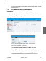
Satellite profiles – New entry and Edit
Figure 5-5: Web interface: SETTINGS - list of satellite profiles (example)
Each satellite profile has one assigned VSAT modem profile.
Figure 5-6: Web interface: SETTINGS, Satellite profiles — new entry (example)
To add or edit a satellite profile, do as follows:
1. Go to SETTINGS or Satellite profiles and click Edit or New entry.
2. Enter or edit the Satellite profile name.
3. Select a VSAT modem profile. The page automatically displays the parameters available
for the selected VSAT modem profile. For instructions how to add a VSAT modem
profile see VSAT modem profile – New entry and Edit on page 5-6.
4. Enter the data for the satellite, if any. For satellite data see www.lyngsat.com.
98-143492-B
Chapter 5: Service
5-5
General support
• FCC (FCC §25.205): 5 degrees
5. Click Apply to save the settings for the satellite profile.
VSAT modem profiles
On the page VSAT modem profiles you create, edit or delete VSAT modem profiles. The
VSAT modem profile GX Modem is already set up at the factory. It is useful for
troubleshooting to create a VSAT modem profile with the Generic modem.
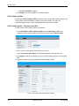
VSAT modem profile – New entry and Edit
To add or edit a VSAT modem profile, do as follows:
1. Go to SETTINGS > VSAT modem profiles and click New entry or Edit. The
supported VSAT modem profiles are listed in the drop-down list VSAT modem.
Figure 5-7: Web interface: SETTINGS, VSAT modem profile – supported modems
2. Fill in a VSAT modem profile name of your own choice.
3. Select the Generic GX modem (for troubleshooting) from the drop down list.
4. Click Apply to add the new profile to the list of VSAT modem profiles or to accept the
edits.
For a generic modem you enter all parameters in the satellite profile.
Figure 5-8: Satellite profile with generic GX modem
5-6
Chapter 5: Service
98-143492-B
General support
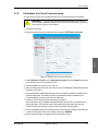
5.1.6
GX Modem: One Touch Commissioning
In some cases you may have to make the One Touch Commissioning for the modem.
WARNING! For your safety: Active RF transmission may occur during an
OTC procedure. Software updates may also occur, yet the system is in receiveonly mode during such auto-updates.
1. Connect a PC to LAN1.
Service
2. Enter the web interface (via Firefox browser) and go to SETTINGS > Network.
Figure 5-9: Setup for One-touch commissioning
3. Under LAN Port 1:Service, select Switched with port 5 from the Mode drop-down
list to be able to access the modem via Port 1.
4. Set the IP address of the PC to 192.168.1.10.
5. Open a Firefox Internet browser and connect to the Core Module Unified Web interface,
type http://192.168.1.1.
6. The Core Module Unified Web interface of the GX modem will ask for the default User
Name and Password. The modem (iDirect Core Module) will know that One Touch
Commissioning has not yet occurred on this terminal.
7. Find the menu for One Touch Commissioning and start it.
Once commissioning is completed the antenna will search for the I5 satellite with the
highest elevation. The antenna will find the satellite and the modem with the core
module will perform necessary steps to enter the network (SW upgrades).
8. The Unified Web Interface of the Core Module will indicate the modem in the network
as well as the modem status in the display in the menu MODEM.
9. When commissioning is completed, test all subscribed services.
98-143492-B
Chapter 5: Service
5-7
General support
5.1.7
Proxy server settings in your browser
If you are connecting your computer using a LAN or WLAN interface, the Proxy server
settings in your browser must be disabled before accessing the web interface. Most
browsers support disabling of the Proxy server settings for one specific IP address, so you
can disable Proxy server settings for the web interface only, if you wish. Consult your
browser help for information.
To disable the use of a Proxy server completely, do as follows:
Note
The following description is for Microsoft Internet
Explorer. If you are using a different browser, the
procedure may be different.
1. In Microsoft Internet Explorer, select Tools > Internet Options > Connections >
LAN Settings.
2. Clear the box labeled Use a proxy server for your LAN.
3. Click OK.
When the proxy server settings are disabled, close and restart your browser. You may need
to change this setting back on return to your Internet connection.
5-8
Chapter 5: Service
98-143492-B
Software update
5.2
Software update
5.2.1
Prerequisites
The following items are required to make a software update:
• One computer with a standard Ethernet port available.
• A standard Internet browser.
• 1024×768 pixels or higher display resolution (best viewed with small fonts).
• One straight LAN cable.
• Access to the file with the new software.
5.2.2
Software update procedure
EXPLORER 5075GX without GX modem
Note
Software update should only be done by qualified service
personnel.
1. Power up the EXPLORER 5075GX system, i.e. switch on the ACU.
If you want to use another LAN port to access the web interface you must configure it
according to your network requirements. See To configure the LAN network on page 46 for more information.
3. Open your Internet browser and enter the IP address of the EXPLORER 5075GX. The
default IP address is http://192.168.1.2.
4. Type in the user name admin and the password 1234 to access the Dashboard.
5. The web interface shows the DASHBOARD page.
6. Click SERVICE in the navigation pane. The UPLOAD SOFTWARE TO TERMINAL
page is displayed.
98-143492-B
Chapter 5: Service
5-9
Service
2. Connect a PC to LAN interface 1 (Service port, standard Ethernet).
Software update
Figure 5-10: Software update with the web interface
7. Click Browse... and locate the new software file.
8. Click Upload.
Important
Do not browse away from the upload page. This will terminate the
upload process. Wait for the browser to reload automatically.
9. You can select Enable automatic rollback on failure, then the system returns to the
previous software if the installed software fails.
10.Click Switch to this version if you want to force the system to use the alternative
software version stated in the display.
Note that the upload procedure takes a couple of minutes. When done, the ACU
automatically restarts with the new software version.
The start-up procedure after a software upload takes longer than the usual start-up time,
as the software in the antenna must also be updated. The display shows: ANTENNA
SW UPLOAD.
If software upload fails - how to recover
To recover from a failed software upload, turn off the ACU and turn it on again. Then repeat
the upload procedure as described in Software update on page 5-9.
To verify the software update
1. The software version can be viewed in the DASHBOARD window of the web interface.
2. After completing the software update procedure, the EXPLORER 5075GX will perform a
POST (Power On Self Test).
3. When the POST has finished, the green Pass/Fail LED on the keypad must become
steadily green. Verify that the Pass/Fail LED is not red nor flashing orange once every 2
seconds. Wait until the Pass/Fail LED is green.
5-10
Chapter 5: Service
98-143492-B
Software update
4. Verify that the software update has been completed successfully. You find the software
version number in the DASHBOARD window of the web interface.
Figure 5-11: Verifying software update, SAILOR 900 VSAT
The modem detects automatically whether a software upgrade is needed. If yes, software
upgrade is done automatically via the satellite link. You can see the current software version
in the web interface of the GX modem (Core Module).
98-143492-B
Chapter 5: Service
5-11
Service
Software update (modem)
Status signalling with LEDs and status messages
5.3
Status signalling with LEDs and status messages
Built-In Test Equipment
The EXPLORER 5075GX has a Built-In Test Equipment (BITE) function in order to make fault
diagnostics easy during service and installation. The BITE test is performed during:
• Power On Self Test (POST), which is automatically performed each time the system is
powered on.
• Person Activated Self Test (PAST), which is initiated by starting a self test in the web
interface HELPDESK > Self test.
For details on error messages after a POST or a self test see Event list on page 5-3.
Means of signalling
The EXPLORER 5075GX provides various methods for signalling the system status. LEDs on
the front panel of the ACU are used to signal:
• Power on/off
• Logon
• Fail/Pass
The built-in web interface of the ACU shows any events (BITE error codes) with a short
message describing each error. This is also displayed in the ACU.
In an error situation, one of the following system status messages may be shown:
• ACU POST error
• ADU POST error
• SAFE MODE (plus information about the specific error, see System messages on page B1).
5.3.1
LEDs on the keypad of the EXPLORER 5075GX
There are 3 LEDs: Power, Logon and Fail/Pass LED.
LED
Power
Logon
Behaviour
Description
Steady green
Power supply OK
Steady red
Power supply failure
Off
No power
Flashing green
Current status is displayed:
• Searching satellite
• Identifying satellite
• Carrier lock & TX enabled from modem
Steady green
Satellite link established
Off
No satellite link acquired
Table 5-1: LEDs on the ACU
5-12
Chapter 5: Service
98-143492-B
Status signalling with LEDs and status messages
LED
Fail/Pass
LED
Behaviour
Description
Steady red
A fault which prevents operation is present
in the system (ACU, ADU, MODEM).
Flashing green
A Power On Self Test (POST) or Person
Activated Self Test (PAST) in progress. The
current status is displayed.
Flashing red
Active BITE failure or warning. The event is
shown in the ACU display.
Steady green
No faults.
Table 5-1: LEDs on the ACU (Continued)
5.3.2
Status information of the modem
The modem status is shown in the display of the EXPLORER 5075GX in the menu Modem
and also in short form in the upper status line. The current status is communicated by a text
string: Steady green, red or yellow, or flashing green, red or yellow.
• NET LED
• STAT LED
• TX LED
Service
• RX1 LED
• RX2 LED
• PWR LED
• TEMP LED
• FAN LED
98-143492-B
Chapter 5: Service
5-13
To return units for repair
5.4
To return units for repair
Should your Cobham SATCOM product fail, please contact your dealer or installer, or the
nearest Cobham SATCOM partner. You will find the partner details on
www.cobham.com/satcom where you also find the Cobham SATCOM Self Service Center
web-portal, which may help you solve the problem.
Your dealer, installer or Cobham SATCOM partner will assist you whether the need is user
training, technical support, arranging on-site repair or sending the product for repair.
Your dealer, installer or Cobham SATCOM partner will also take care of any warranty issue.
5-14
Chapter 5: Service
98-143492-B
Technical specifications
A
This appendix has the following sections:
• Antenna characteristics
• Product Dimensions
A.1
Antenna characteristics
Ka-Band
Receive
Transmit
Feed
2 Port Circular
Frequency Range (GHz)
19.2 - 20.2
29 - 30
Gain (dBi ± 0.2)
41.0
44.5
Axial Ratio (dB)
1.5
1.0
Polarization
LHCP
RHCP
G/T - Comm @ 30° EL, Midband (dB/°K)
17.3
EIRP @ Midband (dBW)
51.5
BUC power (P linear) (Watts)
5
Reflector
Size
75cm
Optics
Axis-Symmetric
Construction
4-Piece Segmented
Mechanical characteristics
98-143492-B
Axis Drive System
2-Axis Positioner
Mount Geometry
Elevation over Azimuth
Travel:-Azimuth
± 90° from stow position
Travel:-Elevation
4° to 83°
Emergency Drive
Hand crank on Az & El
A-1
Technical specifications
Appendix A
Antenna characteristics
Power requirement
100-240VAC, 4A, 50/60Hz 150W (max)
Weights and measures
Terminal
28.6 kg (63 lbs)
Transport inside 2 cases
<31.7 kg (<70 lbs) per case, Airline
checkable
Environmental characteristics
A-2
Wind Speed - Operational
48 km/h (30 mph) gusts up to 72 km/h (45
mph) (anchored)
Temperature - Operational
-25° to +55°C (-13° to +131°F)
Temperature - Survival
-40° to +80°C (-40° to +176°F)
Rain
<100 mm/hr
Humidity
0 to 100% (condensing)
IP Class
IPX5
Appendix A: Technical specifications
98-143492-B
A.2
Product Dimensions
The dimensions shown below reflect the space needed to accommodate the full range of
motion in elevation and azimuth.
A.2.1
Side view
Figure A-1: EXPLORER 5075GX side view
98-143492-B
Appendix A: Technical specifications
A-3
Technical specifications
Product Dimensions
Product Dimensions
A.2.2
Top view
Figure A-2: EXPLORER 5075GX top view
A-4
Appendix A: Technical specifications
98-143492-B
Product Dimensions
Rear view
Technical specifications
A.2.3
Figure A-3: EXPLORER 5075GX rear view
98-143492-B
Appendix A: Technical specifications
A-5
Product Dimensions
A-6
Appendix A: Technical specifications
98-143492-B
Appendix B
System messages
B
System messages
This appendix has the following sections:
• Event messages – overview
• List of events
B.1
Event messages – overview
The EXPLORER 5075GX detects events during
• POST (Power On Self Test) – a self test performed at every power-up.
• PAST (Person Activated Self test) – started in the web interface
• CM (Continuous Monitoring) – automatically performed while the system is in
operation.
When the EXPLORER 5075GX detects an event that requires your action, it issues an event
message and the red Fail/Pass LED in the LED panel of the ACU is lit. As long as an event is
active, it is shown in the ACU displayControl Panel the web interface (in HELPDESK > Event
list or click the event icon on the DASHBOARD).
Note
Active events and notifications are shown. As soon as the
event is cleared, it is not displayed any longer. It is then moved
to the Notifications section. Notifications are cleared after 24
hours.
State the Event ID when contacting your service partner.
The event description might contain a number of digits in brackets, e.g. (00000005). This is
supplemental information and used for service and diagnostics purposes.
98-143492-B
B-1
List of events
B.2
Error
code (ID)
List of events
Severity
Description
Explanation
08065-0 WARNING GNSS data
Missing GPS data (fix).
08067-0 ERROR
ADM temperature too high. The ACU is not equipped
with a fan, so make sure there is compliance with the
environmental specifications.
PCB temperature
0806A-0 WARNING VMU connection
The ACU has lost connection with the sat modem.
0806C-0 ERROR
VMU frequency setup
There is a mismatch in the frequency setup. Probably
the sat modem is not configured correctly to match the
requirements of the ACU and antenna. A common
mismatch is the absence of Rx or Tx LO parameter in
the VSAT modem.
0806E-0 ERROR
VMU 10 MHz reference
The VMU Rx or Tx reference signal is not present.
Whether this error Rx or Tx reference, depends on the
users selection on the modem profile page. Make sure
VMU Rx/Tx cable is connected and that the VMU is
configured to output the RX/TX reference signal.
08078-0 WARNING VMU TX frequency
invalid
VSAT modem unit provided a TX frequency of zero.
This may degrade tx performance. To remove this
warning re-configure the modem to provide the correct
tx frequency.
08107-0 ERROR
ADM FPGA load
The ADM FPGA cannot be initialised and loaded.
0810A-0 ERROR
ADM production data
Production data has been corrupted.
0810C-0 ERROR
File system integrity
One or more file system partitions are corrupt. You may
have lost your settings and collected statistics. If
restarting the system does not help, contact your
service partner.
0810D-0 ERROR
Antenna communication Link to the ACU could not be established. Either the
ACU is malfunctioning, or - if the system software has
just been updated - the software is too old and is not
compatible with the ACU hardware.
08800-0 ERROR
Internal power supply
An internal power supply voltage is outside its legal
range.
08840-0 WARNING Master PLL lock
The master PLL has lost lock. Check the input reference
signal.
08841-0 ERROR
The internal tuner PLL was unable to lock.
Tuner lock
08842-0 WARNING GSC demodulator
The GSC demodulator has reported an error.
08843-0 WARNING DVBS demodulator
The DVBS demodulator cannot be initialised and loaded
correctly.
Table B-1: Event messages
B-2
Appendix B: System messages
98-143492-B
List of events
Severity
Description
Explanation
08844-0 WARNING BUC voltage
The BUC voltage is out of range.
08845-0 WARNING LNB voltage
The LNB voltage is out of range. The LNB might be
switched off to protect the power supply circuitry.
Reactivate satellite profile to try again, check LNB cable
and surroundings if the problem persists.
08880-0 ERROR
WLAN configuration error Configuration of WLAN module failed.
08A00-0 WARNING GX Core Module fan
There is a problem with the Core Module fan.
Check/clean and replace if necessary.
08A01-0 WARNING GX Core Module heater
There is a problem with the Core Module heater. Check
and replace if necessary.
08A02-0 WARNING GX Core Module
temperature
The Core Module temperature is out of range. It may
affect performance, and it will be shut down if the
situation gets worse.
08A03-0 ERROR
GX Core Module
The ACU detected a warning/error in the GX Core
Module. Info:
0x00000001: Power supply error
0x00000002: Test
error
09000-0 ERROR
KDM 3V3 supply
Internal 3V3 voltage supply error in the KDM.
09001-0 ERROR
KDM 12V supply
Internal 12V voltage supply error in the KDM.
09002-0 ERROR
KDM display
Display hardware error in the KDM.
09010-0 ERROR
KDM link/SW version
Link to the KDM module could not be established. Either
the KDM board is malfunctioning, or - if the system
software has just been updated - the software is too old
and is not compatible with the KDM hardware.
Table B-1: Event messages (Continued)
98-143492-B
Appendix B: System messages
B-3
System messages
Error
code (ID)
List of events
Event ID Severity
Description
Explanation
0C001
Error
Compass/dish
Not seeing the compass
0C002
Error
GNSS position/velocity Not detecting any GPS satellite
0C003
Error
Base angle level
Antenna base angle exceeds 8°. Level the antenna
0C005
Error
AZ major over travel
Antenna has been driven beyond the azimuth electrical
limit
0C006
Warning AZ over travel
Antenna has reached the electrical limit
0C007
Error
SSI values are not being received
0C008
Warning EL over travel
Antenna has reached the electrical limit
0C009
Error
AZ motor movement
Not detecting any azimuth motor movement
0C010
Error
EL motor movement
Not detecting any elevation motor movement
0C011
Error
Low elevation
Antenna is reporting low elevation fault
0C013
Error
No transponder found
The acquisition algorithm could not identify a
transponder
SNR communication
Table B-2: Event messages of antenna
B-4
Appendix B: System messages
98-143492-B
Appendix C
Approvals
C
This appendix lists the approvals for EXPLORER 5075GX.
EN 301 489-1 V1.9.2 (2011-09)
Approvals
C.1
98-143492-B
C-1
AS/NZS 22:2009 + A1:20110
C.2
C-2
AS/NZS 22:2009 + A1:20110
Appendix C: Approvals
98-143492-B
FCC Part 15 and ICES-003
FCC Part 15 and ICES-003
Approvals
C.3
98-143492-B
Chapter C: Approvals
C-3
Part 15 of the FCC Rules
C.4
C-4
Part 15 of the FCC Rules
Chapter C: Approvals
98-143492-B
Glossary
Glossary
Glossary
1
A
ABS
ADU Bus Slave
ADM
ACU Digital Module. A main processor board in the ACU.
AMB
Antenna Module Bus
B
BUC
Block Up Converter. The BUC can be thought of the “transmitter”, and its actions are
effectively the direct opposite to the LNB. The BUC consists of the Up Converter and HPA.
C
CM
Continuous Monitoring
D
DVB
Digital Video Broadcasting, a set of standards relating to digital television.
F
FPGA
Field Programmable Gate Array
G
GNSS
Global Navigation Satellite System, e.g. GPS.
GPS
Global Positioning System. A system of satellites, computers, and receivers that is able to
determine the latitude and longitude of a receiver on Earth by calculating the time
difference for signals from different satellites to reach the receiver.
GX
Global Xpress, high-speed broadband network, a worldwide Ka-band mobile satellite
system.
I
IFL
Inter-Facility Link
IMSO
International Mobile Satellite Organisation. An intergovernmental organisation that
oversees certain public satellite safety and security communication services provided via
the Inmarsat satellites.
98-143492-B
Glossary-1
Glossary
IP
Internet Protocol. The method or protocol by which data is sent from one computer to
another on the Internet.
K
KDM
Keyboard and Display Module of the ACU
L
LAN
Local Area Network
LED
Light Emitting Diode
LNB
Low Noise Block. A device used to amplify or boost the weak received signal without
amplifying the noise signals (hence the “low noise” part of LNB) and to convert the high
frequencies of the signal into lower frequencies, a process called down converting, for
conveyance to the indoor equipment (demodulator) for processing.
P
PAST
Person Activated Self Test
POST
Power On Self Test. A system test that is activated each time the system is powered on.
R
RF
Radio Frequency. Electromagnetic wave frequencies between about 3 kHz and about 300
GHz including the frequencies used for communications signals (radio, television, cellphone and satellite transmissions) or radar signals.
S
SSID
Glossary-2
Service Set IDentifier. An SSID is the name of a wireless local area network (WLAN). All
wireless devices on a WLAN must use the same SSID in order to communicate with each
other.
98-143492-B
Index
Index
access
limit, 4-14
acquisition
search pattern, 4-2
activation
service, 2-2
ACU display
description, 4-18
admin
password, 4-2
user name, 4-2
administration
settings, 4-12
administrator
log off, 4-13
logon, web interface, 4-12
password, 4-12
password, change, 4-13
password, reset, 4-13
antenna
anchor, 3-4
warnings, B-4
antenna errors, B-4
antenna positioner, 2-3
approvals
AS/NZS 22:2009 + A1:20110, C-2
EN 301 489-1 V1.9.2 (2011-09), C-1
FCC Part 15 and ICES-003, C-3
Part 15 of the FCC Rules, C-4
auto-acquisition, 3-7
B
BITE test, 5-12
Broadcast SSID, 4-9
browser settings
for web interface, 5-7
C
cable
calibration data reset, 4-16
cables, 3-2
connect, 3-5
98-143492-B
calibration
satellite data, 5-5
calibration data, 4-16
reset, 4-16
center hub
panels, 3-5
change administrator password, 4-13
change network setting, 4-14
configuration
copy, 4-15
export, 4-15
import, 4-15
LAN network, 4-6
site map, 4-3
step-by-step, 4-1
Configuration program, 4-1
connect
cables, 3-5
web interface, 4-1
contact information, 5-1
core module
web interface, 5-7
Country
selecting for WLAN, 4-9
Index
A
2
D
default
reset to factory settings, 4-16
deploy, 4-14
hand crank, 5-3
web interface, 4-10
DHCP client, 4-8
DHCP server, 4-8
diagnostic report, 5-2
display
ACU, description, 4-18
description, 2-5
E
encryption key, 4-9
WLAN, 4-9
error codes, B-1
error messages, 5-3, B-1, B-2
Index-1
Index
errors
antenna, B-4
events, B-1, B-2
antenna, B-4
list of active, 5-3
export configuration, 4-15
J
jog, 4-14
web interface, 4-10
K
F
factory default
calibration data, 4-16
reset, 4-16
factory defaults
reset to, 5-4, 5-5
firewall, 4-6
fixed position, 4-11
G
guest
password, 4-2
permissions, 4-14
user name, 4-2
guest login, 4-2, 4-14
GX modem
generic, 5-6
GX service
data rates, 2-2
keypad
description, 2-5
L
LAN
network setup, 4-6
LAN configuration
DHCP client, 4-8
LAN network
configuration, 4-6
LED, 5-12
limit access to web interface, 4-14
LO frequencies, 4-18
load
configuration, 4-15
log off
administrator, 4-13
login
guest, 4-14
web interface, 4-2
logon
administrator, web interface, 4-12
H
hand crank
degree per turn, 5-3
host name, 4-4, 4-6
hub latches, 2-4
M
messages, B-1
microwave radiation, -iii
modem
reset, 4-14
I
import configuration, 4-15
IP address
for web interface, 4-1, 5-9
static, 4-8
IP rating, 2-3
Index-2
N
navigation, 4-4
navigation in web interface, 4-5
network
LAN setup, 4-6
notifications, 5-3
98-143492-B
Index
One Touch Commissioning, 5-7
orientation, 3-2
P
panels
attach to center hub, 3-5
password
administrator, 4-12
change, 4-13
PAST, 5-12
permissions
user, 4-14
Person Activated Self Test, 5-12
position
fixed, 4-11
POST, 5-12
Power On Self Test, 5-12
power supply, 2-6
protect access to settings, 4-14
Proxy server, disabling, 5-7
R
radiation, -iii
recover
software update, 5-10
reflector, 2-3
weight, 2-3
reset, 5-4, 5-5
factory default, 4-16
password, 4-13
reset administrator password, 4-13
reset keys on ACU, 5-4
RF assembly, 2-3
S
safety summary, -iii
satellite data
calibration, 5-5
save
configuration, 4-15
security
WLAN, 4-9
98-143492-B
security key
wireless network, 4-9
self test, 5-3
service activation, 2-2
service port
IP address, 4-1
setup
user permissions, 4-14
site map, 4-3
software update, 5-9
recover, 5-10
software version, 1-1
verify, 5-11
specifications, A-1
SSID, 4-9
static IP, 4-1
static IP address, 4-8
status messages, 5-12
stop, 4-14
antenna, web interface, 4-10
stow, 4-14
antenna, 3-7
web interface, 4-10
support
contact information, 5-1
support legs, 2-4, 3-4
system
ACU reset, keys to press, 5-4
system configuration
copy, 4-15
System messages, B-1
Index
O
T
technical data, A-1
troubleshooting
diagnostic report, 5-2
U
updating software, 5-9
upload
configuration, 4-15
user permissions, 4-14
setup, 4-14
Index-3
Index
V
VLAN port membership table, 4-8
W
warning messages, B-1
warnings, 5-3, B-2
antenna, B-4
warranty, 5-14
web interface
browser settings, 5-7
connect, 4-1
connection, 3-6
core module, 5-7
login, 4-2
navigating, 4-5
overview, 2-5
Wifi
encryption key, 4-9
name, 4-9
wireless local area network
name, 4-9
WLAN
country code, 4-9
encryption key, 4-9
security, 4-9
setup, 4-8
WLAN access point
setup, 4-9
Index-4
98-143492-B
98-143492-B
www.cobham.com/satcom