1
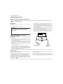
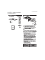
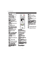
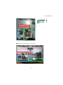
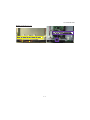
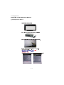
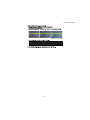
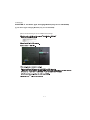
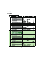
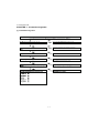
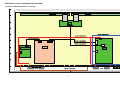
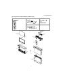
TopPage LC-32LE244E/144E SERVICE MANUAL No. S62X332LE244E LCD COLOUR TELEVISION LC-32LE244E MODELS LC-32LE144E In the interests of user-safety (Required by safety regulations in some countries) the set should be restored to its original condition and only parts identical to those specified should be used. CONTENTS SAFETY PRECAUTION IMPORTANT SERVICE SAFETY PRECAUTION ............................................................i Precautions for using lead-free solder ...............ii End of life disposal ............................................ iii CHAPTER 5. Software Update Method [1] Software Update Method ...............................5-1 CHAPTER 1. OPERATION MANUAL [1] OPERATION MANUAL .................................. 1-1 CHAPTER 7. TroubleShootingTable [1] TroubleShooting Table...................................7-1 CHAPTER 2. Precaution when you open back cabinet [1] Precaution when you open back cabinet........ 2-1 CHAPTER 8. Key Component on MB [1] Key Component on MB .................................8-1 CHAPTER 3. WB Adjustment Method [1] WB Adjustment Method ................................. 3-1 CHAPTER 4. The Panel Type Changing Method (only for LC-32LE244E) [1] The Panel Type Changing Method (only for LC-32LE244E) ............................................... 4-1 CHAPTER 6. Hotel Mode [1] Hotel Mode ....................................................6-1 CHAPTER 9. OVERLL WIRING/BLOCK DIAGRAM [1] OVERALL WIRING DIAGRAM (LC32LE244E).....................................................9-1 [2] OVERALL WIRING DIAGRAM (LC32LE144E).....................................................9-2 [3] SYSTEM BLOCK DIAGRAM .........................9-3 Parts Guide Parts marked with " " are important for maintaining the safety of the set. Be sure to replace these parts with specified ones for maintaining the safety and performance of the set. This document has been published to be used for after sales service only. The contents are subject to change without notice. LC-32LE244E/144E LC32LE244E SAFETY PRECAUTION Service Manual IMPORTANT SERVICE SAFETY PRECAUTION Service work should be performed only by qualified service technicians who are thoroughly familiar with all safety checks and the servicing guidelines which follow: WARNING • 1. For continued safety, no modification of any circuit should be attempted. Use an AC voltmeter having with 5000 ohm per volt, or higher, sensitivity or measure the AC voltage drop across the resistor. • Connect the resistor connection to all exposed metal parts having a return to the chassis (antenna, metal cabinet, screw heads, knobs and control shafts, escutcheon, etc.) and measure the AC voltage drop across the resistor. All checks must be repeated with the AC cord plug connection reversed. (If necessary, a nonpolarized adaptor plug must be used only for the purpose of completing these checks.) Any reading of 1.05 V peak (this corresponds to 0.7 mA peak AC.) or more is excessive and indicates a potential shock hazard which must be corrected before returning the monitor to the owner. 2. Disconnect AC power before servicing. CAUTION: FOR CONTINUED PROTECTION AGAINST A RISK OF FIRE REPLACE ONLY WITH SAME TYPE FUSE. DVM AC SCALE BEFORE RETURNING THE RECEIVER (Fire & Shock Hazard) 1.5k ohm 10W Before returning the receiver to the user, perform the following safety checks: 3. Inspect all lead dress to make certain that leads are not pinched, and check that hardware is not lodged between the chassis and other metal parts in the receiver. 0.15 µF TEST PROBE 4. Inspect all protective devices such as non-metallic control knobs, insulation materials, cabinet backs, adjustment and compartment covers or shields, isolation resistor-capacitor networks, mechanical insulators, etc. 5. To be sure that no shock hazard exists, check for leakage current in the following manner. • Plug the AC cord directly into a 220~240 volt AC outlet. • Using two clip leads, connect a 1.5k ohm, 10 watt resistor paralleled by a 0.15µF capacitor in series with all exposed metal cabinet parts and a known earth ground, such as electrical conduit or electrical ground connected to an earth ground. TO EXPOSED METAL PARTS CONNECT TO KNOWN EARTH GROUND /////////////////////////////////////////////////////////////////////////////////////////////////////////////////////////////////////////////////////////////////////////////////////////////////////////////////////////////////////////// SAFETY NOTICE Many electrical and mechanical parts in LCD color television have special safety-related characteristics. For continued protection, replacement parts must be identical to those used in the original circuit. These characteristics are often not evident from visual inspection, nor can protection afforded by them be necessarily increased by using replacement components rated for higher voltage, wattage, etc. The use of a substitute replacement parts which do not have the same safety characteristics as the factory recommended replacement parts shown in this service manual, may create shock, fire or other hazards. Replacement parts which have these special safety characteristics are identified in this manual; electrical components having such features are identified by “ ” and shaded areas in the Replacement Parts List and Schematic Diagrams. /////////////////////////////////////////////////////////////////////////////////////////////////////////////////////////////////////////////////////////////////////////////////////////////////////////////////////////////////////////// i LC-32LE244E/144E Precautions for using lead-free solder Employing lead-free solder • “PWBs” of this model employs lead-free solder. The LF symbol indicates lead-free solder, and is attached on the PWBs and service manuals. The alphabetical character following LF shows the type of lead-free solder. Example: L F a/a LFa Indicates lead-free solder of tin, silver and copper. Indicates lead-free solder of tin, silver and copper. Using lead-free wire solder • When fixing the PWB soldered with the lead-free solder, apply lead-free wire solder. Repairing with conventional lead wire solder may cause damage or accident due to cracks. As the melting point of lead-free solder (Sn-Ag-Cu) is higher than the lead wire solder by 40 °C, we recommend you to use a dedicated soldering bit, if you are not familiar with how to obtain lead-free wire solder or soldering bit, contact our service station or service branch in your area. Soldering • As the melting point of lead-free solder (Sn-Ag-Cu) is about 220 °C which is higher than the conventional lead solder by 40 °C, and as it has poor solder wettability, you may be apt to keep the soldering bit in contact with the PWB for extended period of time. However, Since the land may be peeled off or the maximum heat-resistance temperature of parts may be exceeded, remove the bit from the PWB as soon as you confirm the steady soldering condition. Lead-free solder contains more tin, and the end of the soldering bit may be easily corroded. Make sure to turn on and off the power of the bit as required. If a different type of solder stays on the tip of the soldering bit, it is alloyed with lead-free solder. Clean the bit after every use of it. When the tip of the soldering bit is blackened during use, file it with steel wool or fine sandpaper. • Be careful when replacing parts with polarity indication on the PWB silk. Lead-free wire solder for servicing Part No. ZHNDAi123250E ZHNDAi126500E ZHNDAi12801KE Description J J J φ0.3mm 250g (1roll) φ0.6mm 500g (1roll) φ1.0mm 1kg (1roll) Code BL BK BM ii LC-32LE244E/144E End of life disposal End of life disposal iii LC-32LE244E/144E CHAPTER 1. OPERATION MANUAL LC32LE244E Service Manual [1] OPERATION MANUAL 1–1 LC-32LE244E/144E 1–2 LC-32LE244E/144E 1–3 LC-32LE244E/144E Service Manual CHAPTER 2. Precaution when you open back cabinet LC32LE244E [1] Precaution when you open back cabinet 2–1 LC-32LE244E/144E Details information related to wire forming 2–2 LC-32LE244E/144E spacer (PSPAZC831WJZZ) 2–3 LC-32LE244E/144E 2–4 LC-32LE244E/144E CHAPTER 3. WB Adjustment Method LC32LE244E Service Manual [1] WB Adjustment Method Remote Remote 3–1 LC-32LE244E/144E 3–2 LC32LE244E Service (only Manualfor LC-32LE244E) CHAPTER 4. The Panel Type Changing Method LC32LE244E [1] The Panel Type Changing Method (only for LC-32LE244E) Please do the following in case of a MAIN board exchange. the the 4–1 LC32LE244E CHAPTER 5. Software Update Method LC32LE244E Service Manual [1] Software Update Method 1 2 3 4 5 Note: At the time of DTV and external input mode, it can update from the pop up menu displayed at the time of USB insertion. 6 the 7 Confirm the software version. MENU ψ SETUP ψ System information 5–1 LC-32LE244E/144E CHAPTER 6. Hotel Mode LC32LE244E Service Manual [1] Hotel Mode 6–1 LC-32LE244E/144E 6–2 LC-32LE244E/144E CHAPTER 7. TroubleShootingTable LC32LE244E Service Manual [1] TroubleShooting Table 7–1 LC-32LE244E/144E 7–2 LC-32LE244E/144E 7–3 LC-32LE244E/144E 7–4 LC-32LE244E/144E 7–5 LC-32LE244E/144E 7–6 LC-32LE244E/144E 7–7 LC-32LE244E/144E 7–8 LC-32LE244E/144E 7–9 LC-32LE244E/144E CHAPTER 8. Key Component on MB LC32LE244E Service Manual [1] Key Component on MB 8–1 LC-32LE244E/144E - MEMO - 8–2 LC-32LE244E/144E CHAPTER 9. OVERLL WIRING/BLOCK DIAGRAM LC32LE244E Service Manual [1] OVERALL WIRING DIAGRAM (LC-32LE244E) J S-PWB S-PWB I CNF1 H G CON2 F CN1 P202 P201 CN2 E CON1 CN1 LED D CN6 CN2 C B R L CN9 R A 1 2 3 4 5 6 7 8 9 10 11 9–1 12 13 14 15 16 17 18 19 LC-32LE244E/144E [2] OVERALL WIRING DIAGRAM (LC-32LE144E) J CNF1 CNF2 I H G CON2 F CN1 P202 P201 CN2 CON1 E CN1 LED D CN6 CN2 C B R L CN9 R A 1 2 3 4 5 6 7 8 9 10 11 9–2 12 13 14 15 16 17 18 19 LC-32LE244E/144E [3] SYSTEM BLOCK DIAGRAM J I H G F E D C B A 1 2 3 4 5 6 7 8 9 10 11 9–3 12 13 14 15 16 17 18 19 LC-32LE244E/144E - MEMO - 9–4 LC-32LE244E/144E PartsGuide PARTS GUIDE No. S62X332LE244E LCD COLOUR TELEVISION LC-32LE244E MODELS LC-32LE144E CONTENTS [1] PRINTED WIRING BOARD ASSEMBLIES [3] CABINET AND MECHANICAL PARTS [2] LCD PANEL MODULE UNIT [4] SUPPLIED ACCESSORIES/ PACKING PARTS Parts marked with " " are important for maintaining the safety of the set. Be sure to replace these parts with specified ones for maintaining the safety and performance of the set. This document has been published to be used for after sales service only. The contents are subject to change without notice. LC-32LE244E/144E NO. PARTS CODE PRICE NEW PART RANK MARK DELIVERY DESCRIPTION [1] PRINTED WIRING BOARD ASSEMBLIES ! N N N N N N RUNTKB031WJZZ2 RUNTKB015WJZZ2 RUNTKB016WJZZ2 RUNTKB017WJZZ2 RUNTKB018WJZZ2 RUNTKB022WJQZ BH AZ AM AM BD N N N N N N P P P P P P MAIN Unit POWER Unit LED DRIVER Unit KEY Unit IR RECEIVER Unit LCD CONTROL Unit (only for LC-32LE244E) N N N N P P P P LCD PANEL MODULE Unit (for LC-32LE244E) LCD PANEL Unit (for LC-32LE244E) LCD PANEL MODULE Unit (for LC-32LE144E) LCD PANEL Unit (for LC-32LE144E) [2] LCD PANEL MODULE UNIT N N N N CLCDTA266FM01 RLCDTA266WJZZ CLCDTA267FM01 RLCDTA267WJZZ DE CM 2 LC-32LE244E/144E [3] CABINET AND MECHANICAL PARTS CNF1/CNF2 (for LC-32LE144E) A B 20 4 R C D E CON2 L 32" LCD Panel Module Unit KEY Unit 21 15 6 3 16 CN1 B P202 12 9 MAIN Unit 10 CON2 LCD CONTROL CNF1 Unit (only LC-32LE244E) E 11 D 16 CNF1 CNF1/CNF2 P202 22 1 CN1 6 6 P201 C P201 8 13 LED DRIVER Unit 21 7 POWER Unit R 23 14 L 2 A 2-6 2-1 2-3 5 18 2-9 2-6 2-4 2-6 2-7 3 LC-32LE244E/144E NO. PARTS CODE PRICE NEW PART RANK MARK DELIVERY DESCRIPTION [3] CABINET AND MECHANICAL PARTS ! ! 1 2 2-1 2-3 2-4 2-6 2-7 2-9 3 4 5 6 7 8 8 9 9 10 11 12 13 14 15 16 18 20 21 22 23 LANGKD629WJ1W CCABBC135WJ11 GCABBC135WJ1A JBTN-A976WJ1A LANGKD624WJ1W PSPAHC590WJZZ PSPAHC592WJZZ XEBS830P08000 GCOVAE449WJ1A LHLDWA294WJUZ LHLDWA318WJKZ LX-BZA207WJF7 PSPANA050WJZZ QACCKA063WJPZ QACCBA113WJPZ QCNW-M816WJPZ QCNW-M878WJPZ QCNW-M817WJPZ QCNW-M818WJPZ QCNW-M819WJPZ QCNW-M820WJPZ QCNW-M821WJPZ QCNW-M823WJZZ RSP-ZA570WJZZ TLABNC117WJZZ TLABZD268WJZZ XBPS830P06WS0 XEBS730P10000 XEBS830P08000 N N N N N N AA N AC AD AA AM N N N N N N N N N N N N N AA AA AA P P P P P P P J P J J J P P P P P P P P P P P J P P J J J Bottom Bracket Rear Cabinet Ass'y Rear Cabinet KEY Button VESA Angle, x2 Spacer, x4 Spacer, x2 Screw, x2 Side Cover Wire Holder, x8 Cable Clamp Screw, x16 LEDD PWB Spacer AC CODE (except for U.K.) AC CODE (for U.K.) Connecting Cord (LVDS) (for LC-32LE244E) Connecting Cord (LVDS) (for LC-32LE144E) Connecting Cord (MAIN-KEYIR) Connecting Cord (MAIN-SP) Connecting Cord (MAIN-PSU) Connecting Cord (PSU-LEDDR) Connecting Cord (LEDDR-LED) FFC, x2 (for LC-32LE244E) Speaker, x2 Model Label Energy Label (Except Russia) Screw, x5 Screw, x2 Screw, x9 4 LC-32LE244E/144E [4] SUPPLIED ACCESSORIES/PACKING PARTS X3 X1 X4 X5 X6 X7 X8 X9 X2 X2-1 X2-2 S5 X7 S6 X4 X8 X2 X5 X9 X6 S2 X3 S3 X1 S1 S4 S9 5 LC-32LE244E/144E NO. PARTS CODE PRICE NEW PART RANK MARK DELIVERY DESCRIPTION [4] SUPPLIED ACCESSORIES/PACKING PARTS X1 X2 X2-1 X2-2 X3 X4 X4 X4 X5 X6 X7 X8 X8 X9 S1 S1 S2 S3 S4 S5 S6 S9 CDAI-A839WJ11 CSAKHA072WJ01 Not Available Not Available RRMCGB042WJSA2 TINS-F523WJZZ TINS-F525WJZZ TINS-F526WJZZ TINS-F524WJZZ TINS-F527WJZZ TINS-F567WJZZ TGAN-A801WJN1 TGAN-B651WJZZ TGAN-A802WJN1 SPAKCG865WJZZ SPAKCG894WJZZ SPAKPB873WJZZ SPAKXD718WJZZ SPAKXD719WJZZ SSAKAA111WJZZ SSAKHA072WJ01 TLABME431WJZZ N N N N N N N N N - N N N N N N N P P P P P P P P P P P P - Stand Base Ass'y Stand Screw Ass'y Screw, x4 "AAA" Size Battery, x2 Remote Control Unit OperationManual (W-EU) (for Europe(SEEP)) OperationManual (E-EU) (for East Europe) OperationManual (R) (for Russia) OperationManual (N-EU) (for Europe(SEEP)) OperationManual (E) (Except Russia) OperationManual (E-EU-2) (for East Europe) Guarantee Sheet (for U.K.) Guarantee Sheet (for Russia) Guarantee Sheet (for U.K.) Paking Case (for LC-32LE244E) (NOT REPLACEMENT ITEM) Paking Case (for LC-32LE144E) (NOT REPLACEMENT ITEM) Polyethylene Bag (NOT REPLACEMENT ITEM) Pad Top (NOT REPLACEMENT ITEM) Pad Bottom (NOT REPLACEMENT ITEM) Polyethylene Bag (NOT REPLACEMENT ITEM) Packing Add. (Screw) (NOT REPLACEMENT ITEM) Paper Label (NOT REPLACEMENT ITEM) 6 LC-32LE244E/144E LC-32LE244E/144E COPYRIGHT © 2012 BY SHARP CORPORATION ALL RIGHTS RESERVED. No Part of this publication may be reproduced, stored in a retrieval system, or transmitted in any from or by any means, electronic, mechanical, photocopying, recording, or otherwise, without prior written permission of the publisher. Jun. 2012 SH. DS SHARP CORPORATION AV Systems Group CS Promotion Center Yaita,Tochigi 329-2193, Japan