1
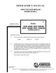
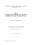
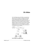
MERLIN
COMMUNICTIONS SYSTEM
SERVICE MANUAL
MODELS 206 AND 410
American Bell
Advanced Information Systems
An AT&T Company
SERVICE MANUAL
MERLIN ✽
COMMUNICATIONS SYSTEM
MODELS 206 AND 410
* Trademark of AT&T Co.
©
1983 Western Electric
All Rights Reserved
Printed in U.S.A.
Issue G, August 1983
999-501-135 AB
CONTENTS
INTRODUCTION
HOW TO USE THIS MANUAL
1
PREINSTALLATION
3
INTRODUCTION
3
IMPORTANT TELEPHONE NUMBERS
3
GETTING STARTED
A. Checking the Floor Plan
B. Checking the Shipment
C. Getting the Tools You Need
4
4
5
5
CIB CROSS REFERENCE
INSTALLATION
11
13
INSTALLING THE CONTROL UNIT
Environmental Requirements
A. Positioning the Control Unit
B. Installing the Cartridges
C. Supplying Power to the Control Unit
D. Connecting the Control Unit to the Network Interface
E. Setting the Control Unit Switches
“Tone-Pulse” Switch
“Ringing” or “Outward Calls” Switches
13
14
14
15
15
15
19
19
20
INSTALLING THE CORDS/CABLES
A. Installing the Voice Terminal Extension Cords
B. Voice Terminal Cabling
Getting Started
Planning and Arranging the Control Unit and Jacks
Installing the Cable
Labeling the Cables
Installing the Jacks at the Control Unit Location
Fastening the Cable(s)
Installing the Jacks at the Voice Terminal Location
C. Installing the Voice Terminals
Getting Started
Assembling the Voice Terminals
20
20
21
22
23
23
24
25
25
26
26
26
27
TESTING PREPARATION
28
TESTING THE VOICE TERMINALS
29
TESTING THE SYSTEM
30
LABELING THE VOICE TERMINAL INTERCOM NUMBERS
32
SYSTEM CHANGES
35
INTRODUCTION
35
TO CHANGE CONTROL UNIT SWITCHES
35
TO ADD AN OUTSIDE LINE
35
TO ADD A VOICE TERMINAL
36
TO ADD A VOICE TERMINAL ACCESSORY
36
TO MOVE A VOICE TERMINAL LOCATION
37
TO SWAP VOICE TERMINAL LOCATIONS
37
TO ADD A CARTRIDGE
37
QUICK CHECK TESTS
39
INTRODUCTION
39
QUICK CHECKS TO DETERMINE WHETHER THE TROUBLE IS IN YOUR
SYSTEM
39
SYMPTOM-BASED QUICK CHECKS
Symptom List
A . Voice Terminal Does Not Ring
Basic Service
Feature Package 1 Service
B. Cannot Make an Outside Call
Basic Service
Feature Package 1 Service
C. Trouble with Indicator Lights, Speaker, or Ringing
D. Some Custom Features Do Not Work
E. All Voice Terminals Have No Lights and No Dial Tone (Entire System
Down)
41
41
41
41
41
41
41
42
42
43
GENERAL QUICK CHECKS
44
IF TROUBLE REMAINS
45
MAINTENANCE EXCHANGE PROCEDURES
INTRODUCTION
44
46
INTRODUCTION
HOW TO USE THIS MANUAL
This Service Manual provides instructions for installing, changing and adding, troubleshooting, and, if necessary, replacing components on your MERLIN* communications system. It is
intended for use by the person in your company who is responsible for telephone service.
Reading the whole manual is not necessary; you need only read the introduction and those
sections relevant to the task you have to perform.
This manual is divided into five sections:
●
●
●
●
●
Preinstallation: Contains instructions to prepare for the installation of your MERLIN
communications system.
Installation: Contains instructions for installation and preliminary testing of your
MERLIN communications system.
System Changes: Provides directions for changing and adding to your MERLIN communications system.
Quick Check Tests: Describes simple tests to identify the source of problems your
MERLIN communications system may have.
Maintenance Exchange Procedures: Describes how American Bell allows you to
exchange faulty equipment for working replacements.
Note:
Notices required by the FCC are printed in the User’s Guide inside the front and
back covers. You should be familiar with this information before installing your
new equipment.
Descriptive and operational information is provided in the User’s Guide. Customer Information Brochures (CIBs) describe the physical characteristics of each device and provide installation instructions. One CIB is packaged with each voice terminal or other system component. Both the CIB and this manual are required for proper component installation.
* Trademark of AT&T Co.
1
2
PREINSTALLATION
PREINSTALLATION
INTRODUCTION
If you are installing your own MERLIN communications system, use the instructions in the
“Preinstallation” and “Installation” sections. These instructions are divided as follows:
●
Getting Started
●
Installing the Control Unit
●
Installing the Cords/Cables
●
Installing the Telephones (Voice Terminals)
●
Testing the Telephones (Voice Terminals)
●
Testing the System
●
Labeling the Telephone (Voice Terminal) Intercom Number
Whenever you see a DANGER, Warning, or Caution, please read it carefully. These
terms mean the following:
●
DANGER — Possibility of personal injury.
●
Warning — Possibility of equipment damage.
●
Caution — Possibility of service interruption.
IMPORTANT TELEPHONE NUMBERS
●
●
For questions concerning installation or repair, call the American Bell toll-free
HELP number:
1-800-628-2888
To order equipment from the National Sales Center, call the American Bell toll-free
SALES number:
1-800-247-1212
3
GETTING STARTED
This section helps you get ready to install your MERLIN communications system. Begin by
checking the floor plan that you prepared with your order, verifying the equipment received,
and getting the tools you need. After you complete each step, check it off in the box on the
left.
A.
❑
Checking the Floor Plan
Check the floor plan that you prepared when you ordered your system, to make sure
that it agrees with the layout of the installation location. Figure 1 show a typical system.
10–BUTTON
VOICE TERMINAL
D8AF TERMINAL
EXTENSION
CORD
MODEL 206 CONTROL UNIT
NETWORK
INTERFACE
MODULAR
LINE
CORDS
D8W MODULAR
TERMINAL CORD
Figure 1
4
Preinstallation (cont’d)
B. Checking the Shipment
❑
Open all packages and make sure you have all the items you ordered. Use your copy of
the order form to check your shipment.
For help in identifying items, refer to Figure 2 (Illustrated Parts List). If there are any
discrepancies, call your sales representative or the HELP number provided in the “Introduction” section.
Note 1:
Do not discard Customer Information Brochures (CIBS) included with items in
your shipment. These instructions may be referred to in this Manual. To avoid
losing the instructions, keep them with the items until you need to use them.
Note 2:
Do not discard the cartons and packaging material. You may have overlooked a
small item, or you may need the cartons and packing to return damaged or defective items.
Note 3:
Save the extra serial number tags loosely packed with the control unit, voice terminals, and cartridges.
C. Getting the Tools You Need
Get the following tools:
❑ 1.
❑ 2.
❑ 3.
Hammer
❑ 4.
Stapler and staples appropriate for attaching wiring to baseboard.
Screwdriver
Drill and appropriate bits, 5/8-inch and smaller (if control unit, voice terminals, or the
extra-alert switch are to be mounted on a wall, or if you must route wiring through
walls).
5
(6A)
CONTROL UNIT
DOOR
(6110-CU1)
4-LINE/10-TERMINAL
CONTROL UNIT
(6106-CU1)
2-LINE/6-TERMINAL
CONTROL UNIT
MOUNTING
HOLES
TEMPLATE
MOUNTING
SCREWS
EXPANSION
BOLTS
MOUNTING
BRACKET
BASE PLATE
(CS 100A) CONTROL UNIT
WALL MOUNTING KIT (61201)
Figure 2 (1 of 6)
6
Preinstallation (cont’d)
(110A) FEATURE
CARTRIDGE (TYPE I)
(6100-FC1)
(150A) MUSIC-ON-HOLD
CARTRIDGE (TYPE II)
(6101-MOH)
(170A) EXTRA–ALERT/2-LINE
POWER FAILURE CARTRIDGE
(TYPE III) (6103-EAP)
(7302 H01) 5-BUTTON VOICE
TERMINAL (3160-111)
(151A) MUSIC-ON-HOLD/PAGING
CARTRIDGE (TYPE II)
(6102-MHP)
(171A) EXTRA–ALERT/4-LINE
POWER FAILURE CARTRIDGE
(TYPE III) (6104-EAP)
(7303 H01) 10-BUTTON VOICE
TERMINAL (3161-172)
(7305 H01) 34-BUTTON VOICE
TERMINAL (3162-412)
Figure 2 (2 of 6)
7
(10A) 5-BUTTON AND 10-BUTTON
VOICE TERMINAL DESK STAND
(32004)
(11A) 10-BUTTON VOICE TERMINAL
ADJUSTABLE DESK STAND
(32002)
(14A) 5-BUTTON VOICE TERMINAL
DESK STAND AND WALL MOUNT
(32000)
(11C) 34-BUTTON VOICE TERMINAL
ADJUSTABLE DESK STAND
(32003)
(201A) 10-BUTTON VOICE
TERMINAL WALL MOUNT
(32001)
(203A) 34-BUTTON VOICE
TERMINAL WALL MOUNT
(32006)
Figure 2 (3 of 6)
8
Preinstallation (cont’d)
(CS 500DM) POWER FAILURE
ROTARY TELEPHONE (61209)
(502A) HEADSET ADAPTER
(3164-HFA)
(CS 2500DMG) POWER FAILURE
“TOUCH-TONE” TELEPHONE (61210)
(S102A) HANDS-FREE UNIT
(3163-HFU)
(335A) AUXILIARY POWER UNIT
(3165-APU)
Figure 2 (4 of 6)
9
(349A) ACOUSTIC COUPLER
ADAPTER (R)
(346A) ACOUSTIC COUPLER
ADAPTER (N) (31710)
(DIW) VOICE TERMINAL
CABLING (32910)
(D8W) MODULAR TERMINAL CORD
(7, 14 AND 25 FT)
(32807, 32814 AND 32825)
(D4CH) MODULAR LINE CORD
(7, 14 AND 25 FT)
(61407, 61414 AND 61425)
(D8AF) TERMINAL EXTENSION CORD
(14, 25, 50, 75 AND 100 FT)
(32914, 32925, 32950, 32975
AND 32900)
D4CE CORD
267A
ADHESIVE-BACKED CABLE CLIP
(267C) TWO-LINE ADAPTER
(61400)
(267A ADAPTER/D4CE-50 CORD)
NETWORK BRIDGING ADAPTER KIT (61401)
Figure 2 (5 of 6)
10
Preinstallation (cont’d)
(452A) EXTRA–ALERT CONTROL
SWITCH (32630)
(103A) CUSTOMER–INSTALLABLE
JACK (32601)
(D181233) LINE–POWERED EXTRA–
ALERT E1CM RINGER (61211)
Figure 2 (6 of 6)
CIB CROSS REFERENCE
The following table provides a cross reference between the Customer Information Brochure
(CIB) number, Apparatus Code, Description, and Price Element Code (PEC) for components
used in the MERLIN communications system, Models 206 and 410.
11
CIB
NUMBER
APPARATUS
CODE
2822H1
953A
2851
CS 100A
Control Unit Wall Mounting Kit
2852
7302 H01
5-Button Voice Terminal
3160-111
2853
7303 H01
10-Button Voice Terminal
3161-172
2854
10A
5- and 10-Button Voice Terminal Fixed Desk Stand
32004
2855
11A
10-Button Voice Terminal Adjustable Desk Stand
32002
2856
201A
10-Button Voice Terminal Wall Mount
32001
2858
103A
Customer-Installable Jack
32601
2863
267C
Two-Line Adapter
61400
2864
S102A
2865
7305 H01
2866
DESCRIPTION
PEC
Tool
61201
Hands-Free Unit
3163-HFU
34-Button Voice Terminal
3162-412
335A
Auxiliary Power Unit
3165-APU
2867
502A
Headset Adapter
3164-HFA
2869
110A
Feature Cartridge (Type I)
6100-FC1
2870
150A
Music-on-Hold Cartridge (Type II)
6101-MOH
2871
151A
Music-on-Hold/Paging Cartridge (Type II)
6102-MHP
2872
170A
Extra-Alert/2-Line Power Failure Cartridge (Type III)
6103-EAP
2873
171A
Extra-Alert/4-Line Power Failure Cartridge (Type III)
6104-EAP
2885
14A
5-Button Voice Terminal Fixed Desk Stand and
Wall Mount
32000
2886
11C
34-Button Voice Terminal Adjustable Desk Stand
32003
2887
203A
34-Button Voice Terminal Wall Mount
32006
2888
267A/D4CE-50
Line Bridging Adapter Kit (Adapter/Cord)
61401
2893
452A-50
Extra-Alert Control Switch
32630
2903
349A
Acoustic Coupler Adapter
—
2923
346A
Acoustic Coupler Adapter
31710
2924
D181233
Line-Powered Extra-Alert E1CM Ringer and Parts
61211
12
INSTALLATION
INSTALLATION
INSTALLING THE CONTROL UNIT
This section explains how to position the control unit, install the cartridges, supply power to
the control unit, connect the control unit to the network interface, and set the control unit
switches (Figure 3).
LOCAL TELEPHONE
EXCHANGE SERVICE
COMPANY
NETWORK
INTERFACE
LOCAL
TELEPHONE
EXCHANGE
SERVICE
COMPANY
LINES
D4CH MODULAR
LINE CORDS
AC
OUTLET
TWO–
LINE
ADAPTER
AC
POWER
CORD
Figure 3
13
Enviromental Requirements
The control has the following requirements:
1. Operating temperatures 40-104 degres Fahrenheit (4-40 degrees Centigrade).
2. Humidity (not to exceed 80 percent).
3.
Dissipation of power (20 watts during normal operation).
4.
Ventilation (a minimum of 1/2 inch of space is required on all sides; also keep away
from extreme heat such as furnaces, heaters, attics, and direct sunlight).
5. Exposure (avoid exposure to moisture, corrosive gasses, dust, chemicals, or other similar materials).
A. Positioning the Control Unit
Determine where the control unit is to be located. Its dimensions are 9-3/8 inches high, 141/4 inches wide, and 9-7/8 inches deep. The control unit weighs 11 pounds.
❑ 1.
If you choose a horizontal surface such as a shelf or cabinet, place the control unit in
the desired location.
If you choose to mount the unit on a wall, find the CS 100A Control Unit Wall Mounting Kit in the shipment and follow the instructions packed with it.
❑ 2.
If the installation includes an auxiliary power unit (335A Power Unit), find it in the
shipment. Install it following the instructions packed with it.
Note 1: A Model 206 system can have a maximum of six voice terminals. An auxiliary
power unit is required when the system has a total of nine or more voice terminals and accessories (for example, five terminals and four hands-free units).
Note 2: A Model 410 system can have a maximum of ten voice terminals. An auxiliary
power unit is required when Model 410 has a total of fifteen or more voice terminals and accessories (for example, ten terminals and six hands-free units).
14
Installation (cont’d)
B. Installing the Cartridges
❑ 1.
Find the optional cartridge(s) you ordered in your shipment. The possible cartridges
are:
●
Feature Package 1 Cartridge (Type I )
●
Music-on-Hold Cartridge (Type II)
●
Music-on-Hold/Paging Cartridge (Type II)
●
Extra-Alert/2-Line Power Failure Transfer Cartridge (Type III)
●
Extra-Alert/4-Line Power Failure Transfer Cartridge (Type III) (Model 410 only)
Two cartridges of the same type (I, II, III) cannot be used simultaneously.
❑ 2.
If you have any cartridges to install, unplug the power cord of the control unit.
Warning:
Do not insert or remove cartridges with power on.
❑ 3. Install the cartridge(s) following the instructions packed with each cartridge. If a
Feature Package 1 cartridge is installed, be certain that the “Ringing” switch label is
covered by the “Outward Calls” label, shipped with the cartridge.
C. Supplying Power to the Control Unit
DANGER:
Any electrical outlet should be installed by a licensed electrician. The requirements are: 117-volt, 60-Hz, 3-prong outlet
that provides a separate ground, separately fused at 15 amps,
and not controlled by a light switch.
Caution:
Do not use an extension cord to supply power to the control
unit.
❑ 1. Plug the power cord into the ac outlet. The green “Power” light in the upper left
corner of the control unit should be on; the red “Warning” light should come on
momentarily to show that it is working and then go off. If the green “Power” light
does not come on, check the outlet. If the outlet is working properly and the green
light remains off, call the HELP number (1-800-628-2888).
❑ 2. If the red “Warning” light does not light momentarily or if it remains on, call the
HELP number (1-800-628-2888).
D. Connecting the Control Unit to the Network Interface
❑ 1.
Locate the network interface (that is, the place where the local telephone exchange
service company lines enter the building). The interface may look like one of the following (Figure 4):
15
625–TYPE CONNECTING BLOCK
(NOTICE DOES NOT
APPLY TO “MERLIN”
INSTALLATION)
625–TYPE CONNECTING BLOCK
(FLUSH MOUNTED)
630–TYPE CONNECTING BLOCK
(FLUSH MOUNTED)
625–TYPE CONNECTING BLOCK
Figure 4
❑
2.
If there is a separate network interface for each local telephone exchange service
company line or if your system has only one line coming in, go to the next step. Otherwise, plug the (267C) two-line adapter into the jack on the network interface as
shown in Figure 5.
Figure 5
16
Installation (cont’d)
❑ 3.
Find the tag or label on the network interface identifying the telephone numbers. If
you have installed a (267C) two-line adapter, you need to know what telephone
number is assigned to each jack (labeled 1 and 2) of the adapter. If there is no tag or
label, contact the local telephone exchange service company and ask for the line and
telephone number assignments.
❑ 4.
If you want to add an answering machine, extra ringer, or some other type of extra
equipment to your incoming local telephone exchange service company line, install
the (267A) Network Bridging Adapter Kit and D4CE-50 Cord. Equipment installed
in this manner will operate independently of the system.
Caution:
❑ 5.
Improper installation may cause the control unit to malfunction. Follow the instructions packed with the Network Bridging Adapter Kit.
Get two cord/cable labels (for example; adhesive strips, tie- or tape-on type, etc.) and
fill them out as follows:
●
●
●
The “Tel. Co. Line” identification (A or B for Model 206; A, B, C, or D for Model
410) – The letter identifies the “Tel. Co. Line” jack on the control unit to which
the local telephone exchange service company line will be connected.
The 7-digit telephone number of each local telephone exchange service company
line.
The line number (1 or 2)–This number is needed only if a (267C) two-line adapter
used at the network interface. The two jacks of the (267C) two-line adapter are
labeled 1 and 2.
Figure 6 depicts an example of what a completed label may look like.
LINE NUMBER
(IF 267C ADAPTER
IS USED)
TEL. CO. LINE
IDENTIFICATION LETTER
AT THE CONTROL UNIT
TELEPHONE NUMBER
Figure 6
17
❑ 6.
Find a D4CH Modular Line Cord of the proper length to connect the network interface to the control unit, as shown on the floor plan. Attach one label around the cord
about 2 inches from one end. Attach the other label (containing the same information) around the cord about 2 inches from the other end.
❑ 7.
Plug the cord into the “Tel. Co. Lines” jack on the control unit that has the same
letter (A or B) as the label. (See Figure 7.)
CORD/CABLE
LABEL
D4CH MODULAR
LINE CORD
Figure 7
❑ 8.
Plug the other end of the D4CH Modular Line Cord into the network interface or the
(267C) two-line adapter having the same telephone number and line number (if
relevant) as the label.
❑ 9.
To connect additional lines, repeat Steps 5 through 8 for each telephone company
line.
❑ 10.
Attach the installed modular cords to the wall or baseboard, using either staples or
adhesive-backed cable clips.
Caution:
If staples are used, be careful not to pierce the cord; ensure
that cords do not create a safety hazard.
18
Installation (cont’d)
E. Setting the Control Unit Switches
“Tone-Pulse” Switch
Your local telephone exchange service company requires your system to send out either
“TOUCH-TONE ® dialing signals” or “rotary dialing pulses”. The “Tone-Pulse” switch on the
control unit (Figure 8) determines the type of signal that your system sends. Call your local
telephone exchange service company if you do not know what signals your system is expected
to send out.
❑
Set the “Tone-Pulse” switch:
●
To “Tone” for sending TOUCH-TONE dialing signals.
●
To “Pulse” for sending rotary dialing pulses.
"RINGING"/"OUTWARD CALLS"
SWITCHES
"TONE–PULSE" SWITCH
"RINGING"/"OUTWARD CALLS"
SWITCHES
"TONE–PULSE" SWITCH
MODEL 206 CONTROL UNIT
MODEL 410 CONTROL UNIT
Figure 8
19
“Ringing” or “Outward Calls” Switches
❑
●
●
Set the “Ringing” or “Outward Calls” switches:
If you have Basic Service, the “Ringing” switches (Figure 8) control ringing on their associated voice terminals.
1.
“Yes”: The voice terminal will ring for all outside calls.
2.
“No”: The voice terminal will not ring for outside calls; it will ring when calls are
transferred to it and also on intercom calls.
If you have Feature Package 1, the “Outward Calls” switches control the ability to make
outward calls on the associated voice terminals. Set all switches to “Yes” so that you can
later test the system.
INSTALLING THE CORDS/CABLES
This section explains how to complete the wiring of your system and how to assemble, connect, and test the voice terminals. The term “Cords” applies to wiring which is modular;
that is, each end has a connector which can be plugged into a socket or jack. The term
“cable” applies to wiring which is not modular and is installed permanently.
A. Installing the Voice Terminal Extension Cords
Complete this procedure if extension cords (for example, cord lengths greater than 25 feet)
are required. If no extension cords are needed, go on to the instructions for Assembling the
Voice Terminals.
❑ 1.
Lay the D8AF Terminal Extension Cord(s) along the route between the control unit
and the voice terminals. The plug end of the cord must be placed at the control unit.
See Figure 9A. If two or more extension cords are required to reach one voice terminal, connect these cords to one another.
DANGER:
Ensure that the cords DO NOT create a hazard. Avoid placing cords across hallways or other busy areas.
Caution:
The length of modular cords connecting a voice terminal to
the control unit must not exceed 400 feet.
Note:
If voice terminal cable is used for any of the installation, turn to that
section.
20
Installation (cont’d)
❑ 2.
❑ 3.
Label the control unit and voice terminal ends of the cord(s).
Plug the D8AF Cord(s) into the “Voice Terminals” jack on the front of the control unit
with the corresponding intercom number(s). See Figure 9B.
D8AF
TERMINAL
EXTENSION
CORD
PLUG END
(TO CONTROL
UNIT
CORD/CABLE
LABEL
D8AF TERMINAL
EXTENSION CORD
JACK END
B
A
Figure 9
❑ 4.
If voice terminal cabling is not required, go to the “Installing the Voice Terminals” section.
B. Voice Terminal Cabling
This section provides instructions for using the optional voice terminal cable as an alternate
method of installing your system. When this section is completed, you will have a jack near
the location of each voice terminal in the system, and a corresponding jack near the control
unit. D8W cords will then be used to connect the jacks to the control unit and the voice terminals respectively, as shown in Figure 10.
21
CONTROL
UNIT
D8W
JACK
4–PAIR VOICE
TERMINAL CABLE
MODULAR
TERMINAL
CORD
JACK
D8W
MODULAR
TERMINAL
CORD
VOICE
TERMINAL
CUSTOMER–INSTALLABLE
JACKS (103A)
Figure 10
Caution:
Cable lengths between the control unit and a voice terminal must
not exceed 1000 feet.
Getting Started
❑ 1. Review the floor plan to determine where the voice terminals and control unit will be
located, and where the cable will be routed.
❑ 2. Gather the tools you will need: screwdriver, wire cutters or scissors, telephone cable
stripper, and possibly staples and a stapler, hammer and/or drill, depending on how the
connecting blocks and cables are to be fastened.
DANGER:
Wear adequate eye protection when using the hammer or drill.
22
Installation (cont’d)
Planning and Arranging the Control Unit and Jacks
❑
D8W
CORDS
Plan the arrangement of the jacks near the control unit. Figure 11 shows possible
arrangements of jacks at the control unit location.
CUSTOMER–
INSTALLABLE
JACKS (103A)
(NOTES 1, 2
AND 3)
CONTROL UNIT
CUSTOMER–
INSTALLABLE
JACKS (103A)
(NOTES 1, 2
AND 3)
D8W
CORDS
CUSTOMER–
INSTALLABLE
JACKS
(103A)
CUSTOMER–
INSTALLABLE
JACKS
(103A)
TO VOICE
TERMINALS
TO VOICE
TERMINALS
VOICE TERMINAL
CABLES
D8W MODULAR
TERMINAL
CORDS
VOICE TERMINAL
CABLES
D8W MODULAR
TERMINAL
CORDS
NOTE 1: PLACE THE JACKS IN CLOSE PROXIMITY TO EACH OTHER; LEAVE SPACE
BETWEEN THEM FOR THE CABLES THAT WILL BE ATTACHED AND FOR
THE D8W MODULAR TERMINAL CORDS THAT WILL BE PLUGGED IN.
NOTE 2: THE JACKS SHOULD BE MOUNTED CLOSE ENOUGH TO THE
CONTROL UNIT SO THAT THE 14–FOOT D8W MODULAR TERMINAL CORD WILL
REACH FROM THE JACK TO THE CONTROL UNIT (NO MORE THAN
4 OR 5 FEET AWAY).
NOTE 3: LABEL THE JACKS WITH APPROPRIATE DESIGNATIONS, SUCH AS THE
LOCATION OF THE CORRESPONDING VOICE TERMINAL JACK.
Figure 11
Installing the Cable
❑ 1.
Locate the voice terminal cable in your shipment.
❑ 2.
Pull the end of the voice terminal cable from its dispenser and lay it along the route
from the control unit location to each voice terminal location.
23
❑ 3.
Route the cable along the top of the baseboard, or where it will be least noticeable.
(Allow at least an extra 4 inches of cable (at each end) beyond each of the jacks for
connecting.) See Figure 12.
CUSTOMER–
INSTALLABLE
JACK
4"
VOICE TERMINAL
CABLE
BASEBOARD
Figure 12
Caution: Avoid routing the cable where it might be damaged. Do not use
cable inside or placed on top of air plenums or ducts.
❑ 4.
Cut the cable to the desired length.
Labeling the Cables
❑ 1.
❑ 2.
Get the cable labels described earlier. (See example in Figure 13.)
Fill out two cable labels for each length of voice terminal cable you have installed.
Write the intercom number of the voice terminal served by the cable and the room
number or some other indication of the voice terminal location (for example, 2: Room
101). See Figure 14.
Figure 13
❑ 3.
Figure 14
Attach the appropriate label around each cable, about 6 inches from each end.
24
Installation (cont’d)
Installing the Jacks at the Control Unit Location
❑ 1.
Get two customer-installable jacks and packages of mounting hardware from
your shipment. Figure 15 shows what you will need.
CENTER CAPTIVE
SCREW
MOUNTING
SCREW
103A CUSTOMER–INSTALLABLE JACK
Figure 15
❑ 2.
❑ 3.
Put one of the jacks at the voice terminal location and one at the control unit location.
At the control unit location, wire and fasten the jack following the instructions packaged with it.
Note:
❑ 4.
Do not fasten cable to the wall or baseboard at this time.
Wire and fasten the other jacks at the control unit location for all voice terminals
being installed.
Fastening the Cable(s)
❑ 1.
❑ 2.
Decide how you are going to fasten the cable.
●
Staples
●
Adhesive-backed cable clips.
Starting near the control unit jacks, and working toward the voice terminals, fasten the
cables following the instructions applicable to the type of fastener you are using. If
you are using adhesive-backed cable clips, you will achieve a neater appearance if you
run the cables closely together in the same direction. See Figure 16.
25
VOICE TERMINAL
LOCATION
CUSTOMER–INSTALLABLE
JACK
VOICE TERMINAL
LOCATION
CONTROL UNIT
LOCATION
CUSTOMER–INSTALLABLE
JACK
CUSTOMER–
INSTALLABLE
JACKS
VOICE TERMINAL
CABLE
VOICE TERMINAL
CABLE
BASEBOARD
CABLE
CLIPS
CABLE
CLIPS
Figure 16
Installing the Jacks at the Voice Terminal Location
❑
Wire and fasten a jack at each voice terminal location, following the instructions
packed with each jack.
C. Installing the Voice Terminals
Getting Started
Locate the parts needed for each voice terminal.
❑ 1.
Look at the floor plan and choose a voice terminal of the type (5-, 10-, or 34-button) and
color indicated on the floor plan.
❑ 2.
Find all of the parts needed for each terminal location, and put them in the locations
indicated on the floor plan.
❑ 3.
●
Voice terminal of specified type (including base, handset, and handset cord)
●
Desk stand or wall mount
●
D8W Modular Terminal Cord of specified length
●
Cord/cable labels
●
Hands-free unit or headset adapter (optional).
Repeat Steps l and 2 above for each voice terminal in your system.
26
Installation (cont’d)
Assembling the Voice Terminals
❑ 1.
Install the stand or wall mount for a voice terminal, following the instructions packed
with the stand or mount.
❑ 2.
❑ 3.
Get two cord labels. Write the intercom number for the voice terminal on them.
❑ 4.
Turn the voice terminal upside down. and plug one end of the D8W Modular Terminal
Cord into the jack labeled “LINE”. See Figure 17.
Attach one label around a D8W Modular Terminal Cord near one end, following the
instructions packed with the labels. Attach the other label around the other end of the
same cord.
'LINE'
JACK
TO 'LINE'
JACK
'OTHER'
JACK
CORD SLOT
D8W
Figure 17
❑ 5.
Plug one end of the coiled handset cord into the proper jack on the bottom of the voice
terminal. This jack has a drawing of a handset beside it. Plug the other end into the
handset, and place the handset on the voice terminal base.
Warning: Do not plug the handset into the jack labeled “OTHER”.
❑ 6.
If this terminal includes an accessory headset adapter or a hands-free unit, plug the
D8AC Cord (packed with the accessory item) into the “OTHER” jack on the bottom of
the voice terminal. (Instructions for installing these accessories are packed with the
items.)
27
❑ 7.
Plug the loose end of the D8W Modular Terminal Cord from the voice terminal into the
jack of the D8AF Extension Cord (Figure 18), the customer-installable jack, or the control unit. The red light beside the button on the voice terminal for line “A” will light
as soon as the connection is complete. If the red light does not go on, see the “Testing
the Voice Terminals” section
D8AF
D8W
Figure 18
❑ 8.
Attach any unfastened cord(s) to the wall or baseboard, using adhesive-backed cable
clips or staples.
❑ 9.
Repeat the above steps for all other voice terminals and then proceed to “Testing the
Voice Terminals.”
TESTING PREPARATION
Be certain that all items below are complete before proceeding to test the voice terminals
and other system components.
❑ 1.
Check that the control unit power cord is plugged in and that the green “Power” light
is on.
❑ 2.
❑ 3.
❑ 4.
Check that all line cords and voice terminal cords are plugged into the control unit.
❑ 5.
Be certain that cords are not damaged where they are attached to the wall or baseboard.
Check that all connections are secure and correct.
Verify that dial tone is present at the network interface by plugging in a standard telephone with a modular cord/plug.
28
Installation (cont’d)
TESTING THE VOICE TERMINALS
❑ 1.
Find the Test/Program (T/P) switch on the left side of one voice terminal.
❑ 2.
Slide the switch to the “T” (test) position and hold it there.
●
The red and green lights on the voice terminal should flash alternately.
●
A tone should sound continuously.
— If the lights flash and the tone sounds, the voice terminal is operating normally;
go on to Step 3.
— If the tone is too loud or too soft, adjust the volume.
— If the lights are off or the tone is not heard, go to another voice terminal and
repeat the test procedure.
❑ 3.
❑ 4.
Release the switch so it will return to the center position.
●
The lights should go out (except for the red light beside the button for line “A”).
●
The tone should stop.
Raise the handset to your ear.
●
The green light next to the red light should go on.
●
You should hear dial tone.
— If the red and green lights are on and if dial tone is operating normally, go on to
Step 5.
— If the lights are off or if dial tone is not heard, go to the next voice terminal and
repeat the test procedure.
❑ 5.
With the handset at your ear, press one or more of the buttons on the dial pad of the
voice terminal. The dial tone should stop.
— If you have TOUCH-TONE service, a tone should be heard each time you press a
dial button.
— If you have rotary service, you will hear faint clicks as the terminal sends rotary
pulses to the local telephone exchange service company.
If the dial tone stopped and if you heard the tones or clicks when you pressed the buttons, the voice terminal is operating normally. Go on to Step 6.
❑ 6. Repeat the steps within this section for testing the remaining voice terminals.
29
❑ 7.
If any voice terminal fails any test:
●
Verify that dial tone is present at the network interface by plugging in a standard
telephone with a modular cord/plug (if available).
Warning:
●
Verify that the control unit power cord is plugged in.
●
Verify that all connections are secure and correct.
●
Verify that cords are undamaged where they are attached to the wall or baseboard.
●
❑ 8.
A MERLIN communications system voice terminal will not
work for this test.
If there is trouble and you are unable to find the cause, call the HELP number (1800-628-2888).
If you have set aside any defective voice terminals, see the “Maintenance Exchange
Procedures” section of this manual for obtaining replacements.
TESTING THE SYSTEM
Testing of the system should be done after all system components have been installed.
❑ 1.
❑ 2.
Go to one of the voice terminals and call a number outside the system. To do this:
●
Pick up the handset and listen for dial tone; the green light should go on.
●
Dial the number.
When the call is answered, tell the person you are placing the call on hold. To do this:
●
Touch the HOLD button (Figure 19). The green light next to the line button should
“flutter” – go on and off rapidly.
Figure 19
30
Installation (cont’d)
❑ 3.
Return to the call on hold. To do this:
●
❑ 4.
End the call. To do this:
●
❑ 5.
Touch the line button next to the fluttering green light. The green light should
light steadily.
Replace the handset; the green light should go off.
If you have more than one outside line, place an outside call on each of the remaining
outside lines. To select a different outside line:
●
●
●
Touch the desired line button (Figure 20). The red light next to the line button
should go on.
Pick up the handset and listen for dial tone. The green light next to the line button
should go on.
Dial the number.
MODEL 206
10– AND 34–BUTTON
VOICE TERMINALS
5–BUTTON
VOICE TERMINAL
OUTSIDE
LINES
MODEL 410
10– AND 34–BUTTON
VOICE TERMINALS
5–BUTTON
VOICE TERMINAL
OUTSIDE
LINES
Figure 20
31
❑ 6.
Place an intercom call to another voice terminal by touching the intercom button (Figure 20), picking up the handset, and dialing an intercom number.
❑ 7.
❑ 8.
Check the operation of all other features.
If you were able to perform all of the previous tests successfully, you have now completed the installation. Otherwise, recheck “Testing The Voice Terminals” section,
Step 7.
Note:
If you want to make any system changes (for example, voice terminal ringing,
outward call restriction, additional lines, voice terminal changes, or accessory
changes), see the “System Changes” section of this manual.
LABELING THE VOICE TERMINAL INTERCOM NUMBERS
The voice terminal intercom number is the number of the “Voice Terminals” jack on the control unit to which the voice terminal is connected. This is the number which appears on the
label on the modular terminal cord (D8W) plugged into the voice terminal.
Label the terminal with the intercom number.
❑ 1.
Pry off the clear plastic number strip retainer (Figure 21) under the handset, using a
straightened paper clip in the small hole.
SWITCHOOK
BUTTON
NUMBER
STRIP
RETAINER
PAPER CLIP
Figure 21
32
Installation (cont’d)
❑ 2.
Remove the number card, and label it with the intercom number. The number will be
one of the digits 0 to 5 for Model 206, or a number from 10 to 19 for Model 410.
NUMBER STRIP
3
(EXAMPLE)
Figure 22
❑ 3.
❑ 4.
Replace the label.
Bend the plastic number-card protector and replace it in its slot.
Note:
The instructions for labeling the voice terminal buttons are contained in the
User’s Guide.
33
34
SYSTEM CHANGES
SYSTEM CHANGES
INTRODUCTION
As your communication needs change and as your business grows, the MERLIN communications system has the flexibility to continue to serve you. Due to its modular design, you can
perform all the moves, changes, and additions yourself, if you choose. Or, call your American Bell representative for expert assistance with your system changes.
This section explains how to move, change, or add to your MERLIN communications system
equipment.
TO CHANGE CONTROL UNIT SWITCHES
Control unit “Ringing/Outward Calls” switches are changed to control which voice terminal
users will be alerted on calls from outside lines or which voice terminal users can make outward calls via outside lines.
●
●
If you have “Ringing” switches (Basic Service), these switches are set to “Yes” for voice
terminals whose users are to receive an alert signal on incoming calls. Ringing switches
are set to “No” for voice terminals whose users are not to be alerted on incoming calls.
If you have “Outward Calls” switches (Feature Package 1), these switches are set to
“Yes” for voice terminals whose users are permitted to make outside calls. “Outward
Calls” switches are set to “No” for voice terminals whose users are to be restricted from
making outward calls.
TO ADD AN OUTSIDE LINE
You can add one or more lines up to your system capacity. The Model 206 is limited to two
lines; the Model 410 is limited to four. To add a line, do the following:
❑ 1.
Arrange for your local telephone exchange service company to install a line with a jack
(“Network Interface”) near your control unit. American Bell can order the line and
network interface if you have selected them as your agent.
❑ 2.
❑ 3.
Order a modular line cord.
❑ 4.
Label the new line on each voice terminal.
Connect the network interface to one of the line jacks (A, B, C, or D) on the control
unit.
35
TO ADD A VOICE TERMINAL
You can add voice terminals up to the system’s limit: six for the Model 206, and ten for the
Model 410. Here are the steps:
Note:
This example describes modular cord installation. Similar steps can be used
with customer-installable cable. Cable must be used for distances greater than
400 feet and up to a maximum of 1000 feet.
❑ 1.
Order the voice terminal (desk stand and modular cord, are included) and extension
cord (if needed). You may need to order an auxiliary power unit if the total number of
voice terminals and system-powered accessories (headset adapters or hands-free units)
exceeds eight (for the Model 206) or fourteen (for the Model 410).
❑ 2.
Plug one end of the modular cord or the extension cord into the control unit and attach
the other end to the wall near the voice terminal.
❑ 3.
❑ 4.
Plug the modular cord into the wall-mounted extension cord.
❑ 5.
❑ 6.
❑ 7.
Label the cords with the intercom number of the voice terminal.
Plug the other end of the modular cord into the “LINE” jack on the bottom of the new
voice terminal.
Label the buttons.
If you have Feature Package 1, program the features following the instructions provided in the User’s Guide.
TO ADD A VOICE TERMINAL ACCESSORY
You can add a hands-free unit, or a headset adapter to any 10-button or 34-button voice terminal.
❑ 1.
Order the accessory. You may need to order an auxiliary power unit if the total
number of your terminals, hands-free units, and headset adapters exceeds eight (for the
Model 206) or fourteen (for the Model 410).
❑ 2.
Plug the accessory into the “OTHER” jack on the bottom of the voice terminal.
Note:
Hands-free unit requires the Feature Package 1 cartridge.
36
System Changes (cont’d)
TO MOVE A VOICE TERMINAL LOCATION
You can easily move your voice terminal to a new location.
❑ 1.
❑ 2.
Disconnect the D8W Modular Cord from the voice terminal.
❑ 3.
❑ 4.
Place the voice terminal in desired location.
Reroute or place new wiring from the control unit to the new location, following the
procedures described under “Installing Cord/Cabling” in the Installation section.
Connect the D8W Modular Cord to the voice terminal.
Note:
❑ 5.
You do not have to change intercom numbers to move voice terminals.
Test the voice terminal using the steps described in “Testing the VoiceTerminal.”
TO SWAP VOICE TERMINAL LOCATIONS
Two people can trade locations and keep their voice terminals and intercom numbers by
completing the following steps:
❑ 1.
Unplug both voice terminals at their “LINE” jacks on the bottom of each terminal.
Swap locations and plug into the line at the new location.
❑ 2.
❑ 3.
At the control unit, switch the plugs in the two voice terminal jacks.
Change the intercom numbers on the labels attached to the two terminal’s cords. Each
person now has exactly the same service as before the “swap.”
TO ADD A CARTRIDGE
You can increase the capabilities of your system by adding a cartridge. To add a cartridge:
❑ 1.
❑ 2.
Order the cartridge.
Install the new cartridge, following instructions packaged with it.
Warning:
Unplug the control unit power cord from the ac outlet before
inserting or removing a cartridge.
37
38
QUICK CHECK TESTS
QUICK CHECK TESTS
INTRODUCTION
If our MERLIN communications system malfunctions, these quick check tests may help you
rapidly locate the cause of the trouble.
These quick check tests are divided into three main sections:
1.
Quick Checks to Determine Whether the Trouble Is in Your System: This section allows
you to determine if the trouble is caused by local telephone exchange service company
equipment or by your MERLIN communications system.
2.
Symptom-Based Quick Checks: This section allows you to identify the causes of problems which your system may encounter.
3.
General Quick Checks: This section allows you to perform further tests if those in the
first two sections do not identify the cause of your system’s problems.
If the appropriate tests do not tell you where the trouble is located in your system, either
call the HELP number (1-800-628-2888) or use the optional Trouble Isolation Manual.
QUICK CHECKS TO DETERMINE WHETHER THE TROUBLE IS
IN YOUR SYSTEM
Your local telephone exchange service company is responsible for providing service at the
network interface and beyond. You are responsible for the operation of your MERLIN communications system equipment up to the network interface.
This shared responsibility means that problems must be isolated before they can be solved.
If problems are in your MERLIN communications system equipment, you must see that
repairs are made. If service problems are caused by trouble on the telephone network, your
local telephone exchange service company must make repairs.
39
Step 1.
Test all suspected voice terminals by making outward and intercom (inside) calls
and using all suspected features. Your Users Guide explains how to use each
feature.
IF
The trouble does NOT appear on calls
outside of your business,
The trouble does appear on outside
calls,
You have a standard telephone with a
modular cord/plug (it must also be
compatible with the tone or rotary
dialing service provided by the local
telephone exchange service company),
You do not have a standard telephone
with a modular cord/plug,
THEN
The trouble is caused by some component of your system. Go to the
Symptom-Based Quick Checks.
Either the local telephone exchange
service company equipment or your
system could be the cause. Continue.
Go on to Step 2.
Call the local telephone exchange service company to inquire about the
line(s) or call the HELP number
(1-800-628-2888).
Step 2.
Remove the line cord (D4CH) from the network interface.
Step 3.
Plug the standard telephone into the network interface of the outside line on which
the trouble appeared and make an outward call. (The label on the line cord gives
the telephone number of the network interface into which the cord is plugged.)
Note:
A MERLIN voice terminal will not work for this purpose.
IF
The trouble appears on the standard
telephone,
The trouble does NOT appear on the
standard telephone,
THEN
The trouble is caused by local telephone exchange service company
equipment. Call the your local telephone exchange service company.
The trouble is caused by your
MERLIN communications system. Go
on to the section on “Symptom-Based
Quick Checks.”
40
Quick Check Tests (cont’d)
SYMPTOM-BASED QUICK CHECKS
The symptom-based quick checks are designed to help you decide which system component is
causing the trouble. For example, an accessory attached to your voice terminal may cause
trouble which disappears when the accessory is disconnected.
Step 1.
Disconnect accessories from the voice terminal with trouble.
THEN
IF
The trouble no longer appears,
The trouble symptom is in the list
below,
Trouble found. It is caused by the
accessory. Read the section on
Maintenance Exchange Procedures at
the end of this manual.
Go to the related quick check (with
the same title).
Symptom List
A. Voice Terminal Does Not Ring
B.
Cannot Make an Outside Call
C. Trouble with Indicator Lights, Speaker, or Ringing
D. Some Custom Features Do Not Work
E. All Voice Terminals Have No Lights and No Dial Tone (Entire System Down).
If the symptom is not in the preceding list, go to the “General Quick Checks.”
A. Voice Terminal Does Not Ring
Basic Service:
Step 1.
Check the “Ringing” switch setting on the control unit for the associated voice terminal. Make sure the switch is set to the “Yes” position.
Step 2.
Check the volume control setting on the voice terminal.
Feature Package 1 Service:
Step 1.
Check the volume control setting on the voice terminal.
Step 2.
Reprogram your line ringing assignments at the voice terminal. (Refer to User’s
Guide or User’s Card).
B. Cannot Make an Outside Call
Basic Service:
Step 1.
Check the “Tone-Pulse” switch on the control unit to make sure that it is set
correctly.
41
●
●
If your local telephone exchange service company is equipped for TOUCH-TONE
dialing, set the “Tone-Pulse” switch to “Tone”.
If your local telephone exchange service company is equipped for rotary dialing,
set the “Tone-Pulse” switch to “Pulse”.
Feature Package 1 Service:
Step 1.
Check the “Tone-Pulse” switch on the control unit to make sure that it is set
correctly.
●
●
Step 2.
If your local telephone exchange service company is equipped for TOUCH-TONE
dialing, set the “Tone-Pulse” switch to “Tone”.
If your local telephone exchange service company is equipped for rotary dialing,
set the “Tone-Pulse” switch to “Pulse”.
On the control unit, make sure the “Outward Calls” switch for the associated voice
terminal is set to the “Yes” position to permit outward calls.
C. Trouble with Indicator Lights, Speaker, or Ringing
Step 1.
Hold the T/P switch on the left side of the voice terminal in the “T” (test) position.
IF
All red and green lights flash alternately and a tone sounds continuously,
Some red and green lights flash alternately and the tone sounds continuously but one or more lights do not
come on,
All red and green lights flash alternately but the tone does not sound at
all or the tone does not sound continuously,
The red and green lights are off and
the tone sounds continuously or the
tone sounds every now and then,
There is any other pattern of lights
and tone,
THEN
The voice terminal operation appears
to be normal. Since the test is inconclusive, go on to the General Quick
Checks.
Trouble found. It is caused by the
Voice Terminal.
Read the section on Maintenance
Exchange Procedures at the end of
this manual.
Trouble found. It is caused by the
Voice Terminal.
Read the section on Maintenance
Exchange Procedures at the end of
this manual.
Trouble found. It is caused by the
Voice Terminal.
Read the section on Maintenance
Exchange Procedures at the end of
this manual.
This test is inconclusive. Go on to the
General Quick Checks.
42
Quick Check Tests (cont’d)
D. Some Custom Features Do Not Work
Your custom features are listed below:
●
Outside Auto-Dial
●
Intercom Auto-Dial
●
Saved Number Dialed
●
Last Number Dialed
●
Do Not Disturb
●
Privacy
●
Automatic Answer.
●
Idle Line Preference
●
Line Ringing Assignment
●
Paging
If the feature that does not work is “Outside Auto-Dial,’’ “Last Number,” or “Saved
Number,” make sure that the “Outward Calls” switch on the control unit is set to the “Yes”
position to permit outward calls. If some of the features listed above do not work, complete
the following:
Step 1.
Check the User’s Guide and make sure that the feature is being used correctly.
Step 2.
Reprogram the feature and try it again.
IF
The feature now operates properly,
The feature is being used correctly
and reprogramming it does not work,
Step 3.
THEN
Trouble cleared. Test is complete.
Go on to Step 3.
Go to a second voice terminal and program the feature on it.
IF
THEN
The feature works on the second voice
terminal,
Trouble found. It is caused by the
first Voice Terminal.
The feature does not work on the
second voice terminal,
Read the section on Maintenance
Exchange Procedures at the end of
this manual.
This test is inconclusive. Go on to the
General Quick Checks.
43
E. All Voice Terminals Have No Lights and No Dial Tone (Entire
System Down)
Step 1.
Unplug the control unit from the ac power outlet and plug it in again
Step 2.
Check the red WARNING light and the green POWER light in the upper left
corner of the control unit.
IF
THEN
The green POWER light is on and the
red WARNING light is off,
The control unit indications are now
normal. If the voice terminal trouble
remains, go on to the General Quick
Checks.
Make certain that the ac outlet is supplying power (not under control of a
wall switch). You can do this by plugging a lamp into the ac outlet.
Go on to the General Quick Checks.
Both lights are off,
Trouble remains or the red WARNING light is on,
GENERAL QUICK CHECKS
When the symptom does not appear in the Symptom-Based Quick Checks listed above and
when the cause of trouble has not yet been found, make the following general checks of your
system.
Step 1.
Look at the red WARNING light in the upper left corner of the control unit.
Warning: Unplug control unit power cord from ac outlet before inserting or removing a cartridge.
IF
THEN
A cartridge is installed and the red
WARNING light is flashing or on,
Unplug the control unit. Remove and
replace each cartridge securely.
A cartridge is not installed and the
red WARNING light is on,
Plug the control unit into the power
outlet. If the trouble is not cleared, go
on to Step 2.
Unplug the power cord of the control
unit and then plug it in again. This
will reset the control unit and may
correct the trouble.
Go on to Step 2.
The trouble remains,
44
Quick Check Tests (cont’d)
Step 2.
Verify that all plugs are securely snapped into their jacks and that cords are not
damaged. Replace damaged cords with good ones to see if the trouble is fixed.
Step 3.
Count the number of voice terminals and hands-free units.
IF
THEN
The total is greater than eight (for the
Model 206) or fourteen (for the Model
410),
An auxiliary power unit is not
immediately available,
You need a 335A Auxiliary Power
Unit. Otherwise, insufficient power
could cause trouble.
Disconnect some of the voice terminals or hands-free units so that the
total is eight for Model 206 or fourteen
for Model 410.
Go on to “If Trouble Remains”
Trouble persists,
IF TROUBLE REMAINS
If you have not located the cause of the trouble, either use the optional Trouble Isolation
Manual or call the HELP number (1-800-628-2888).
45
MAINTENANCE EXCHANGE PROCEDURES
If you elect to perform your own troubleshooting to isolate a faulty component of your
MERLIN communications system American Bell offers an exchange service so that you
can obtain working replacements. (See note.) This service is available for all MERLIN communications systems and is offered at no extra charge under your lease agreement or during
the warranty period of a purchased system. We offer two options:
1. Carry-In: Take your faulty equipment to the Exchange Point nearest you. You will
receive a working replacement in exchange.
2. Mail-In: Exchange any item except your control unit by shipping it to an Exchange
Point. A replacement unit will be shipped to you within 24 hours of receipt. (Control
unit exchange is available only under Option 1 above.)
Please call the American Bell HELP number (1-800-628-2888) to obtain the address of your
Exchange Point. If you plan to use mail-in exchange, be sure to specify this, since not all
Exchange Points offer this option. If you plan to go to the Exchange Point yourself, the
HELP number can provide travel directions.
When packing defective equipment for shipment to the Exchange Point, please follow these
steps:
1. Use the original carton and packing material. If these are not available, use a sturdy
carton and cushion the equipment with layers of newspaper, plastic foam, etc. Do not
leave equipment free to move inside the carton.
2. Include your return address inside the carton. Please identify your firm as it appears
on your Service/Purchase agreement with American Bell. Also include your telephone
number so that you can be reached if the return will be delayed.
3. Seal the carton well with strong tape.
Note:
On-site maintenance is available from American Bell. You can either purchase
an on-site maintenance contract or arrange for on-site maintenance by calling
the HELP number (1-800-628-2888). There is a charge for on-site maintenance if you do not have an on-site maintenance contract.
46
Maintenance Exchange Procedures (cont’d)
The following items are available for exchange (see the “Installation” section of this manual
for parts identification):
●
Control unit
●
Voice terminals
●
Handsets
●
Handset cords
●
Feature cartridges
●
Headset adapter
●
Hands-free unit
●
Wall mounting kits for control unit and voice terminals
●
Desk stands for voice terminals
●
Modular voice terminal cords
●
Modular line cords
●
Modular extension cords
●
Two-line adapter
●
Network bridging adapter (267A)
●
D4CE-50 cord
●
Adapter (451A)
●
Customer-installable jack (103A)
●
Extra-alert control switch (452A-50)
●
Extra alerts (bells or horns)
●
Line-powered ringer
47
INDEX
Add Accessory, 36
Add Cartridge, 37
Add Outside Line, 35
Add Voice Terminal, 36
Maintenance Exchange Procedures, 46
Move a Voice Terminal, 37
Outward Calls Switches, Change, 35
Cables, Installing, 20
Cartridge, Add, 37
Change Outward Calls Switches, 35
Change Ringing Switches, 35
Changes, System, 35
CIB Cross Reference, 11
Component Exchange, 46
Control Unit Switches, 19
Control Unit, Installing, 13
Control Unit, Power, 15
Cords, Installing, 20
Environmental Requirements, 14
Exchangeable Components, 46
Floor Plan, 4
How to Use This Manual, 1
Important Telephone Numbers, 3
Installing Control Unit, 13
Installing Cords/Cables, 20
Installing Voice Terminals, 26
Introduction, 1
Line, Add Outside, 35
Power, Control Unit, 15
Preinstallation, 3
Quick Check Tests, 39
Quick Checks, Symptom-Based, 41
Ringing Switches, Change, 35
Shipment, Checking, 5
Swap Voice Terminals, 37
Symptom-Based Quick Checks, 41
System Changes, 35
System, Testing, 30
Testing Preparation, 28
Testing the System, 30
Testing Voice Terminals, 29
Tests, Quick Check, 39
Tools Needed, 5
Voice Terminal, Add, 36
Voice Terminal, Move, 37
Voice Terminals, Installing, 26
Voice Terminals, Swap, 37
Voice Terminals, Testing, 29
48
999-501-135 AB