1
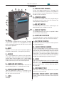
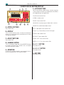
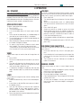
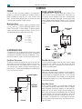
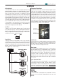
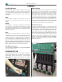
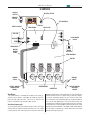
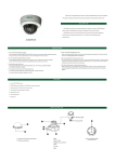
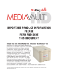
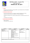
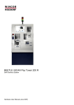
NKL AUTOBANK
D8X
SERVICE Manual
NKL is a member of FireKing Security Group
101 Security Parkway — New Albany IN 47150 USA
Ph. 800.528.9900 or 812-948-8400
www.fireking.com
®
© 2008 FireKing Security Group.
NKL , FireKing , and AuditLok are registered trademarks of FireKing Security Group.
®
®
®
®
®
Doc 801808 • Rev 11/2008
D8X Service Manual
1 INTRODUCTION
technology
Scope
AuditLok XLV is an electronics package designed to
control access to safe compartments and perform all
control and monitoring functions required by the hardware. The D8X is not equipped with a cpu. It is therefor
limited to stand-alone operation and only basic vending
and lock control features.
This manual supports NKL Autobank D8X dispensing
safes. This manual is intended to be used by authorized
service technicians only. Unauthorized service will void
the safe warranty and/or service agreement.
This manual contains abbreviated operation and
programming instructions. Complete safe operating
instructions are found in the User Manual supplied with
the safe.
D8X Safes
D8X safes hold eight columns of ten tubes each. The
manager loads tubes filled with rolls of cash or coins,
then cashiers dispenses the tubes as needed during
the course of the business day. D8X safes are equipped
with a manual drop drawer. Drops may go into a locked
interior compartment although the inner compartment
is optional. D8X uses Medeco keys for access control.
The outer door delay is fixed at 10 minutes. Vend delay
is set by DIP switches with a factory default value of 2
minutes. If equipped with an inner compartment, the
inner door lock will be a key operated lock.
This manual contains basic theory of operation, troubleshooting help, repair instructions, and electrical and
mechanical parts information.
The original version of this service manual was written
in 2001 and it covered all Autobank safes with AuditLok
XLV electronics. This updated edition covers the D8X
only. Other models now have their own service manuals. Contemporary manufacturing is assumed unless
specifically noted otherwise.
2
D8X Service Manual
2 CHASSIS
G
H
I
J
G—Manual Drop Drawer
K
Pull out, insert drop envelop, push in. The drop will fall
into the inner compartment, if present, or the bottom of
the safe if there is no inner compartment. The drawer
includes an anti-fish feature.
L
F
M
H—Drawer handle
The plastic insert handle makes it easy to grab and pull
the drawer out and it is nearly flush with the front of the
safe to prevent accidental injury.
E
D
I—ACO Key switch
C
This Medeco electrical key switch is used to bypass the
outer door delay for armored car service.
N
B
j—mGr key switch
This Medeco electrical key switch is required for door
access and the unload feature.
A
K—AuditLok XLV keypad
The keypad features a touch-membrane surface for
protection from spills and a 20x4 fluorescent display.
O
A—Door
L—ON-STBY key switch
The outer door is made of 3/8 inch A-36 steel. The door
is laser cut for a perfect fit. It is equipped with a high
quality, low profile boltwork for the best security and
most efficient operation.
This electrical key switch must be ON in order to perform
any keypad operations.
M—chassis serial number
B—Body
The serial number begins with SP to indicate manufacture by the FireKing Security Products plant location
(early D8 safe serial numbers began with NK to indicate
NKL brand). The first four numbers indicate year of
manufacture. The next three numbers indicate week of
manufacture. The last three numbers indicate sequential
number of unit built during that week of that year.
The body is 1/4 inch steel. Inner compartment optional.
All electrical connections via rear panel (not shown).
C—Handle
The “T” style handle on this safe turns 90° right (clockwise) to open. When the handle is turned, its bolts retract
and lock open. When the door shuts, a spring loaded
detent mechanism fires the bolts to lock the door and the
handle automatically returns to the locked position.
N—Hinge
Safes have two welded hinges on which the door swings
open, up to 180°. Do not attempt to clean hinges.
Commercial cleaning chemicals will cause the hinge
lubricant to break down, making it difficult to open or
close the door.
D—Tubelock Key switch
This Medeco key switch is used to open and close the
tube lock blocking bar. It is used to prevent fishing.
®
O—Dispensary Tray
E—load Column Openings
When tubes are vended, they drop into this tray area
where they may be retrieved.
Tubes are loaded here. Column 1 is to the left as you
look at the front of the safe; column 8 is to the right as
you look at the front of the safe.
External Power Supply (Not Shown)
A power supply transformer connects to the rear panel
of the safe.
f—label
Safe logo.
3
D8X Service Manual
3 AUDITLOK XLV KEYPAD/DISPLAY
A
B
F—Action Buttons
D
C
Not all action buttons apply to every safe, but any given
system could use almost any combination of action buttons depending on the application.
LOAD: Not used on D8X.
VEND: Used to vend.
DROP: Not used on D8X.
E
F
G
H
UNLOAD: Used to empty all tubes from a column.
I
DOORS: Used for outer door access.
A—Scroll Buttons
Not used on D8X..
BUY CHANGE: Not used on D8X.
B—Display
display: Check delays or error messages.
This is an 80 character (4 rows, 20 columns) fluorescent
display. It can easily be read at some distance in almost
any lighting condition.
PGRM: Not used on D8X.
C—Select Buttons
DROP SET: Not used on D8X.
REPORT: Not used on D8X.
Not used on D8X..
INSTA 1, 2, 3, 4: Not used on D8X.
D—Numeric Keypad
G—Esc Button
This is a standard number pad. Use the ENTER button
to accept an entered value. Use the cancel button
start over entering a number.
Not used on D8X..
H—HELP Button
E—mounting
Not used on D8X..
For security the display module is mounted to the chassis
or EPR using two Torx (T-25) security screws.
I—Key Port
Not used on D8X..
4
D8X Service Manual
4 operation
on / standby
Unload
Place the ON-STANDBY key switch in the ON position
before using any operator features. In the ON position,
this key switch allows vending, unloading, and opening
the door. Place the ON-STBY switch in the STBY position
to disable operator features. Standby prevents unauthorized use of vend, unload, and door features.
If an error is made when loading (tube inserted in wrong
column) or for whatever reason you need to remove all
tubes from a column (or columns) follow these steps:
1. Press UNLOAD.
2. Turn the Manager Key to initiate the 5 minute unload
delay.
3. When the unload delay ends, an audible beep
will sound and the unload access time will count
down.
4. Press UNLOAD again.
5. Select the column to unload, or press the arrow
select button next to ALL to unload all columns.
The tubes will begin being ejected immediately. To
prevent a tube jam, remove each tube as soon as
it falls into the dispensing tray.
6. If you need to unload a second column, repeat Steps
5 and 6.
7. To exit the Unload procedure, press UNLOAD, then
press ESC.
Open outer Door
To open a door follow these steps:
1. Press DOORS.
2. Turn the Manager Key.
3. A 10 minute door delay* will count up on the display.
4. At the end of the door delay, an audible beep will
sound to let you know the delay is complete.
5. Turn the Manager Key to unlock the door before the
access period ends.
6. When the display indicates OPEN DOOR NOW, turn
the handle and open the door.
7. As soon as your business inside the safe is done,
shut the door. The safe will automatically lock.
*To override the 10 minute door delay, turn the Armor
Car Override (ACO) Key and skip to Step 6.
Checking Tube Quantities
Use your D8 Dipstick to check how many tubes are in
each column:
1. Place the tube lock key switch in the open position.
2. Insert the dipstick into the opening at the top of the
column you wish to check until the stick is stopped
by a tube.
3. The number on the stick indicates the number of
tubes in the column.
Vend
Follow these steps to vend a tube of change from the
safe:
1. Press VEND.
2. Press the number button for the column you want to
vend.
3. The tube will drop into the dispensing tray at the
bottom of the door. Take your change from the tube
and set the tube aside for re-use.
4. A vend delay will begin immediately after the tube
drops. No more tubes may vend until the vend delay
ends.
Manual Drops
Follow these steps to make a manual drop into the
safe:
1. Prepare your money and deposit slip by inserting
them into an NKL drop envelope.
2. Pull out the safe’s drop drawer.
3. Place the drop envelope in the drawer.
4. Close the drop drawer. The envelope will fall into the
interior of the safe.
5. To verify the envelope is secure, pull the drawer
back out to check that the envelope is no longer in
the drawer.
Load
To put tubes of change into the safe for vending, follow
these steps:
1. Place the tube lock key switch in the unlocked position.
2. Insert tubes as desired. Be sure to put each tube in
the proper column.
3. Use your D8 Dipstick to measure the number of
tubes in order to verify tube quantities. When a
column contains 10 tubes, no additional tubes can
be loaded in that column.
4. Return the tube lock to the locked position to prevent
unauthorized loading.
5
D8X Service Manual
5 service
Power
door Locking System
One of the most common problems with electronic
products is partial or complete loss of power. External
power supplies are used with NKL safes so that a safe
does not need to be drilled open to service the more
common types of power supply failures.
A slide-bolt lock is used on outer doors today. Early
safes used a LaGard swing-bolt lock. Either lock has
an internal sensor to detect if the lock is locked (bolts
extended) or not (bolts retracted). An external plunger
sensor detects door condition (open or shut). The lock
is connected to a lock board via crossover RJ45/RJ45
cable.
Main Power Supply
The three-level main power supply transformer output
(±12 VDC and +5 VDC) may easily be checked with a multimeter. The pin-out is shown below. To prevent power
supply failure due to surges or spikes, always use an
uninterruptible power supply with your safe.
1
3
4
2
5
VEND
BOARD
J7
1 = COM
2 = COM
3 = +5 VDC
4 = –12 VDC
5 = +12 VDC
J1
J2
LOCK BOARD
J4
SENSOR
J3
J5
SENSOR
CABLE
Electronics can
The electronics can inside the D8X contains only cable
harnesses for routing power to the display and data to
and between the display and main vend board. Can replacement requires access to the inner compartment.
LOCK
LOCK
CABLE
Door Will Not Lock
Can Repair / Replacement
In this situation the bolts throw normally when the door
closes but the handle can still be turned and door
opened at any time. The problem may be the lock or
the lock controller board.
To replace, disconnect power from the rear of the safe,
disconnect the vend and display cables from the can,
then remove the hex nuts holding the can in place. The
can should easily slide out. Reverse these steps to replace the can. The only replaceable part inside the D8X
can is the internal harness.
Test for Stuck Lock Solenoid
Open the safe door. Press the detent to throw the bolts.
Disconnect the lock cable at the lock. If the handle can
still be turned the solenoid inside lock is stuck and the
lock must be replaced. If the handle can no longer be
turned the lock board is the most likely problem and it
should be replaced.
TRANSFORMER
SAFE POWER
Door Won’t Unlock
INTERNAL
HARNESS
DISPLAY
LOCK BOARD
CABLE
In this situation the door is assumed to be closed and
the handle cannot be turned when the lock is supposedly energized (everything appears to work normally
otherwise). Any of several things may be wrong: lock,
lock cable, lock board to vend board cable, lock board
or vend board. The most likely problem is pressure
against the inside of the door making it difficult to turn
the handle. This problem can usually be overcome by
pushing against the outside of the safe door while turning the handle.
VEND
D8X CAN
6
D8X Service Manual
5 service
Drill and Repair
If the door is locked shut and cannot be opened using
door procedures the door must be drilled open. Contact
NKL Technical Service for assistance with drilling instructions. In most cases the cause is a failed lock. Drilling
the door open will destroy the lock. After replacing the
lock, test door operation with the door open (press and
hold the door sensor to silence the alarm). If the new lock
does not solve the problem test the MGR and ACO key
switches. Next check the key harness cable connection
to the vend board and continuity of each of those wires.
If the problem is not found test the new lock to ensure
the new part is functioning properly. If the problem is
still not found replace the lock board.
Continuous Door Alarm
A continuous alarm tone sounds if the lock or door sensor
indicates that the door is open more than five minutes
or if either sensor detects the door come open without a
signal to energize the lock. If the door is shut and locked
and the door alarm is sounding, the most likely cause is
the door (plunger) sensor. If the a sensor fails the safe will
continue to alarm until repaired (or power is removed).
The door will still operate normally with a failed sensor
although the normal beeps will not be heard due to the
alarm condition. When the plunger sensor breaks it is
usually easy to see by visual inspection.
Lock Test
Connect a 9 VDC battery between pins 5 and 8 of the
RJ45 port on the lock. The lock solenoid should energize and the slide-bolt should freely slide into the lock
body (swing-bolt should rotate into body). If not the lock
solenoid has failed – replace the lock.
PIN 1
PIN 8
Detent
Sensor
LOCK
Key Switches
The key switches are mounted in such a way that they
are difficult to access directly with a meter. The easiest
way to check continuity is to disconnect the key harness
from the vend board (J6) and measure from common
(green) at the wire harness plug. Key switches are normally open. Key switch wiring:
Lock Sensor
Sensor continuity may be tested by measuring continuity
between pins 3 and 2 (normally open) or between pins
3 and 4 (normally closed) at the RJ45 jack on the lock.
If the lock sensor fails replace the lock.
Door Sensor
A simple spring loaded plunger sensor is used to detect
physical door status. The plunger switch is normally
open. When the plunger switch is pressed (door shut),
the plunger switch closes. To replace the sensor remove the vend assembly, remove the sensor screws,
disconnect the sensor wires from the cable harness
back to the lock board. Reverse these steps to replace
the sensor.
VEND BOARD J6
ON-STBY KEY SWITCH
YELLOW
MGR KEY SWITCH
Lock Crossover Cable
The cable from lock to lock board is a reverse wired
(crossover) RJ45/RJ45 cable. The lock cable is always
connected to J3 on the lock board. NKL uses a black
crossover cable for easy identification. Connecting the
lock via a one-to-one (straight-through) cable to the J3
port on the lock board will definitely cause lock board
failure.
ORANGE
ACO KEY SWITCH
GRAY
Lock Board
The lock board is mounted on the outer door. The lock
board may be replaced independently from the vend
board.
GREEN
7
D8X Service Manual
5 service
Vending Operation
Outer Door Mechanical
Tubes are loaded through the openings near the top
of the door. Fishing is prevented by a key operated
tube blocking bar. Tubes are held in columns according to their value. The assembly has four DC motors.
Each motor serves two columns. Optic sensors on the
motor board detect motor travel. At rest the motor sensors should indicate the rotor cap is centered between
columns. Tubes are vended out to the dispensing tray
at the bottom of the door. As tubes dispense they pass
through and break an optic beam. This beam allows the
safe to count tubes during an unload operation.
Door blockage, loose or broken linkage, or some other
mechanical problem can prevent a door from opening
or shutting correctly. Always perform a complete visual
inspection of all mechanical parts when servicing a
safe door.
Hinges
The outer door is right-swing (hinges to the right as
you look at the safe). Do not use chemical cleaners on
hinges.
Boltwork
The boltwork is a relatively simple 3-point low-profile
style. The lock is mounted on a bracket at a right angle
with respect to the door surface. An “F” guide is mounted
to the lock bracket to keep the main vertical bolt linkage
aligned and secure.
Vend Assembly Plastics
The vend assembly body parts are constructed using
patented plastics technology for tight tolerances and
long sturdy life. If the plastics break the entire assembly
can be replaced. To remove the plastics disconnect the
RJ45 cables from the can and lock board, disconnect
the key harness, disconnect the tube lock yoke, remove
the four shoulder bolts holding the assembly to the safe
door, pull the assembly off the door and set on a static
free mat. All electrical components can be stripped off
the old assembly and mounted on the new assembly
before reinstallation.
Detent
The boltwork assembly includes an automatic detent.
The detent rod runs across the door between the interior door surface and the vend assembly. To adjust the
detent, loosen the hex nut behind the brass end piece,
turn the end piece as needed, then tighten the hex nut
in place. The detent should reliably catch and hold the
bolts retracted when opening the door and should throw
the bolts automatically when the exterior surface of the
door is about flush with the chassis front surface.
Inner Door (if applicable)
The inner door is equipped with a simple key operated
lock and no door sensor.
Dispensing System
The dispensing system consists of the plastic vend assembly, tube blocking bar and key lock, vend board,
motor board, motors, output sensors, and associated
cables. D8X units hold up to 80 tubes in the vending
mechanism.
8
D8X Service Manual
5 service
ACO KEY
SWITCH
ON-STBY SWITCH
MGR KEY
SWITCH
KEY HARNESS
DISPLAY CABLE
DISPLAY
VEND BOARD
D8X IC CHIP
J5
D8X CAN
J4
DISPLAY
J3
VEND
J2
J6
J1
J7
LOCK BOARD
CABLE
J1
LOCK
BOARD
VEND CABLE
MOTOR
RIBBON
CABLE
VEND ASSEMBLY
MOTOR
SENSOR
CABLE
OUTPUT SENSOR
TRANSMITTER
BOARD
SENSOR
CABLE
MOTOR BOARD
ROTOR CAP
Vend Board
OUTPUT SENSOR
RECEIVER
BOARD
between the display and vend board. A short RJ45/RJ45
cable connects from J7 (open side) to the lock board.
A five-pin connector plugs into J6. The four wires from
this connector are routed through the armored cable to
the can for their protection. From there those wires are
routed to the inside of the front panel to the key switches
mounted there. A broad ribbon cable connects the vend
board to the motor board. The ribbon cable sends power
to the motors and receives sensor data from the motor
board and output sensors.
The vend board is mounted to the top of the vend assembly. Input sensors, although not used on the D8X,
face into the tube channels. The main IC chip on the
D8X is marked to indicate the code version.
Vend Board Connectivity
An armored RJ45/RJ45 cable connects from J2 (hinge
side) to the can against the back interior wall. This cable
carries power from the external transformer and data
9
D8X Service Manual
5 service
Motor System
DIP Switch Settings
Set Vend Delay using segments 4 to 8 as shown in
the chart below. Two minutes is the factory default. To
disable the unload delay for test purposes set switch
segment 1 to ON. Be sure to reset Segment 1 to OFF
when testing is complete. To allow the armor car key to
be used without the manager key, set switch segment
2 to ON. Segment 3 is not used. Any time a segment
of this switch is moved power must be cycled for the
change to take effect.
Delay
8
0 Min OFF
2 Min ON
4 Min OFF
6 Min ON
8 Min OFF
10 Min ON
12 Min OFF
14 Min ON
16 Min OFF
18 Min ON
20 Min OFF
22 Min ON
24 Min OFF
26 Min ON
28 Min OFF
30 Min ON
32 Min OFF
34 Min ON
36 Min OFF
38 Min ON
40 Min OFF
42 Min ON
44 Min OFF
46 Min ON
48 Min OFF
50 Min ON
52 Min OFF
54 Min ON
56 Min OFF
58 Min ON
60 Min OFF
62 Min ON
7
OFF
OFF
ON
ON
OFF
OFF
ON
ON
OFF
OFF
ON
ON
OFF
OFF
ON
ON
OFF
OFF
ON
ON
OFF
OFF
ON
ON
OFF
OFF
ON
ON
OFF
OFF
ON
ON
6
OFF
OFF
OFF
OFF
ON
ON
ON
ON
OFF
OFF
OFF
OFF
ON
ON
ON
ON
OFF
OFF
OFF
OFF
ON
ON
ON
ON
OFF
OFF
OFF
OFF
ON
ON
ON
ON
5
OFF
OFF
OFF
OFF
OFF
OFF
OFF
OFF
ON
ON
ON
ON
ON
ON
ON
ON
OFF
OFF
OFF
OFF
OFF
OFF
OFF
OFF
ON
ON
ON
ON
ON
ON
ON
ON
Four DC motors are connected to the motor board. Each
motor controls vending from two columns through a gear
system to a rotor cup. To vend, the motor turns the rotor
in the appropriate direction until a tube drops into the
rotor cup. The motor then turns the rotor back to center
alignment and the tube drops out. The example below
illustrates how one motor-operated rotor cup vends one
tube from a pair of columns.
CENTER
ALIGNMENT
4
OFF
OFF
OFF
OFF
OFF
OFF
OFF
OFF
OFF
OFF
OFF
OFF
OFF
OFF
OFF
OFF
ON
ON
ON
ON
ON
ON
ON
ON
ON
ON
ON
ON
ON
ON
ON
ON
ROTOR MAXIMUM
ROTATION
RETURN
TO CENTER
Motors
The DC motors are mounted directly to the plastics assembly. The motor gear engages the cup rotor pinion.
Motor wires are routed between the motor board and
the plastics and plug into the corresponding jack on the
motor board. Motors are operated by 12 VDC and they
are polarity sensitive. For test purposes a standard 9 VDC
battery may be used to attempt to move a motor. To move
a rotor cup by hand, first remove the motor mounting
screws and loosen the motor from the rotor.
Motor Board Cup Sensors
Optic sensors on the motor board track rotor cup movement to ensure proper operation. The rotor shaft cup
extends through the motor board. A cap is installed on
the end of the rotor shaft. This cap has a small notch on
one side and a large notch on the other side. The small
ROTOR CAP
ALIGNMENT
KEY
HOME
SENSOR
Vend Board Replacement
Remove power to the safe. Disconnect J2, J7, J6, and
the ribbon cable to the motor board. Remove the screws
holding the vend board to the vend assembly. Reverse
these steps when installing the new board. Set the DIP
switches on the replacement vend board before reconnecting power.
HOME
GAP
10
ROTOR CAP
END OF
TRAVEL
GAP
END OF
TRAVEL
SENSOR
D8X Service Manual
5 service
notch is used by one sensor to detect center “home”
position and the large notch is used by the other sensor
to detect the maximum travel limit. The shaft and cap are
keyed to ensure correct alignment. The cap is pressure
fit and anchored with a Phillips head screw.
bar must be in the open position and the vend board
should be removed. A thin screwdriver or similar object
may be used to push up on the obstruction from below
the assembly. There is room in the tray area and space
between cups and column walls to do this. Slots into
the columns along the back of the vend assembly allow
you to use screw drivers or similar thin metal objects to
“walk” tubes or debris up and out of the top of the assembly. If absolutely necessary motors may loosened
from their mounts to allow cups to be turned by hand.
After clearing the tube jam power cycle the safe and
verify all motors return their home positions by visually
checking rotor cap alignments.
Output Sensors
The output sensor is made up of two small circuit boards
mounted to either side of the vend assembly such that
they hang from the bottom. One side transmits a beam
of light across the empty space beneath the assembly
and the other senses the beam. Sensors are marked
to avoid confusion as to which is which. Output sensor
wires are connected to the motor board. On the D8X an
output sensor problem is likely to go unnoticed unless
you attempt to unload tubes. During an unload, if the
sensors do not detect the beam break temporarily after
tubes discharge it will only unload two tubes regardless
of the actual number of tubes in the safe. The problem
may be beam blockage, dirt on the transmitter or receiver, physical board alignment, or a failure of one of
the sensor boards or cables.
Tube Lock / Blocking Bar
The tube blocking bar is metal plate that is designed
to prevent tube fishing. When the blocking bar is in the
locked position, the tube openings are partially blocked
leaving only enough room to insert a dip stick. The bar
is moved out of the way via linkage yoke to a mechanical Medeco key switch. If the tube lock does not move
smoothly when operating the key switch, adjust the
mechanical linkage as needed. The blocking bar can
only be replaced with the plastics assembly removed
from the safe door.
Motor Board
The motor board interfaces the motors, rotor position
sensors, and output sensors with the vend board. To
replace the motor board disconnect the output sensors,
motor wires, and the ribbon cable from the vend board.
Remove each rotor cap and note which cap came from
which rotor. Remove the anchor screws and replace the
board. After reinstalling the screws, carefully reinstall the
rotor caps. It works best if you put the same cap back
on the same rotor. Reconnect all cables.
Tube Jam
One of the most common service issues is a tube jam.
Technically, a tube jam is when rotor cup position sensors are unable detect correct motor movement. The
cause is usually a broken or vertical tube or other debris inside a column blocking normal rotor movement.
Do not attempt to put fingers in the rotor area while a
motor is moving or trying to move. Before attempting to
lift tubes up and out of the assembly the tube blocking
11
D8X Service Manual
6 electrical parts
C
I
B
E
D
A
H
G
D8X CAN
VEND BOARD
J5
J4
DISPLAY
J3
VEND
J2
J6
J1
R
J7
J1
I
F
Q
J
J2
S
LOCK BOARD
VEND ASSEMBLY K
J4
J3
J5
U
T
L
V
M
O
P
12
N
D8X Service Manual
6 electrical parts
ItemPart
A 15059020
B 15097037
C 800397
D 800316
E 15000346
F 1505A001
G 1505310X
H 15009069
I 15052505
J 15053600
K 15053000
L 15053700
M 15053300
N 15053400
O 15053200
P 16000118
Q 15003006
R 15009080
S 15054000
T 15009083
U 15017000
V 15054015
Description
XLV Keypad/Display Module
Medeco Key Switch Pair (MGR & Tube Lock Keyed Alike)
Medeco Key Switch (ACO)
Wafer Key Switch
External Power Supply Transformer
D8X Can (includes internal harness 15052510
Vend Board
Display Cable
Armored Vend/Key Cable Assembly
Vend Ribbon Cable
Vend Assembly (Includes items L - Q and 800135 plastic chassis)
Output Sensor Cable (x2)
Output Sensor Transmitter (Hinge Side)
Output Sensor Receiver (Open Side)
Motor Board
Rotor Cap (x4)
Motor (x4), (800130 Motor Gear is a separate part)
Lock Board Cable
Lock Board
Lock Cable (crossover)
Lock
Sensor (includes cable)
13
D8X Service Manual
7 door hardware Parts
A
B
D
G
F
E
H
N
I
K
L
M
C
P
Q
O
J
S
Y
T
R
Z
U
V
W
14
X
D8X Service Manual
7 door hardware Parts
ItemPart
A 800135
B HS1206
C 15097037
D 16000002
E 800224
F 600113
G 700041
H 800182
I 800175
J 800153
K 800113
L 600029
800218
M 800152
N 800112
O 700007
P 600025
Q 600027
R 600028
S
T 15017000
U 6030022
V 600048
700032
800186
800211
HN700
W 700028
X 800129
Y 800231
Z 15054015
800184
Description
Vend Plastics (See Electrical Parts Item K)
Shoulder Bolt 5/16 (x4)
Medeco Key Switch Pair (MGR & Tube Lock Keyed Alike)
Tube Blocking Bar
Washer 5/16
Tube Lock Actuator
Bolt Linkage
Screw 10-32 x 5/16 (x8)
Washer #8, 7/16 OD (x3)
Handle
Bushing 3/4, 7/16 ID, 5/8 OD
Handle Actuator
Handle Spring (not shown, attached to handle actuator)
Retaining Ring
Shoulder Bolt (x3)
Bolt (x3)
Bolt Cam (x3)
Side Bolt Actuator (x2)
Bottom Bolt Actuator
Guide Bracket
Lock
Lock Screw 1/4-20 x 1 5/16
Detent Rod Assembly
Detent Rod (included with 600048)
Detent Spring (included with 600048)
Detent Stand-off Sleeve (included with 600048)
Hex Nut 8-32 (included with 600048)
Detent Plate
Retaining Ring 3/16
Screw 5/16 x 6-32 (x2)
Sensor (includes cable)
Wave Washer 7/16 (not shown)
15
D8X Service Manual
8 manual drop drawer
D
A
B
C
E
F
ItemPart
A 600764
800064
B 701242
C 701243
D HB201
E 6201050
F HN201
Description
Drop Drawer (Since SP2003028002)
Small Drop Drawer (Before SP2003028002)
Drop Drawer Nylon Stop Stop
Drop Drawer Steel Stop Bar
Drop Drawer Backstop Carriage Bolt (x2)
Drop Drawer Backstop Washer (x2)
Drop Drawer Backstop Hex Nut (x2)
9 other parts
Part
800513
800517
06030008
800328
800254
800234
800149
800151
6101001
800338
800346
800208
800268
800372
600131
16000039
BT-1189
801082
Description
Dust Cover (latchable, since 2002)
Dust Cover Latch
Dust Cover Screw, 4-40 x 1/4 (x7)
Dust CoverScrew, 5/16-18 x 7/8 (x4)
Dust Cover (old screw on style)
Dust Cover Screw, 8-32 x 1/4 (for old style)
Hinge Pin
Hinge Ball Bearing
Inner Door Key Lock
D8X Operator’s Manual
Installation Instructions
D8 Label 1/2 x 3 7/8
Autobank Label 3.5 x 14.25
Anchor Kit
Replacement Tubes (box of 80)
Magnetic Tube Rack
Dipstick
APC Uninterruptible Power Supply
16