1
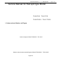
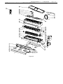
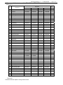
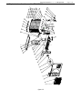
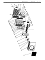
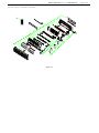
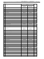
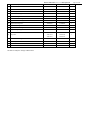
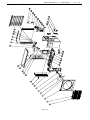
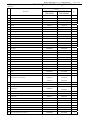
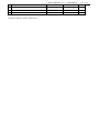
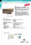
Service manual for Turbo Air Mini-split unit
TAS-09VH,TAS-12VH
TAS-09VH/O,TAS-12VH/O
TAS-18V,TAS-24V,TAS-18V/O,TAS-24V/O
TAS-18VH,TAS-24VH,TAS-18VH/O,TAS-24VH/O
Page 1 of 35
Service manual for Turbo Air Mini-split unit
Service Manual for Wall split type Model
TAS-09VH,TAS-12VH
TAS-09VH/O,TAS-12VH/O
1.1 Indoor unit and Outdoor unit Figures
Indoor unit figure of Model TAS-09VH,TAS-12VH
Outdoor unit and remote controller figures of Model TAS-09VH/O,TAS-12VH/O
Figure 2-1
Page 2 of 35
Service manual for Turbo Air Mini-split unit
Page 3 of 35
1.2 Exploded view of indoor unit TAS-09VH, TAS-12VH
18
41
17
16
15
14
19
20
13
22
12
23
11
24
10
25
9
26
8
7
27
28
6
29
30
31
32
5
4
33
3
34
2
35
1
40 39 38 37
Figure 2-2
36
Service manual for Turbo Air Mini-split unit
Page 4 of 35
1.3 Spare parts list for indoor unit for TAS-09VH and TAS-12VH:
Table form 1-1
No.
Description
Part Code
Qty
N/A
TAS-09VH
N/A
Louver A
100420003
100420003
100420087
2
Louver B
100420083
100420083
100420088
100420088
1
3
Swing Louver
100420007
100420007
100420007
100420007
12
4
Connecting rod
100420072
100420072
100420048
100420048
3
5
Outlet part
391200006
391200006
100090129
100090129
1
6
Left angle plate
100360001
100360001
100360002
100360002
1
7
Base
100060108
100060108
100060138
100060138
1
8
Cross flow fan
100010016
100010016
100010026
100010026
1
9
Fan Bearing
401000006
401000006
401000007
401000007
1
10
Evaporator assembly
972900499
972900499
972900477
972900477
1
1
TAS-12VH
100420087
1
11
Evaporator left fixed plate
029993988
029993988
109990108
109990108
1
12
Screw cover
109990023
109990023
109995908
109995908
2
13
Middle frame
391070007
391070007
391070003
391070003
1
14
Air Filter
100190127
100190127
100190139
100190139
2
15
Display box cover
100410009
100410009
100410009
100410009
1
16
Display lamp plate
337000041
337000041
337000041
337000041
1
17
Display box
100410001
100410001
100410001
100410001
1
18
Front Panel
391022026
391022026
391022049
391022049
1
19
Sponge bar
----------
-----------
------------
------------
20
Connecting Cable
-----------
-----------
------------
------------
21
Power Cord
-----------
----------
------------
22
Middle frame coverplate
100080034
100080034
100080034
100080034
1
23
Room temp. Sensor Holder
079990030
079990030
100280105
100280105
1
24
Pipe Clamp
100430025
100430025
029991901
029991901
1
-------------
25
Evaporator right fixed plate
109990109
109990109
109990109
109990109
1
26
Motor platen
100130003
100130003
100130003
100130003
1
27
Motor
320204004
320204004
320204004
320204004
1
28
Electric box cover
391100011
391100011
391100011
391100011
1
29
Electric control plate
331200083
331400083
331200083
331400083
1
30
Transformer
321620014
321620014
321620014
321620014
1
31
Terminal Board
321000022
321000022
321000022
030090241
1
32
Electric box
391100011
391100011
391090014
391090014
1
33
Screw
150010058
150010058
150010058
150010058
2
34
Wire Clip
391110057
391110057
391110018
391110018
1
35
Right angle plate
100300003
100300003
100300026
100300026
1
36
Wall-mounting frame
020100010
020100010
020100011
020100011
1
37
Step motor
320273001
320273001
320273001
320273001
1
38
Step Motor plate
391200050
391200050
100420002
100420002
1
39
Crank connecting rod
100420082
100420082
100420082
100420082
1
40
Thermal insulation pipe
099990080
099990080
099990080
099990080
1
41
Remote controller
336821050
336821049
336821050
336821049
1
PLS NOTE:
The above data are subject to change without notice.
Service manual for Turbo Air Mini-split unit
1.4 Exploded view of outdoor unit for TAS-09VH/O
figure 2-3
Page 5 of 35
Service manual for Turbo Air Mini-split unit
Page 6 of 35
1.5 Spare parts list of outdoor unit for TAS-09VH/O
Table 1-2
No
Description
Part No
Qty
N/A
TAS-09VH/O
Front Grill
020120015
020120015
1
2
Grill Clip
109990256
109990256
8
3
Front Plate
020070056
020070056
1
4
Small handle
100050021
100050021
1
5
Nut
150020009
150020009
1
6
Gasket
453000010
453000010
1
7
Axial flow fan
100030006
100030006
1
8
Motor
320224004
320224004
1
9
Motor support
020040045
020040045
1
10
PE Sponge
090020234
090020234
1
1
11
Base
313013036
313013036
1
12
Anti-vibration pad for the compressor
010011455
010011455
3
13
Compressor
303314002
303314002
1
14
Gasket
150030018
150030018
3
15
Nut
150010004
150010004
3
16
Top panel
029994517
029994517
1
17
Partition board
313030027
313030027
1
18
PU Sponge
090020027
090020027
1
19
Electric installation board
313120021
313120021
1
20
Compressor Capacitor
030010019
030010019
1
21
Capacitor Clamp
020140010
020140010
1
22
Terminal Board
030090061
030090061
1
23
Fan Capacitor
320110003
320110003
1
24
Wire Clip
321100011
321100011
1
25
PU Sponge
---
---
---
26
Rear Grill
020110002
020110002
1
27
Span Pipe
---
---
28
Span Pipe
---
---
29
3-way Pipe
070130049
070130049
1
30
Condenser
372200075
372200075
1
31
4-way Valve
973500044
1
32
Intake pipe for the condensor
960600019
960600019
360420016
360420016
360440030
360440030
1
33
Capillary Assy
971900145
971900145
1
34
Damping rubber
110030015
110030015
1
35
Filter
070190007
070190007
1
36
Right panel
313060028
313060028
1
37
Large handle
100040002
100040002
1
38
Valve installation plate
029994567
029994567
1
39
High-pressure valve
352120005
352120005
1
40
Low-pressure valve
352260005
352260005
1
41
Screw
150010043
150010043
4
42
Drainpipe for the condensor
360540049
360540049
1
Service manual for Turbo Air Mini-split unit
43
Discharge pipe
070010551
Page 7 of 35
070010005
1
44
Damping block
110020002
110020005
4
45
Suction pipe
360130131
360130131
1
46
Damping rubber
110030023
110030020
1
47
Connecting Wire
050030023
050030023
1
PLS NOTE THAT:
1. In the above table, “ ---- “ means that the related model don’t have this component.
2. The data are subject to change without notice.
Service manual for Turbo Air Mini-split unit
1.6 Exploded view of outdoor unit for TAS-12VH/O
Page 8 of 35
Service manual for Turbo Air Mini-split unit
Page 9 of 35
1.7 Spare parts list for outdoor unit for TAS-12VH/O
(Table form 1-3)
No
Description
Part No
N/A
TAS-12VH/O
Qty
1
Front Grill
100380001
100380001
1
2
Front Plate
313070024
313070024
1
3
Nut
150020031
150020031
1
4
Gasket
150030017
150030017
1
5
Axial flow fan
100030005
100030005
1
6
Motor
320224003
320224003
1
7
Motor support
313040011
313040011
1
8
Base
313011057
313011057
1
9
Compressor
303314001
303314001
1
10
Partition Board
313030028
313030028
1
11
PU Sponge
090010222
090010222
1
12
Electric installation board
020130005
020130005
1
13
Compressor Capacitor
030010019
030010019
1
14
Capacitor clamp
020140010
020140010
1
15
Fan Capacitor
320110008
320110008
1
16
Terminal Board
030090265
030090265
1
17
Wire Clip
321100008
321100008
1
18
PU Sponge
090020150
090020150
1
19
Condenser
372200071
372200071
1
20
Small handle
100050018
100050018
1
21
Rear Grill
020270001
020270001
1
22
Large handle
020280001
020280001
1
23
Handle
1
24
Intake pipe for the condensor
100050022
100050022
070040063
070040063
070040064
070040064
070030102
070030102
1
25
Capillary Assy
960800037
960800037
1
26
4-way valve Assy
----------
990085101
1
27
Damping rubber for capillary
-----------
---
28
Filter
070190034
070190034
070040063
070040063
29
Drainpipe for the condensor
070040064
070040064
070040064
070040064
360230113
360230113
1
1
30
Discharge pipe
31
Anti-vibration pad
110020008
110020008
360130127
360130127
070020013
070020013
1
1
32
Suction pipe
1
33
Anti-vibration damping rubber
110030023
110030023
1
34
Low-pressure valve
352260005
352260005
1
35
High-pressure valve
352120005
352120005
1
36
Valve installation plate
313020013
313020013
1
37
Anti-vibration pad for the compressor
010011455
010011455
3
38
Compressor power cord
345100018
345100018
1
39
Anchor bolt for the compressor
313225047
313225047
3
Service manual for Turbo Air Mini-split unit
Page 10 of 35
Pls note: The data are subject to change without notice.
1.8 PCB function manual
Function
1.Cooling
●
The indoor temperature is detected by room temperature sensor of indoor units and the room
temperature is controlled by the cyclic switch of compressor under the control of the electric control
board.
●
When power on for the first time, it is allowed to start up the compressor immediately; in order to protect
the compressor, it is required to stop compressor immediately such as transforming mode, heating mode
overheat protection and shutdown after starting up the compressor; furthermore, it is advisable to stop
the compressor according to practical situations after it has run at least for three minutes. In general, the
electric control board will not start up the compressor within three minutes at least after shutting down the
compressor.
●
Outdoor blower fan and compressor work synchronously; the indoor blower fan is running at the set wind
speed; when the automatic wind is selected, the indoor blower fan running speed is select by the
difference between room temperature and setting temperature.
●
Start up the compressor: when the room temperature is more than Ts+1 (Ts
compressor → start-up
●
Shut down the compressor: when the room temperature is less than the set temperature Ts ,
compressor → shutdown
a.
Working curve for temperature control
¡ ã
C
Set 设定温度
temperature
¡ ã
C
Room
tempature
室温
more
than
three
minutes
分以上
Compressor
开启
压缩机 Start-up
Outdoor
室外风机
开启
blower fan Start-up
Indoor blower
室内风机
fan
more
than
three
minutes
分以上
Shutdown
关闭
Shutdown
关闭
开启
Start-up
开启
Start-up
设定风速
Set wind speed
more
than
three
minutes
分以上
关闭
Shutdown
开启
Start-up
关闭
Shutdown
开启
Start-up
is the set temperature),
Service manual for Turbo Air Mini-split unit
2.Anti freeze protection function of
Page 11 of 35
evaporator (cooling or dehumidify)
●
This function is to prevent freezing on the surface of indoor evaporator.
●
When the temperature of coil pipe of the indoor units is less than or equal to 1 and the compressor has
continuous run for more than ten minutes, the compressor and outdoor blower fan shut down through the
electric control board and the indoor blower fan is running at low speed wind.
●
When the temperature of coil pipe of the indoor units is more than or equal to 7 and the compressor
has shutdown for more than three minutes, the compressor and outdoor blower fan start to run and the
indoor blower fan is running in the set mode.
Room
室温
temperature
T+1℃
¡ã
C
Set
temperature
设定温度
T℃ ¡ã
C
Temperature
室内蒸发
of coil pipe7¡ã
C
of器盘管温
indoor
0¡ã
C
evaporator
度
more
than
three
minutes
分以上
more
than
three
minutes
分以上
More than
10分以上
ten
minutes
More than
分以上
ten minutes
Compressor
压缩机
Outdoor blower
外风机
fan
Indoor
blower
室内风机
fan
Start-up
开启
Shutdown
关闭
Shutdown
关闭
Start-up
开启
低风运行
设定速度
Set speed Run at
low speed wind
Set speed
设定速度
Run 低风运行
at low speed wind
3.Heating (only applicable to dual temperature units)
●
The indoor temperature is detected by room temperature sensor of indoor units and the temperature
controlled by the cyclic switch of compressor under the control of the electric control board.
●
When power on for the first time, it is allowed to start up the compressor immediately; in order to protect
the compressor, it is required to stop compressor immediately such as transforming mode, heating mode
overheat protection and shutdown after starting up the compressor; furthermore, it is advisable to stop
the compressor according to practical situations after it has run at least for three minutes. In general, the
electric control board will not start up the compressor within three minutes at least after shutting down the
compressor.
●
In general, start up the compressor and the outdoor blower fan in the heating mode. The working mode
of four-way valve is to open the four-way valve when starting up the compressor. In the course of defrost,
the outdoor blower fan and the four-way valve are closed when the compressor starts up. In the course
of heating, the compressor is closed without power breakdown or the mode is transformed and two
minutes later, the four-way valve is closed.
Service manual for Turbo Air Mini-split unit
Page 12 of 35
●
In the heating mode, the indoor flower fan can be set as high/ medium/ low /automatic running mode by
remote control. however, the anti cool air function is prior. In the heating mode, the anti cool air control
function is to control shutdown of the indoor blower fan, lower (low speed )wind mode, setting the wind
speed by detecting the temperature of coil pipe of evaporator so as to attain the purpose of preventing
cold air from blowing. When the compressor starts up, the specific situations are shown in the following
figure. When the compressor is closed and the temperature of coil pipe of indoor evaporator decreases
and is less than 30 , the indoor blower fan is closed. When the compressor is turned on and the
temperature of coil pipe of indoor evaporator decreases and is less than 20 , the indoor blower fan is
closed. The operating lamp is light for 0.5s and close for 0.5s to indicate the anti cool air.
●
Start up the compressor: when the room temperature is less than Ts +2 (Ts
compressor → start-up
●
Shut down the compressor: when the room temperature is more than or equal to the set temperature
Ts +3 , compressor → shutdown
●
The electric heating start-up in the heating mode shall meet the following conditions:
start up the
compressor and indoor blower fan
room temperature ≤ the set temperature - 4 and room
temperature ≤23
the temperature of indoor coil pipe < 50
non defrosting mode
no sensor
failure.
●
For the waste heat emission function in the heating mode, in principle, the indoor blower fan shall be on
for one minute after the electric heating is closed. If electric heating with power breakdown in the
defrosting mode, the indoor blower fan is closed after it is running 20s. When the remote controlled is
used or emergency key is pressed to turn on and off, it is required to continue conducting the function if
the waste heat emission time is less than one minute, that is to say, the indoor blower fan is running at
the low speed wind and the air door is the position of all open and one minute later, it is closed.
is the set temperature),
Electric heating
On
Off
Room temperature
Turning on and off of electric heating and working curve of room temperature
Service manual for Turbo Air Mini-split unit
Set the wind speed
43¡ ã
C
Set the wind speed
Running
37¡ ã
Cat the
low speed wind
30¡ ã
C
20¡ ã
C
Anti cool air
Shut down the
blower fan
Running at the
low speed wind
Temperature of coil pipe
of indoor evaporator
The running state of indoor blower fan when the
compressor starts up
Page 13 of 35
Service manual for Turbo Air Mini-split unit
Working situations of compressor in the heating mode:
T+3℃¡ãC
C
Set temperature ¡ã
设定温度
T+2℃
Room
室温
temperature
Compressor
压缩机
Outdoor
blower fan
室外风机
Shutdo
wn
关闭
Start-up
开启
Shutdo
wn
关闭
Start-up
开启
Shutdown
关闭
Shutdown
关闭
开启
Start-up
Start-up
开启
Shutdown
关闭
Shutdown
关闭
Cold blast proof
防
Indoor
blower fan
室内风机
Shutdo 冷
wn 风 Breeze
running
关闭
微风运行
Set设定速度
speed
Set
speed
设定速度
Breeze running
微风运行
C
room
evaporator 43¡ã
室内蒸发器
surface
humidity
表面温度
37¡ã
C
30¡ã
C
Four-way
valve
四通阀
Shutdo
wn
关闭
2Two
分钟minutes
Start-up
开启
Shutdown
关闭
Start-up
开启
Two
minutes
2分钟
Shutdown
关闭
Page 14 of 35
Service manual for Turbo Air Mini-split unit
Page 15 of 35
4.Overheat protection of evaporator (only applicable to the heating mode)
●
This function is to prevent overheat of
●
When the temperature of coil pipe of indoor units rises to 61 , the compressor and outdoor blower fan
are closed and two minutes later, the change valve is closed. The indoor blower fan is running at the set
speed. When the temperature of indoor coil pipe is less than or equal to 50 , it is allowed to reenter the
heating mode.
●
When the temperature of coil pipe of indoor units is more than or equal to 56 , the outdoor blower fan
shuts down and it enters the overload protection; when the temperature of coil pipe of indoor units is less
than or equal to 52 , the outdoor blower fan starts up and it exit the overload protection.
Temperature of
coil pipe of
indoor evaporate
indoor evaporator.
61¡ ã
C
56¡ ã
C
52¡ ã
C
Compressor
Start-up
Outdoor blower fan
Start-up
Indoor blower fan
Shutdown
Shutdown
Start-up
Start-up
Set wind speed
5. Defrosting (only applicable to the heating mode, the intelligent defrosting is adopted)
In the heating mode, the air conditioner defrosting by outdoor electric board, defrost start-up in the heating mode shall
meet the following conditions: ① start up the compressor over seven minutes ② defrosting device of outdoor
electric board has cut ③ the time of compressor continuous working over 50 minutes. When defrosting, close the
indoor and outdoor blower fan and four-way valve. By detecting the conditions for defrosting treatment, the defrosting
time is automatically determined to exit the defrosting and re-enter the heating mode to run. The defrosting scheme is
as follows.
■
Sequence chart in defrosting mode
Service manual for Turbo Air Mini-split unit
Start
开始除霜
defrosting
Compressor
压缩机
20 seconds
秒
关闭
开启 Shutdown
Start-up
End
结束除霜
defrosting
Eight最长8分钟
minutes at longest
Start-up
开启
15 seconds
秒
Outdoor
室外风机
blower fan
开启
Start-up
Start-up
开启
Four-way
四通阀
valve
Page 16 of 35
20 seconds
秒
关闭
Shutdown
Start-up
开启
5 seconds
秒
Shutdown
关闭
Shutdown
关闭
Shutdown
关闭
Start-up
开启
Outdoor
室内风机
blower fan
Start-up
开启
Start-up
开启
Start-up
开启
开启
Start-up
Running
运行灯闪亮
lamp flashes
6.Dehumidification
Dehumidification running is to eliminate the water vapor in the air by using the cool circulating capacity, but
the dehumidification will not decrease the indoor temperature in great deal. The air conditioner automatically
repeats on and off circulation according the room temperature, which is shown in the following figure.
1.
The dehumidify procedure is run mode A one time and mode B seven times. Then repeat the procedure.
* mode A of dehumidification (each period is 12 minutes)
External blower fan of compressor: Intermittent running (run 3 minutes stop 3 minutes and run 3 minutes
stop 3 minutes.)
FMI (indoor fan): Run 3 minutes stop 3 minutes and run 3 minutes stop 2 minutes and 40
seconds, air flaps are all open.
*mode B of dehumidification(each period is 8 minutes)
External blower fan of compressor: according the difference between indoor temperature and set
temperature decide running time.
FMI (indoor fan): (according the difference between indoor temperature and set temperature decide
running time.).Air flaps are all open
Note
●
In the dehumidification mode, the indoor fan is running at the set speed.
●
When the indoor blower fan stops, the swinging leaves also stop at their current positions.
Service manual for Turbo Air Mini-split unit
Page 17 of 35
7.Ventilation working mode (only applicable to single cold machine)
In the ventilation mode, the set temperature range is 18 ~30 ( CONT when it is more than 30 and less
than 18 ). When ventilating, the compressor, outdoor blower fan, four-way valve and electric heating are all
closed and when indoor temperature is more than set temperature 2 , the indoor blower fan is running at the
set speed, when indoor temperature is less than set temperature, the indoor blower fan stop.
8.Automatic mode
Note:
●
Conditions for entering the automatic running mode are:
1.
After power-up for the first time or shutdown for one hour, start up and select the automatic operating
mode, the indoor blower fan runs 20 seconds by breeze and the working mode (cool, heating and
dehumidification) depends on Tr and if the working mode had set ,it doesn’t change with Tr.
2.
If it is not showdown in the cooling, heating or dehumidification modes, or it is not shutdown after
entering the automatic mode from the cooling, heating and dehumidification modes, start up and enter
the automatic working mode, the indoor blower fan will run 20 seconds by freeze and the working mode
depends on Tr.
3.
If it is transformed to the automatic working mode after the running time is less than 25 seconds in the
cooling, heating or dehumidification modes, it runs in the former working mode when running
automatically; if it is transformed to the automatic working mode under the circumstances it is firstly
powered up and the running time is less than 25 seconds in the cooling, heating or dehumidification
modes, the working mode depends on Tr after the indoor blower fan runs 20 seconds by breeze.
4.
If it is closed in the cooling, heating and dehumidification modes or it is closed when it is transformed
from the cooling, heating and dehumidification modes to the automatically running mode, it will restore to
the former working mode when restart-up within a hour after shutdown and the indoor blower fan will not
run 20 seconds by breeze; if the former mode is the ventilation mode, the working mode depends on Tr
after the indoor blower fan runs 20 seconds by breeze.
●
When the automatic mode is selected, the electric control board calculates the difference value between
the set temperature and room temperature, and then it is automatically switched into the cooling, heating
and dehumidification modes to keep the expected temperature. (Note: Tr represents the room
temperature and Ts represents the set temperature, the single cold machine changes from the heating
mode to the ventilation mode.)
Room temperature
TR<21
21≤TR≤26
TR>26
State
cooling
Dehumidification
Heating
the default set temperature in cooling mode is 25 ,in dehumidification and heating mode is 2 4 , actual set
temperature can add or decrease 6 base on default value..
9.Emergency key function
There is a forcible execution key on the panel of indoor units and the air conditioner can enter the cool mode
or heating mode by pressing the key when the remote controller is out of work or missing. 1. Press the key
once in the state of shutdown and enter the automatic mode. 2. Pressure the key in the running the air
conditioner is closed.
When pressing down the forcible execution key, then power up and enter the self-check program.
Service manual for Turbo Air Mini-split unit
Page 18 of 35
10.Abnormality of outdoor units
After the compressor runs five minutes, the lamp flashes 4 times per six seconds or display E4 if the
temperature of indoor coil pips is more than 25 (cool ) or less than 30 (heating) in the continuous 20
minutes. The controller will automatically shut down if the temperature of indoor coil pips is more than 25
(refrigeration ) or less than 30 (heating) in another continuous 20 minutes, that is the abnormality protection
of outdoor units and the indicator lamp keeps its former state of flashing. If the temperature of indoor coil pips
is more than 25 (cool ) or less than 30 (heating) in the second 20 minutes or the compressor shuts down,
the electric control board will store to the normal display and the time is restarted when starting up the
compressor next time.
Service manual for Turbo Air Mini-split unit
Service Manual for
TAS-18V,TAS-24V,
TAS-18V/O, TAS-24V/O,
TAS-18VH,TAS-24VH,
TAS-18VH/O,TAS-24VH/O
2.1 Summary
figure 4-1
Page 19 of 35
Service manual for Turbo Air Mini-split unit
2.2 Explosive view of indoor unit for
TAS-18V,TAS-24V TAS-18VH/O,TAS-24VH/O
figure 4-2
Page 20 of 35
Service manual for Turbo Air Mini-split unit
Page 21 of 35
2.3 Spare parts list of indoor unit for TAS-18V,TAS-24V, TAS-18VH,TAS-24VH
Table 2-1
Part No
No
Description
TAS-18V,
TAS-24V
TAS-18VH,
TAS-24VH
Qty
1
Wall-mounting frame
020100016
020100016
1
2
Base
100060127
100060127
1
3
Left angle plate
391990039
391990039
1
4
Front angle plate
391990040
391990040
1
5
Cross flow fan
100010025
100010025
1
6
Fan Bearing
401000059
401000059
1
7
Ring of Bearing
—
—
8
Room temp. Sensor Holder
—
—
9
Evaporator Assy
972900473
972900473
10
Evaporator fixed plate
090010342
090010342
1
11
Electric heater
—
—
1
12
Outlet part
391080006
391080006
1
13
Louver A
100390055
100390055
1
14
Louver B
100390056
100390056
1
15
Left Connecting rod A
10999A220
10999A220
1
16
Guide Louver Bearing A
10999A229
10999A229
3
17
Step motor left support
10999A227
10999A227
2
100390057
100390057
18
Swing louver
100390058
100390058
100390059
100390059
1
2
19
Swing louver right support
10999A226
10999A226
1
20
Swing louver middle support
10999A225
10999A225
1
21
Swing louver left support
10999A224
10999A224
1
22
Air outlet protect net
020440005
020440005
1
23
Middle frame
391070026
391070026
1
24
Screw cover
109990257
109990257
3
25
Cold Catalyst
119990011
119990011
1
26
Air filter
100190120
100190120
2
27
Display box cover
391140004
391140004
1
28
Display box
391110014
391110014
1
29
Front Panel
391022141
391022141
1
30
Right angle plate
391990038
391990038
1
31
Motor holder
100130015
100130015
1
32
Fan motor
320202004
320202004
1
33
Motor cover
100130016
100130016
1
34
Electrical box
020150086
020150086
1
35
Hook for the wire
----------
-----------
36
Wire Clamp
391110013
391110013
1
37
Electric box Panel 1
100430080
100430080
1
38
Electric box Panel 2
100430081
100430081
1
39
Display lamp plate
331800096
331800097
1
40
Room Temp. Sensor
338000009
338000009
1
41
Tube Temp. Sensor
338000009
338000009
1
Service manual for Turbo Air Mini-split unit
42
Electric control plate
331200077
331400074
-----------
-------------
030090250
030090250
---------
-------------
Page 22 of 35
1
43
Power cord
44
Terminal Board
45
Connecting cable
46
Thermal insulation pipe
099990080
099990080
1
47
Left Connecting rod B
391200037
391200037
1
48
Left middle Connecting rod
391200033
391200033
1
49
Right middle Connecting rod
391200034
391200034
1
50
Right Connecting rod B
391200038
391200038
1
51
Right Connecting rod A
391200036
391200036
1
52
Right small Connecting rod
391200043
391200043
1
53
Step motor right support
3
391200045
391200045
320273013
320273013
320273014
320273014
1
1
54
Step motor
320273015
320273015
55
Guide Louver Bearing B
391200030
391200030
1
56
Wire Clip
391110015
391110015
1
57
Water-resistant board
100120008
100120008
1
58
Remote controller
336821047
336821046
1
The data are subject to change without notice.
Service manual for Turbo Air Mini-split unit
2.4 Explosive view of outdoor unit for
TAS-18V/O,TAS-24V/O, TAS-18V/O,TAS-24V/O
figure 4-4
Page 23 of 35
Service manual for Turbo Air Mini-split unit
Page 24 of 35
2.5 Spare parts list of outdoor unit TAS-18V/O,TAS-24V/O, TAS-18V/O,TAS-24V/O
Table 2-2
Part No
No
Description
TAS-18V/O,
TAS-24V/O
TAS-18VH/O,
TAS-24VH/O
Qty
1
Front Grill
020120001
020120001
1
2
Grill Clip
109990256
109990256
8
3
Front Plate
020070036
020070036
1
4
Nut
150020031
150020031
1
5
Gasket
150030217
150030217
1
6
Axial flow fan
100030008
100030008
1
7
Motor
030020236
030020236
1
8
Motor support
020040013
020040013
1
9
Small handle
100050018
100050018
1
10
Left panel
313050001
313050001
1
11
Cpacitor clamp
313130012
313130012
1
12
Partition board
020030017
020030017
1
13
PU Sponge
090020203
090020203
1
14
Compressor Capacitor
030010066
030010066
1
15
Top panel
020080032
020080032
1
16
Electric installation board
020130035
020130035
1
17
Fan Capacitor
030010034
030010034
1
18
PU Sponge
090020150
090020150
1
19
Condenser
372100090
372100090
1
20
Terminal Board
030090265
030090265
1
21
Wire Clip
321100004
321100004
1
22
Rear Grill
020110003
020110003
1
23
Damping rubber for capillary tube
110030017
110030017
1
24
Capillary Assy
960800026
960800026
1
25
Filter
070190007
070190007
1
26
Drainpipe for the condensor
—
—
070030191
070030191
070030023
070030023
070030021
070030021
—
990088813
1
070010517
1
27
Intake pipe for the condensor
1
28
4-way valve Assy
29
Discharge pipe
070010419
30
Suction pipe
070020468
31
Anti-vibration pad
110020016
110020016
1
32
Anti-vibration damping rubber
110030023
110030023
1
33
Right panel
020060011
020060011
1
34
Large handle
100040004
100040004
1
35
Valve installation plate
020020007
020020007
1
36
Low-pressure valve
060020025
060020108
1
37
High-pressure valve
060020022
060020102
1
38
Maintenance plate
020090001
020090001
1
39
Compressor power cord
050040058
050040058
1
40
Anti-vibration pad for the compressor
305146005
305146005
3
070020467
070020468
1
Service manual for Turbo Air Mini-split unit
41
Compressor
Page 25 of 35
302115007
302115007
1
42
Nut
150020031
150020031
1
43
Gasket
150030017
150030017
1
44
Base
313011072
313011072
1
The data are subject to change without notice.
Service manual for Turbo Air Mini-split unit
Page 26 of 35
2.6 PCB function manual
Function
1.Cooling
●
The indoor temperature is detected by room temperature sensor of indoor units and the temperature controlled by
the cyclic switch of compressor under the control of the electric control board.
●
When power on for the first time, it is allowed to start up the compressor immediately; in order to protect the
compressor, it is required to stop compressor immediately such as transforming mode, heating mode overheat
protection and shutdown after starting up the compressor; furthermore, it is advisable to stop the compressor
according to practical situations after it has run at least for three minutes. In general, the electric control board will
not start up the compressor within three minutes at least after shutting down the compressor.
●
Outdoor blower fan and compressor work synchronously; the indoor blower fan is running at the set wind speed;
when the automatic wind is selected, the indoor blower fan works in the state of high-speed wind.
●
Start up the compressor: when the room temperature is more than Ts℃(Ts℃ is the set temperature), compressor
→ start-up
●
Shut down the compressor: when the room temperature is equal to or less than the set temperature Ts℃-2℃,
compressor → shutdown
a.
Working curve for temperature control
¡ã
C
Set temperature
设定温度
¡ã
C
Room
tempature
室温
more
than
three
minutes
分以上
Compressor
开启
压缩机 Start-up
Outdoor
室外风机
开启
blower fan Start-up
more
than
three分以上
minutes
Shutdown
关闭
Shutdown
关闭
Indoor blower
室内风机
fan
开启
Start-up
开启
Start-up
more
than
three
minutes
分以上
关闭
Shutdown
开启
Start-up
关闭
Shutdown
开启
Start-up
Set
wind speed
设定风速
2.Anti freeze protection function of
evaporator (cooling or dehumidify)
●
This function is to prevent freezing on the surface of indoor evaporator.
●
When the temperature of coil pipe of the indoor units is less than or equal to 0℃ and the compressor has
continuous run for more than ten minutes, the compressor and outdoor blower fan shut down through the electric
control board and the indoor blower fan is running at low speed wind.
●
When the temperature of coil pipe of the indoor units is more than or equal to 7℃ and the compressor has
shutdown for more than three minutes, the compressor and outdoor blower fan start to run and the indoor blower
fan is running in the set mode.
Service manual for Turbo Air Mini-split unit
Page 27 of 35
Room
室温
temperature
¡ã
C
Set
temperature
设定温度
¡ã
C
Temperature
室内蒸发
of coil
pipe of
C
indoor
器盘管温7¡ã
0¡ã
C
0℃
evaporator
度
more
than
three
minutes
分以上
more
than
three
minutes
分以上
More than
10分以上
ten
minutes
More than
分以上
ten minutes
Compressor
压缩机
Outdoor blower
外风机
fan
Indoor
blower
室内风机
fan
Start-up
开启
Shutdown
关闭
Shutdown
关闭
Start-up
开启
低风运行
Set speed Run at
low speed wind
设定速度
Set speed
设定速度
Run 低风运行
at low speed wind
3.Heating (only applicable to dual temperature units)
●
The indoor temperature is detected by room temperature sensor of indoor units and the temperature controlled by
the cyclic switch of compressor under the control of the electric control panel.
●
When power on for the first time, it is allowed to start up the compressor immediately; in order to protect the
compressor, it is required to stop compressor immediately such as transforming mode, heating mode overheat
protection and shutdown after starting up the compressor; furthermore, it is advisable to stop the compressor
according to practical situations after it has run at least for three minutes. In general, the electric control board will
not start up the compressor within three minutes at least after shutting down the compressor.
●
In general, start up the compressor and the outdoor blower fan in the heating mode. The working mode of
four-way valve is to open the four-way valve when starting up the compressor. In the course of frost melting, the
outdoor blower fan and the four-way valve are closed when the compressor starts up. In the course of heating, the
blower fan is closed without power breakdown or the mode is transformed and two minutes later, the four-way
valve is closed.
●
In the heating mode, the indoor flower fan can be set as high/ medium/ low /automatic running mode by remote
control. however, the anti-cool air function is prior. In the heating mode, the anti-cool air function is to control
shutdown of the indoor blower fan, breeze (low speed wind) mode, setting the wind speed by detecting the
temperature of coil pipe of evaporator so as to attain the purpose of preventing cold blast from blowing. When the
compressor starts up, the specific situations are shown in the following figure. When the compressor is closed and
the temperature of coil pipe of indoor evaporator decreases and is less than 30℃, the indoor blower fan is closed.
When the compressor is turned on and the temperature of coil pipe of indoor evaporator decreases and is less than
30℃, the indoor blower fan is closed. The operating lamp is light for 0.5s and close for 0.5s to indicate the cold
blast proof.
●
Start up the compressor: when the room temperature is less than Ts℃(Ts℃ is the set temperature), compressor
→ start-up
Service manual for Turbo Air Mini-split unit
Page 28 of 35
●
Shut down the compressor: when the room temperature is more than or equal to the set temperature Ts℃+2℃,
compressor → shutdown
●
The electric heating start-up in the heating mode shall meet the following conditions: ① start up the compressor
and indoor blower fan ② room temperature ≤ the set temperature -3℃ ③ the temperature of indoor coil
pipe < 50℃ ④ non defrosting mode ⑤ no sensor failure.
●
For the waste heat emission function in the heating mode, in principle, the indoor blower fan shall be on for one
minute after the electric heating is closed. If electric heating with power breakdown in the defrosting mode, the
indoor blower fan is closed after it is running 20s. When the remote controlled is used or emergency key is pressed
to turn on and off, it is required to continue conducting the function if the waste heat emission time is less than one
minute, that is to say, the indoor blower fan is running at the low speed wind and the air door is the position of all
open and one minute later, it is closed.
Electric heating
On
Off
Room temperature
Turning on and off of electric heating and working curve of room temperature
high speed wind
58¡ ã
C
high speed wind
50¡ ã
C
43¡ ã
C
set speed wind
set speed wind
37¡ ã
C
low speed wind
low speed wind
30¡ ã
C
anti-cool air
indoor motor stop
temperature of coil pipe
of indoor evaporator
the running state of indoor blower fan
when the compressor starts up
Service manual for Turbo Air Mini-split unit
Page 29 of 35
Working situations of compressor in the heating mode:
2
+
T
T
stop
stop
stop
stop
stop
stop
anti-cool
air
stop
lower speed
set speed
lower speed
set speed
43¡ ã
C
37¡ ã
C
30¡ ã
C
two minutes
stop
stop
two minutes
stop
4.Overheat protection of evaporator (only applicable to the heating mode)
●
This function is to prevent overheat of indoor evaporator.
●
When the temperature of coil pipe of indoor units rises to 65℃, the compressor and outdoor blower fan are closed
and two minutes later, the change valve is closed. The indoor blower fan is running at the set speed. When the
temperature of indoor coil pipe is less than or equal to 50℃, it is allowed to reenter the heating mode.
●
When the temperature of coil pipe of indoor units is more than or equal to 56℃, the outdoor blower fan shuts
down and it enters the overload protection; when the temperature of coil pipe of indoor units is less than or equal
to 52℃, the outdoor blower fan starts up and it exit the overload protection.
Service manual for Turbo Air Mini-split unit
Page 30 of 35
65¡ ã
C
56¡ ã
C
52¡ ã
C
50¡ ã
C
5.Defrosting (only applicable to the heating mode, the intelligent defrosting is adopted)
In the heating mode, the air conditioner defrosting by outdoor electric board, defrost start-up in the heating mode shall
meet the following conditions: ① start up the compressor over seven minutes ② defrosting device of outdoor
electric board has cut ③ the time of compressor continuous working over 50 minutes. When defrosting, close the
indoor and outdoor blower fan and four-way valve. By detecting the conditions for defrosting treatment, the defrosting
time is automatically determined to exit the defrosting and re-enter the heating mode to run. The defrosting scheme is
as follows.
■
Sequence chart in defrosting mode
Start
开始除霜
defrosting
Compressor
压缩机
20 seconds
秒
关闭
Start-up
开启 Shutdown
End
结束除霜
defrosting
Eight最长8分钟
minutes at longest
Start-up
开启
15 seconds
秒
Outdoor
室外风机
blower fan
Four-way
四通阀
valve
开启
Start-up
Start-up
开启
Shutdown
关闭
Shutdown
关闭
Start-up
开启
6.Dehumidification
Start-up
开启
5 seconds
秒
Shutdown
关闭
Outdoor
室内风机
blower fan
Running
运行灯闪亮
lamp flashes
20 seconds
秒
关闭
Shutdown
开启
Start-up
开启
Start-up
Start-up
开启
Start-up
开启
Service manual for Turbo Air Mini-split unit
Page 31 of 35
Dehumidification running is to eliminate the water vapor in the air by using the cool circulating capacity, but the
dehumidification will not decrease the indoor temperature in great deal. The air conditioner automatically repeats on
and off circulation according the room temperature, which is shown in the following figure.
2.
The set temperature is 24oC.
Room temperature
* Range of dehumidification A
External blower fan of compressor: Intermittent running (run 8 minutes and stop 4 minutes
Set temperature T℃
FMI (indoor fan): Run 8 minutes and 10 seconds, stop 3 minutes and 50seconds.
T-2℃
* Range of dehumidification B
External blower fan of compressor: intermittent running (open 4 minute and close 4 minute
FMI (indoor fan): (Run 4 minutes and 10 seconds, stop 3 minutes and 50seconds).
Note
●
In the dehumidification mode, the indoor fan is running at the low wind speed.
●
When the indoor blower fan stops, the swinging leaves also stop at their current positions.
7.Ventilation working mode (only applicable to single cold machine)
In the ventilation mode, the set temperature range is 16℃~31℃. When ventilating, the compressor, outdoor blower fan,
four-way valve and electric heating are all closed : when the room temperature is less than Ts-2℃(Ts℃ is the set
temperature), close indoor blower fan, when the room temperature is more than or equal to the set temperature Ts
℃,start running indoor blower fan.
8.Automatic mode
●
Conditions for entering the automatic running mode are:
5.
After power-up for the first time or shutdown for one hour, start up and select the automatic operating mode, the
indoor blower fan runs 20 seconds by breeze and the working mode (cool, heating and dehumidification) depends
on Tr and if the working mode had set ,it doesn’t change with Tr.
6.
If it is not showdown in the cooling, heating or dehumidification modes, or it is not shutdown after entering the
automatic mode from the cooling, heating and dehumidification modes, start up and enter the automatic working
mode, the indoor blower fan will run 20 seconds by freeze and the working mode depends on Tr.
7.
If it is transformed to the automatic working mode after the running time is more than 25 seconds in the cool,
heating or dehumidification modes, it runs in the former working mode when running automatically; if it is
transformed to the automatic working mode under the circumstances it is firstly powered up and the running time
is less than 25 seconds in the cool, heating or dehumidification modes, the working mode depends on Tr after the
indoor blower fan runs 20 seconds by breeze.
8.
If it is closed in the cool, heating and dehumidification modes or it is closed when it is transformed from the cool,
heating and dehumidification modes to the automatically running mode, it will restore to the former working
Service manual for Turbo Air Mini-split unit
Page 32 of 35
mode when restart-up within a hour after shutdown and the indoor blower fan will not run 20 seconds by breeze;
if the former mode is the ventilation mode, the working mode depends on Tr after the indoor blower fan runs 20
seconds by breeze.
●
When the automatic mode is selected, the electric control board automatically switched into the cool, heating and
dehumidification modes to keep the expected temperature by the room temperature. (Note: Tr represents the room
temperature and Ts represents the set temperature, the single cold machine changes from the heating mode to the
ventilation mode.)
Room temperature
Ts>26
21≤TR≤26
TR<21
State
cooling
Dehumidification
Heating
9.Time start-up and shutdown function
When the time start-up and shutdown are used, the clock of remote controller shall be corresponding to the current
clock and the timing times is less than or equal to 24 hours; if the time start-up is set in the state of start-up, the air
conditioner shuts down immediately and if the time shutdown is set in the state of shutdown, the air conditioner starts
up immediately; the minimum measure unit of timing time is ten minutes; when the time is set and it is stable and
displayed after flashing one minute. It is feasible to set the time start-up and time shutdown at the same time; the air
conditioner will work by the earlier timing time; the combination time in the timing method is the same time, the air
conditioner runs and it is closed when reaching its timing time.
10.Emergency key function
There is a forcible execution key on the panel of indoor units and the air conditioner can enter the cool mode or heating
mode by pressing the key when the remote controller is out of work or missing. 1. Press the key once in the state of
shutdown and enter the cool mode. 2. Press the key in the running, non-heating mode and enter the heating mode. 3.
Pressure the key in the running and heating mode and the air conditioner is closed.
When pressing down the forcible execution key, then power up and enter the self-check program; the display
lamps ,compressor ,indoor fan, four-way valve, outdoor fan, electric heating, buzzer, step motor will run sequence.
11.Power failure memory function
I.
Data store
1. When receiving correct remote control code in the starting or waiting state, effective remote control code,
data check and 3s time delay will be written in the specified cell in E2PROM.
2. When start-up or shutdown by the emergency key or the state of air conditioning is set by pressing the key,
the operational result of pressing the key will transformed to the control code and together with 3s time delay
is written in the specified cell in E2PROM.
3. When it is set as the time start-up function, immediate start-up is selected if power-up after power failure.
When it is set as the time shutdown function, immediate shutdown is selected if power-up after power failure.
4. If the key locking function exists before power failure, the key locking function is cancelled after power up.
II.
E2PROM data reading and processing
1. Immediately read data (control code) in E2PROM when powering up and it is discriminated whether there is
E2PROM chip or not according the state of ASK signal of reading operation; if no chip, there is no need to
execute E2PROM reading and writing operations. If the chip exists, check the read data and if it passes the
check, the air conditioner is controlled by the read data. If it fails to pass the check, the air conditioner is
controlled according to the power-up situation for the first time.
2. Start-up or shutdown is up to the data in E2PROM. If start-up, the compressor requires the time delay
protection of three minutes.
Service manual for Turbo Air Mini-split unit
Page 33 of 35
12.Abnormality of outdoor units
After the compressor runs five minutes, the lamp flashes 4 times per six seconds if the temperature of indoor coil pips is more
than 25℃ (cool ) or less than 30℃ (heating) in the continuous 20 minutes. The controller will automatically shut down if the
temperature of indoor coil pips is more than 25℃ (refrigeration ) or less than 30℃ (heating) in another continuous 20 minutes,
that is the abnormality protection of outdoor units and the indicator lamp keeps its former state of flashing. If the temperature of
indoor coil pips is more than 25℃ (cool ) or less than 30℃ (heating) in the second 20 minutes or the compressor shuts down,
the electric control board will store to the normal display and the time is restarted when starting up the comp
13. Failure code (one of the two display mode)
failure
display
Indoor coil pipe temp. sensor failure
E3
Indoor room temp. sensor failure
E2
Outdoor unit abnormal
E4
Evaporator freeze or overheat protection
E8
Outdoor coil pipe temp. sensor failure
E1
Service manual for Turbo Air Mini-split unit
14.
Page 34 of 35
Diagnosis Function
A、Block,the unit maybe need to be repaired
Block Display
No.
Block
Running
Timer
LED
LED
Symptom
Judgment & Action
1. The sensor
Room
1
temperature
1. Check the sensor according to the
Blinks 2
times/4
—
is short circuit
temperature-resistance table;
or open circuit
sensor
2. Check the indoor PC board
seconds
2. PC board
1. The sensor
Indoor coil
2
temperature
1. Check the sensor according to the
Blinks 3
times/4
—
is short circuit
temperature-resistance table;
or open circuit
sensor
2. Check the indoor PC board.
seconds
2. PC board.
1. The sensor
is short circuit 1. Check the sensor according to the
3
Outdoor coil
Blinks
temperature
7times/9
sensor
seconds
—
or open circuit temperature-resistance table;
2.Cable
2. Check the cable connection;
connection
3. Check the indoor PC board.
3. PC board
Turn off the unit first, then turn on
again in cooling or heating mode, after 5
1. Gas leak
minutes, please feel the temperature of
2. Indoor coil
air flow.
temperature
1. if the air flow is cold or hot,check
Blinks 5
4
Other parts
times/7
—
sensor
the indoor coil temperature sensor;
3.Cable
if this can not solve it, please remove
seconds
connection
the sensor to adjacency copper pipe.
4. PC board
2. if the air flow is not cold or hot,check
5. Compressor
the gas leak,or cable connection,or PC
board,or compressor.
Service manual for Turbo Air Mini-split unit
Page 35 of 35
B、Unit abnormity state,but maybe the unit is normal.
Display
Operation
No.
Running
Timer
LED
LED
Remark
function
If the unit always keep this states, please check this
unit:
1. Check the indoor fan, if it is not running, please
verify fan & motor.
Blinks 4
2. If the indoor fan can run well, check the coil
1
Anti-freeze
times/6
_
temperature sensor.
seconds
3. If sensor normal, might is the evaporator tube
jammed.
4. If the above-mentioned situations are not all,
it can be the PC board fault, change the PC board.
Outdoor
2
When first time start the unit or shut down for over 30
environment
Blinks 1
temperature
time/1
goes beyond
second
minutes, enter heating mode. If outdoor tube
temperature lower than -10℃, the unit doesn’t run.
The timer LED blinks 1 times/1 seconds.
the range
Blinks 1
3
Defrosting
When the unit defrosting, Running LED blinks 1 time
time/1
in 1 second.
second
When enter heating mode, the compressor running but
coil temperature has not reached 28℃, the indoor fan
Defend the
4
cold wind
Blinks 1
doesn’t run, Running LED blinks 1 time in 3 seconds,
time/3
the unit enter the state of defending the cold wind.
seconds
When coil temperature over 28℃, then withdraw from
the state of defending the cold wind.