1
HSRX REVERSE
:
.-,-
r.r
---
Hfilþn
-
I-r
I-I.'
a-=!===-
-
Haræilton HSRX Reverse
lnstallation & Service Manual
Part NO. 82046
Duê
lo our policy of continious development, specifications in this manual are subject to change without notice or obligation
HAMILTON JET
2sßrtsl
HSRX REVERSE
Gontents
Contents
1 lntroduction
1.1
1.2
1.3
1.4
Principles of operation
Basic hydraulic circuit
Lay out of components
Scope of supply
2lnstallation
2.1 lnstallÍng the HSHX reverse system
2.2 Oll cooler water connection
2.3 Remote operating systems
2.3.1 Cable installation
2.3.2 Adjustment
2.3.3 Alternative remote operating systems
3 Corrosion
4 Operation
5 Fault finding
6 Maintenance
6.1 Servicing
6.1.1 Servicing schedule
6.1.2 Servicing notes
6.1 .3 Tightening torques
6.1.4 Tools
6.1.5 Recommended HYdraulic oils
6.2 Assembly / disassembly instructions
6.2.1 Hydraulics
6.2.2 HSBX cylinder
7 Parts lists / drawings.
7.1 General parts list
7.2 HSRX cylinder
7.3 Drawing 106554SY
7.4 Drawing 106549SY
HAMILTON
JET
ßÆr,2
INTRODUCTION
1.1 Principles of oPeration
HSRX REVERSE
CHAPTER 1
INTRODUCTION
1.1 Principles of operation
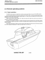
The Hamilton HSRX reverse system is a self contained hydraulic reverse actuation system.
The actuation is provided by a compact hydraulic reverse cylinder (3)* that uses a rotary valve(A) inside the
positioning
cylinder to give exponential poiitioning'contrá. Exponential posÍtioning is superior to proportional
position)
(around
zero
speed/reverse
the
is
needed
it
position
where
because it allows fine control of the cylinder
jet).
in
the
is
not
(when
the
duct
required
positioning
is
not
and fast controlwhere accurate
With the piston rest¡ction(A) fully open, equal pressure acts on both the rod end and cap end of the HSRX
cylinder. As the cap end area is larger than the rod end area, the cylinder extends,
Withthe piston restriction(A) closed, the cylinder retracts. Atfull retraction, the bypass valve (B) opens reducing
the system pressure and power consumption of the pump'
The back pressure valve(4) is factory preset at 3.45 MPa (500psi).
The pump (1) is belt driven directly from the waterjet'
*(Refer to Circuit diagram section 1.2)
HAMILTON
JET
22t5ts2
HSRX REVERSE
INTRODUCTION
1.2 Basic hydraulic circuit
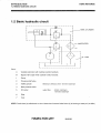
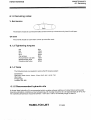
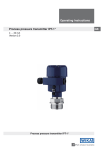
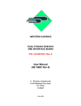
1.2 Basic hydraul¡c circuit
HSRX CYLINDER
*_
WATER FEED
-l
¡
I
ÏANK
-)'zr
Items:
A
Variable restrictíon with cylinder position feedback.
B
Bypass valve open when cylinder is fully retracted.
1
Pump
2
Pressure relief valve
3
HSRX
4
Back pressure valve
5
Oilcooler
cylinder
- Minimum oil flow 3
- water
flow
6
l/min
16 l/min maximum
l/min minimum
110|/min maximum
b
Filter
7
Tank
NOTE: Cooler ltem (5) will absorb 3.5 kw of heat when Pressure Relief Valve (2) is blowing al 1500 psi (103 MPa)
HAMILTON JET
18/08/e3
INTRODUCTION
1.3 Layout of comPonents.
HSRX REVERSE
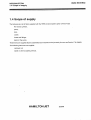
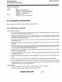
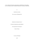
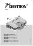
1.3 Layout of components.
CYLINDER
HAMILTON JET
1315192
HSRX REVERSE
INTRODUCTION
'1.4 Scope of supply
1.4 Scope of supply
jet;
The following is a list of items supplied with the HSRX reverse system option of the 273
RX reverse cylinder,
pump'
tank,
cooler,
hoses and fittings,
belts for the pump.
These items are supplied factory assembled and mounted on the iet ready for use. see Section 7 for details.
The following items are not supplied;
Hydraulic oil,
Cable or other actuating devices.
HAMILTON JET
zurys2
INSTALTATION
HSRX REVERSE
2.2 oil cooler water connestion
CHAPTER 2
INSTALLATION
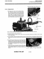
2.1 lnstalling the HSRX reverse system.
1. Remove the reverse duct as instructed in the 273 manual when inserting jet through transom hole.
2. After the jet has been mounted ¡n the boat and the reverse duct fitted, connect the reverse cylinder ensuring
that the cylinder shaft is up the same way as it was previously.
3. Check to ensure the dot on the end of the rod is uppermost. lf it is 180o out of rotation, then the HSRX
reverse will not work properly. To correct a 180o out of rotation rod, with the cylinder correctly mounted
(see Section 1.3) rotate rod using an adjustable wrench on the rod end flats. Do not grip the rod itself as
surface damage on the rod will damage the cylinder seals.
2.2 Oil cooler water connection
The cooler needs to be connected to the engine water offtake. lt does not have a lot of heating capacity so it
can be put between the otftake and the engine. Failure to connect the cooler will result in an excessive heat build
up and damage to system components.
To Engine
HAMILTON JET
2215192
HSRX REVERSE
INSTALI.ATION
2.3 Remote operating systems
2.3 Remote operating systems
2.3.1 Cable installation
The HSRX reverse system is supplied with a cable mounting plate (fitted to the end of the HSRX cylinder)
The recommended cable is the Morse 33c Supreme (low friction) cable. The cable mounting plate has been
designed to suit this cable. Other equivalent quality cables of 3" stroke should be suitable but may require some
modification to the cable mounting plate.
CABLE RUNS SHOULD NOT EXCEED 12m. Cable runs above this length may work but could result in a
reduction in reverse duct controlquality.
MINIMISE THE NUMBER OF BENDS. The diagram illustrates the jdeal arrangement for a dual stat¡on system.
Total bend angle per cable in this system is 180o. Do not exceed 3600 per total as this will result in excessive lost
motion (backlash).
Cable "Station Exchangef'systems mayallow reduced cable length and bends buttend to introduce excessive
lost motion (backlash) themselves. For cable runs longer than 12m, refer 2.3.3'
:,
HAMILTON JET
2119192
INSTALI.ATION
2.3 Remote operating systems
HSRX REVERSE
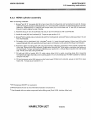
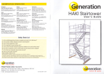
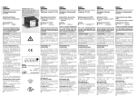
'Adjusting Ahead Travel Stop Screws
2.3.2 Adjustment
1. With the Control Lever in the full ahead position,
the HSRX lever should be touching the dowel
stop. Adjust the Control Lever full ahead stop
screw to achieve this with no Surplus Control
Lever travel. lf the cable control lever has no
stops, it will be necessary to adjust the cable
mounting position on the cable mounting plate
andlor the actuation radius at the control lever.
;; ' :uatt
detent pla
friction
i
screw
2. FILL THE OIL TANK WITH A BECOMMENDED OIL (see section 6.'1.5), to filler neck level.
3. Check belt tension (refer to Section 6.2.1).
4. ENSURE INTAKE lS UNDER WATER -either with the boat trailer reversed ¡nto the water or with the boat
moored SECURELY.
5. Hun the engine at idle, and rechecll refill oil in tank to the level shown on the dipstick. Move the Control
Lever slowly to fully lower and raise the reverse bucket several times. This will purge the hydraulic system
of air.
6. The Control Lever should now be moved to full astern
position. There is no astern stop for the HSRX Lever.
The full astern Control Lever stop should be adjusted
so that the reverse duct travels fully down (cuts across
the jetstream completely) with no Surplus Control
Lever travel.
lf more Control Lever movement is required (for greater
sensitivity) and spare cable movement is available, The
cable actuation radius at the Control Lever can be
altered.
HAMILTON JET
Adjusting Astern Travel StoP
Screw - Morse S Type Controller
2119192
HSRX REVERSE
¡NSTALLATION
2.3 Remote operating systems
7. Control Lever detent for Zero speed position:- lf ðesired the position of the Control Lever giving Zero Speed
can be determined on trials of the craft and the Control Lever detent position then adjusted to coincide'
NOTES:- Not all Control Leverse have aR adjustable detent.
- Hamiltons recommend any Control Lever detent action is de-astivated.(not used).
The reason is that Zero Speed position willvary with wind and tide and small movements either side of a
detented position become difficult.
2.3.3 Alternative remote operating systems
Manual - hydraulic Hynautic mounting kits are available as an option.
Pneumatic fleletronic, MMC etc)
Electronic
Consult Hamilton Jet if proposing to use an alternative remote operating system.
t
HAMILTON
JET
21ßts2
HSRX REVERSE
CORROSION
CHAPTER 3.
CORROSION
All Hamilton Jet manufactured components on the HSRX reverse system are made of high quality materials
selected for their good corrosion resistance performance. Some bought in items are of plaled steel' As.these are
inside the vessel, õorrosion should not be a problem. Should corrosion commence or if salt spray conditions are
likely to be encountered, we recommend the following;
1. Paint mounting bracket of remote mounting tank.
2. wrap anti corrosion tape (eg. Nippon Denso) around hydraulic fittings.
Note: it is possible to get stainless hydraulic fittings at a cost.
The oil cooler is protected by a zinc anode. This should be periodically checked.
HAMILTON
JET
24sts2
OPERATION
HSRX REVERSE
CHAPTER 4
OPERATION
There are a few points to note when using the HSRX reverse system.
the engine rpm, the
1) There is no flow control in the HSRX reverse system. The effect of this is, the higher
the reverse can be
full
speed)
at
(full
reverse
situation,
stoþ
ln the crash
faster the reverse will move.
actuated almost instantly causing a very sudden and severe deceleration.
position and
2) The HSRX reverse system does not have a mechanical connection between the reverse duct
has arrived
the control lever poéition. This means that the control lever can be positioned before the duct
the duct
leverfollowed
control
wherethe
atthe desired poiition (unlike the previous HSRC systems used
Position).
is touching the dowel stop, the
O) The HSBX reverse system has a bypass feature. When the control lever
oil is then passed directly to
opens.
valve
bypass
position
a
and
raiåäd
reverse duct will be in the fully
pressure,
tank rather than over the back pressurb vafue. The pump will operate at cons¡derably reduced
minimise power consumtion and maximise component lives'
HAMILTON JET
2215192
HSRX REVERSE
FAULT FINDING
CHAPTER 5
FAULT FINDING
Fault
Symptom
RePair
down - back pressure too low
does
rpm.
Duct will not lifi out of reverse - back pressure too high
back pressure should be
factory set at 500psi. Check
and adiust if it is below this.
Duct does not go fully
with high enginé rpm, or
not sta! down with high
same as if back pressure too low
with high engine rpm, relief
valve blowing.
Excessive heat
buildup
- Cooler
blocked
Bypass not
Duct does not move at all,
controller
freely
- Cannot move
- Controller moves
- Unblock, remember to check
water level on boat before
removing hoses.
- Adjust as per Secion 2'3'2
working
cable
- Broken cable
- Unjam or replace
- Replace cable
- Jammed
- Hydraulic failure
- Could be due to;
belts
sliPPing
system
oil.
hose
Broken PumP
Belts
Blockage in
Run out of
Split
- RePlace belts
- Adjust tension
- Disassemble & clean
- Refill
- RePlace
- Jammed cylinder
- Could be due to
Bent
System looses
oil
- Leak in
rod
- RePlace Hod
Hydraulics
- Damaged cylinder
LeakY
synchronised
lever
Duct not
with
seal
-Cylinder rod 1800 out of
HAMILTON
rod
phase
JET
- Replace ortighten
-This can damage seals,
Replace both rod and seals
- RePlace
- Rotate cylinder rod so that the dot
on the rod end is uppermost as in
Section 2.1
zustsz
HSRX REVERSE
MAINTENANCE
6.1 Servicing
CHAPTER 6
MAINTENANCE
6.1 Seruicing
6.1.1 Schedule
Afier First 5 hours
Change oil
Change oil Filter element
After First 100 hours
Change oil
Change oil Filter element
Daily
Check oil level in tank
Check for leaks
Check oil condition and replace if discoloured or contaminated
Check V belt tension and belt condition
Checkfor loose cable linkages
Check control lever moves freelY
Monthly
Check the actuation lever contacts the dowel stop in the full ahead cable control lever positionCheck the reverse duct completely cuts the jet in the full astern position
Adjust where necessary
Lightly grease pivot ball of reverse cylinder
Check anode on oil cooler, Replace if required
Every 1000 hours running
Change oiland filter.
Replace hydraulic oil and filter after first 100 hours. From then on change filter and oil every 1000 hours or whenever oil/filter condition require replacement.
HAMILTON
JET
nn2/s2
MAINTENAÍ,¡CÉ,
6.1 Servicing
HSRX REVERSE
6.'{..2 Seruicing notes:
V. Belt tension
The tension should be such that the belts can be moved up or down 8mm by hand in mid span.
Oil level
The oil level should be such that it comes up to the filler neck.
6.1 .3
Tightening torques
M6
M8
M10
M12
Cap screws
Pump tension nuts (22)
Backpressure valve
Pressure relief valve
5Nm
12Nm
24Nm
¿15Nm
5Nm
12Nm
40Nm
40Nm
6.1.4 Tools
The following tools are required to service the BX reverse system:
Screwdriver
Spanners, sizes 1 Omm, 1 3mm, 1 7mm, 3116',
Allen keys
Thread tape
Loctites;262, 680
31 4",
19116', 7 18"
6,1.5 Recommended hydraulic oils
A mineral base hydraulic oil is recommended which contains antiwear additives of a type that are active under
boundary lubrica:tion conditions at low temperatures. Oil viscosity should be 20 c St aþproximalely at 40oC. Normal operating temperature should lie between +30oC and +60oC. Oilviscosity range 10-300c St.
HAMILTON JET
17112192
HSRX REVERSE
MAINTENANCE
6.2 Assembly instructions
Suitable oils might include:
Brand
Shell
Gastrol
O¡l
RIMULA 10W (Crankcase oil)
DONAX TM (Auto transmission oil)
(Auto transmission oil)
DEXRON
(hYdraulic oil)
Tellus
HysPin AWS 22
Transmax (Auto transmission oil)
2
46
6.2 Assembly ¡nstructions
Note: disassembly follows the reverse of the assembly procedures'
6.2.'l Hydraulics assembly.
Refer to drawing 106549SY
1. Mount block (10)
and'O'ring
(38) to pressure port of pump (1). Mount manifold(32) to suclion port, torque
socket head cap screws to as per section 6.1.3.
(3) and,(2) using
2. Assembly side load adaptor (Q to pump (1) and attach front and rear mounting plates
adaptor.
pulley
sideload
onto
Mount
per
6.1.3.
qzzi,qâe¡,(zs).
section
Toi{ue
as
bolrs, nurs áno wàsnerå
Torque M12 nut as Per section 6'1.3
1500 PSI). Torque
3. Fit pressure relief valve, (12)to block (10). Checkthatvalve is VM0a1/E-2{0 (preset at
as per section 6.1.3.
4. Mount pump assembly on bearing housing (6) using bolt nuts and washers (22 to 26) as per drawing
106549sY.
s. Fit belts(13) and tension by levering pump body away from intake and tightening nuts (22) as per section
top of
6.1.3. The correct tensionhas bee-n'acnieved when þushing one of the belts down by hand at the
the belt lies level with the bottom of the remaining belt.
mounting
6. Mount the oil tank (7), using studs, nuts and washers (31)(36)(37) in the upper two holes in the
bracket on the waterjet intake..
Z. FrTgl4" BSp hosetail (18) to pump suction manifold (32) using thread tape. Connect up suction hose (20)
using jubilee clips (21).
jubilee clip
8. Fit 5/8,' pushlock fitting (33) to block (10) using thread tape. Connect up 5/8" return line using
(21).
9. Mount oil cooler (8) on bearing housing (6) using elamp (9), and studs, nuts, washers (22)(23)(26).
10. FA g/A,,nipple adaptor (04) dowrywasher (14) and 3/8" pushlockfitting (15) (with thread tape) to block(10).
11. Fit high pressure hose (16), routing forward of inspection cover. Fit 3/8" pushlock hoses (17) between
HSRX cylinder (30), oil cooler (8)and block(10).
GeneralNotes
1. Thread
tape should be used on all BSPT to BSPP (parallel to taper) connections'
2. Push lock hoses should be renewed if disassembly is required.
HAMILTON JET
nt12ts2
MAINTENANCE
6.2 Assembly instructions
HSRX REVERSE
6.2.2 HSRX cylinder assembly
Refer to drawing 106554SY
1. GreaseA and fit 'O' ring seds (a)(15) to back head (19), fronthead (3) and hemispherical seat (8). Grease
andfitGTring(16)toplston-shaftassembly(11).Checkthatthe scarfjointonsealbackingringiscorrectly
mated up. Grease and fit'U' seal (9) and scraper seal (10) to front head and 'U' seal (20) to backhead.
Ensure U seal is aligned as per drawing.
2. Assemble stop pin (13) ln backhead (19) and pin (5) in fronthead (3) wilh LOCTITE 680.
3. Loctite tie rods (30) into fronthead (3). Torque as per section 6.1.3.
4. GreaseA both outside ends of cylinder (2) and fit to fronthead (3); lubricateB piston shaft assembly
fit to
fronthead(3).
(1
1
) and
i
5. Fit bearing (18) to backhead (19). LubricateB spool (1), insert through bearing (18)and seal (20) whilst
supporting seal (20) and assemble backhead spool combination onto cylínder fronthead combination.
6. Assemble cable mounting plate (34) and nuts/washers (28)(29) to backhead. Hold cylinder upright with
rod at top. Ensure rod is fully retracted. Rotate spool through 360" (this helps to centralize the bearing in
the backhead). Torque nuts/washers (28)(29) as per section 6.1.3. Mount Nylon washer (21) and handle
(23). Fit set screw (22) using loctite 262.
7. Fit ball joint (26) to handle (23). Fit cable clamp kitset (24) to cable mounting plate (34). Assemble
hemispherical selts (7)and(8), and mounting plate (17) onto fronthead (3). Fit HSRX cylinder to water jet
using tie rod (33)u.
8.
A
Fit back pressure valve (38) (pressure relief valve type) CP20B-3-B-O-A-B-050, preset
head (19) . Torque as per section 6.1.3.
BP Energrease MM EP2 or equivalent.
e Mineral based oil such as recommended hydraulic oil (section 5)
c Coat threads with non
seize compound before fitting nuts (Rocl YIGG, Jet-lube, Nikal, etc).
HAMILTON JET
18/08/eg
at 500 PSI to back
HSRX REVERSE
MAINTENANCE
6.3 lnstalting the HSRX as a Retrofit.
6.3 lnstalling the HSRX as a Retrofit.
6.3.1 Removing Manual Reverse
7'DF,,,,,
Z¡. Pull duôt down and push out pin (1a) to disconnect toggle (3)
1.
Unscrew tocknut (13) and remove boú
from cable.
2.
Push duct to full up position and release springs (5) lower duct and rest on deflector.
3.
Remove Cam plate (2) by unscrewing 2 nuts (11).
4.
Unscrew Reverse cable from ball and tube assembly (1) and pull cable out.
E
Unscrew 4 M6 Nuls that hold ball and tube assy (1). Remove ball & tube assy.
1f
6.3.2 Changing the bearing housing.
- refer section 6.2.1 for instructions to.
1.
Remove bearing housing.
2.
Change bearing and seals to HSRX bearing housing.
3.
Re-assemble jet with new bearing housing.
6.3.3 Assembly of hydraulics
- see section 6.2.1 in HSRX Manual.
HAMILTON JET
17112192
HSRX
REVERSE
PARTS LISTS / DRAWINGS
7.1 General components(Excluding HSRX cylinder)
CHAPTER 7
PARTS LISTS / DRAWINGS
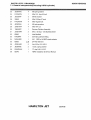
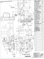
7.1 General components(Excluding HSRX cylinder)
Referto Drawing 106549SY at rear
Item
1
2
3
4
5
6
7
I
I
10
11
12
13
14
15
16
17
18
19
20
21
22
Number
63672SY
106551
106550
106u153
104154
106553
63681
63670
106570
95124
JBJYXAE
63674
63676
JENXAAO
HXIOBAD
66059
66062
HXIOBAH
66063
66061
HSIJAAU
JDQHXAC
Part
Qty.
Description
1
1
1
1
1
1
1
1
1
1
4
1
2
1
1
t
2
1
1
1
2
4
3.8cc pump with side load adaptor
Rear mounting plate - pump assembly
front mounting plate - pump assembly
pulley
coupling flange
bearing housing
oiltank
oilcooler
oilcooler mounting bracket
PRV block
M6xlxs0 socket head cap screw
VM041/1 pressure relief valve
V belt (SPZ670)
dowtywasher3/8"BSP
push lockfitting 3/8"BSP male
hose assembly 3/8" BSP
3/8"8SЀ80 pushlock hose
Pushlock Fitting 1/2" BSP Male
5/8"8SPx500 pushlock hose
3/4"8SFx500 suction hose
314' Jubilee hose clip
MBx1.25 nut
HAMILTON
JET
2srczßs
PARTS LISTS / DRAWINGS
7.1 General components(Excluding HSRX cylinder)
23
24
25
26
27
28
29
30
31
32
33
34
35
36
37
38
39
JEQICßC 4
HYQHXCJ 1
JEO¿(AF 3
30665
3
HYQHXAK 4
JEQIO(AA 4
JDQHXAA 4
106554SY 1
JCQHXAN 2
63680
1
HXIOBAF 1
NZAAJBD 1
63682
ff
JDQHXAE 2
JEQICßE 2
HMHRAAH 1
82046
1
HSRX REVERSE
MB spring washer
M8x1.25 - 69 x 80 bolt
MB flat washer
MBx1.25€g rP7 stud
M6x1€9x80 bolt
M6 spring washer
M6x16H nut
Reverse C\TlinderAssembly
M10 x 4O Stud - 316 Stainless Steel
lnlet Manifold
s/8"male pushlock fitting
3/8"
BSP to 3/8"BSP nipple adaptor
ZF Filter Element
Nut, M10x1.5 316 S.S.
1A Dia. spring washer
'O' ring 0.09 X 0.5 lD.
HSRX lnstallation & Service Manual
HAMILTON
JET
25rc2ßs
HSRX REVERSE
PARTS L¡STS / DRAWINGS
7.2 HSRX Cylinder
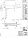
7.2 HSRX Cylinder
Hefer to drawing 106554SY at rear
No.
106560
106555
106557
Oty
Item
Part
1
2
3
4
5
6
7
I
9
10
1
12
13
14
15
16
17
18
19
20
21
22
23
24
25
26
27
28
1
1
1
HMHRAEW 2
1
105927
105945-1 1
1
106563
1
106564
JWIGAEF 1
JWI(ZAEE 1
106559SY 1
HXIOBAD 1
106558/1 1
1
106503
HMHRAÐ( 1
JWTGADD 1
1
105572
JNODAFY 1
106558
1
JW(ZAEG 1
JENYAAG 1
JAJYXBC 1
t
106561
1
80934
JDQSAAA 2
I(YINAAF 1
1
Description
Spool
CYlinder
Fronthead
'O'seal3/32'X1.424'X1.630"
pin
insert
front hemiseat
rear hemiseat
seal20)2ÐK5.0 UHS 20
scraper20)28x5.3 MN078110
Shaft assY.
3/8"BSP pushlock fitting (male)
stop pin
pivot pin
'O'seal type 131 3/32d.612"i1d)
Piston sealGT 8065-173-HR
mounting plate
bearing SKF 6301
backhead assy
seallå€0x5.0 PM1825
Washer nylon 826250
M6x10 sK set screw 316 S.S.
handle
cable clamp set
nylon insert nut 3/16"UNC S.S.
balljoint Morse 0317'99-001 (3/16')
1(ref) balljoint (1/4')
JDQHXAA 8
M6 nut 316 S.S.
HAMILTON JET
2st1ots2
PARTS LISTS / DRAWINGS
7.2 HSRX Cylinder
HSRX REVERSE
29
30
31
32
33
34
35
36
37
38
JEQI{üA
106556
NTAAJBD
JENXAAO
106413-1
106562
HUll AAA
JEOZXAI
JENYMH
63697
4
4
1
1
4
1
1
1
2
1
M6 spring washer
tie rod
Nipple for dowty seal (3/8"BSPP)
dowtywasher
tie rod
cable mount¡ng Plate
split pin S.S.
M10 washer
Washer-nylon 610)ß2(1.6
Pressure Relief Valve
Spares kit
Filter (oiltank)
Cylinder seals
kitset
f
A69q
s.rn\.k. aÇ4sq
4,1't'3
HAMILTON
JET
zstlotsz