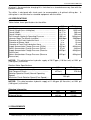
1
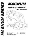
Instruction Manual MW-80H
INSTRUCTION MANUAL
For
HYDRAULIC DRIFTER
Model:
MW-80H
Read this Instruction Manual before operating this equipment.
-1WOLF–Metalúrgica – Tel: +55 (19) 3875 6555 – Fax: +55 (19) 3875 5460 – e-mail: [email protected] - site: www.wolf.com.br
Instruction Manual MW-80H
WARRANTY
WOLF – Metalúrgica, warrants that all replacement parts supplied by it will be free from
defects in materials and workmanship for a period of three months from date of supply
when operating under normal working and environmental conditions. If a failure occurs
which is due to defects in materials or workmanship during the period, WOLF - Metalúrgica
will replace the item. This Warranty shall not apply to any WOLF - Metalúrgica product
which shall have been altered, or modified in any way. We shall not in any event be liable
for the cost of any special, indirect or consequential damage to any one.
WOLF will provide a new part or repaired part, at its election, in place of any part which is
found upon its inspection to be defective in material and workmanship during the period
prescribed above. All warranty parts will be replaced FOB Wolf factory in Indaiatuba-SP,
Brazil.
This warranty does not apply to failures occurring as a result of abuse, misuse, negligent
repairs, corrosion, erosion and normal wear and tear, alteration or modification made to
the product without express written consent of WOLF – Metalurgica; or failure to follow the
recommend operating practices and maintenance procedures as provided in the product’s
operation and maintenance publication.
Equipment and part furnished by WOLF – Metalurgica, but manufactured by others, shall
carry whatever warranty the manufactures have conveyed to WOLF – Metalúrgica and
which can be passed on to the initial user.
Wolf Metalúrgica shall not be liable for loss of time, manufacturing cost, labor, material,
loss of profit, consequential damages, direct or indirect, because of defective products,
whether due to right arising under the contract of sale or independently thereof, and
whether or not such claim is based on contract, tort or warranty.
The customer agrees to care for the equipment properly, to use it within its rated capacity,
to restrict its use to the customer’s qualified personnel and to prohibit anyone other than
the buyer's qualified mechanic from making repairs to, modifying, or adjusting the
equipment.
The customer assumes full responsibility for damage, loss or destruction of the equipment
from the date of delivery. The customer, at his own expense, shall maintain the equipment
and replace or change all spare parts or perform all necessary labor according to the
equipment's Operator's Service Manual. The customer further agrees to pay for all
damage to the equipment resulting from causes other than normal wear and tear upon
receipt of invoice from the WOLF - Metalúrgica cost and expense for the repair. The
customer shall take care of normal needs of the equipment including supplying fuel,
grease, tires, oils, cooling system, water, recharging batteries, etc. The customer will
perform any other routine service and preventive maintenance set forth in the Operators
Service Manual for the equipment.
If the customer requires for further assistance or service from the factory, the cost is for
customer account.
Written permission of any warranty claim return must be first obtained from authorized
WOLF personnel. All returns must be accompanied with a complete written explanation of
claimed defects and circumstances of operational failure.
-2WOLF–Metalúrgica – Tel: +55 (19) 3875 6555 – Fax: +55 (19) 3875 5460 – e-mail: [email protected] - site: www.wolf.com.br
Instruction Manual MW-80H
Products manufactured or sold by WOLF are not warranted expressly or implication for
merchantability or fitness or for any measure of service or suitability of for a specific
purpose notwithstanding any disclosure to WOLF of the use to which the product is to be
put. This express warranty is to solve warranty of WOLF there are no warranties which
extend beyond the warranty herein expressly set forth. The sales of products of WOLF
under any other warranty or guarantee express or implied is not authorized.
This Warranty shall not apply to any WOLF - Metalúrgica product which shall have been
altered, or modified in any way. We shall not in any event be liable for the cost of any
special, indirect or consequential damage to any one.
-3WOLF–Metalúrgica – Tel: +55 (19) 3875 6555 – Fax: +55 (19) 3875 5460 – e-mail: [email protected] - site: www.wolf.com.br
Instruction Manual MW-80H
WOLF - Metalurgica
The Hydraulic Drifter described in this literature is manufactured by WOLF exacting
standards.
For maximum utilization and efficiency in operating this equipment, we urge you to
thoroughly read the entire contents of this manual before you begin to drill.
-4WOLF–Metalúrgica – Tel: +55 (19) 3875 6555 – Fax: +55 (19) 3875 5460 – e-mail: [email protected] - site: www.wolf.com.br
Instruction Manual MW-80H
TABLE OF CONTENTS
TOPICS
1. Introducing this manual
2. Abbreviation List
3. Safety First
3.1 Safety Alert Symbol and Signal Words
3.2 Safety Precautions
4. Introduction for Hydraulic Drifter MW-80H
4.1 Descriptions
4.2 Specifications
5. Requirements
5.1 Hydraulic Requirements
5.2 Lubrication Requirements
5.3 Air Requirements
5.4 Hoses and Fittings
5.5 Basic Operating Principles
5.6 Drill Piston Reciprocation
5.7 Drill Steel Rotation
5.8 Operating Controls
5.9 Charging the Drifter Accumulators
5.10 Connecting the Striking Bar
5.11 Drilling Procedures
5.12 Drilling Tips
5.13 Suggestions for Drillers
5.14 Drill Steel Care
5.15 Bit Care
6. Disassembly, Inspection and Assembly
6.1 Hydraulic System
6.2 Hoses
6.3 Drifter
6.4 Lubricant Specifications
6.5 Hydraulic Oil
6.6 Front End Lubricating Oil
6.7 Drill Steel Thread Lubricant
6.8 Maintenance
6.9 Drifter Disassembly
6.10 Hydraulic Rotation Motor Disassembly
6.11 Inspections of Parts
6.12 Accumulator Reassembly
6.13 Hydraulic Rotation Motor Reassembly
6.14 Inspection of Accumulator Pressures
7. Troubleshooting
Page
5
5
5
6
6
8
8
9
10
10
10
10
10
11
11
11
11
11
12
13
13
13
13
14
15
15
15
15
16
16
16
17
17
18
20
21
23
23
24
26
-5WOLF–Metalúrgica – Tel: +55 (19) 3875 6555 – Fax: +55 (19) 3875 5460 – e-mail: [email protected] - site: www.wolf.com.br
Instruction Manual MW-80H
1. INTRODUCTION
This instruction manual contains information for safety, operation, maintenance, service
information, troubleshooting for the drifter MW-80H (here-after referred to as drifter).
2. ABBREVIATION LIST
Abbreviation, Symbol or Term
A
C
Etc.
Ft.
F
FDO
GO
HO
HP
Hr.
In.
IM
Kg
Kg/cm2
Km
Km/hr
Kw
Lb-ft
L
L.H.
Max.
Min.
Mm
MPa
Mph
M
MO
M3/min.
Nm
Pt
Pl
Psi
RDO
R.H.
SCFM
Tl
RPM
Meaning
All- Purpose Grease
Celsius (Temperature)
Etcetera
Feet
Fahrenheit (Temperature)
Final Driver Oil
Gear Oil
Hydraulic Oil
Horsepower
Hour
Inches
Instruction Manual
Kilogram
Kilograms per Square Centimeter
Kilometer
Kilometer per Hour
Kilowatts
Pound Feet
Liter
Left Hand
Maximum
Minimum
Millimeter
Mega Pascal
Miles Per Hour
Meter
Motor Oil
Cubic Meters per Minute
Newton Meter
Pint
Part List
Pounds per Square Inch
Rock Drill Oil
Right Hand
Standard Cubic Foot Per Minute
Thread Lubricant
Revolution Per Minute
3. SAFETY FIRST
-6WOLF–Metalúrgica – Tel: +55 (19) 3875 6555 – Fax: +55 (19) 3875 5460 – e-mail: [email protected] - site: www.wolf.com.br
Instruction Manual MW-80H
This section contains important information for the Top Hammer MW-80H (here-after
referred to as drifter).
Safety First is the primary concern for the protection of both, personnel and the machine
during any phase of operation. All personnel must thoroughly understand all safety
precautions before operating or doing any maintenance work on the machine.
3.1 Safety Alert Symbol and Signal Words
This is the Safety Alert Symbol. When you see this symbol on the machine or in this
instruction manual, be alert to presence of a hazard.
All Personnel must understand the DANGER, WARNING, CAUTION, and NOTICE used
throughout the next of this instruction manual. The DANGER, WARNING, CAUTION, and
NOTICE are defined as follows:
DANGER
Danger is used to indicate the presence of a hazard, which will
cause severe personal injury or death if warning is ignored.
WARNING
Warning is used to indicate the presence of a hazard which
can cause severe injury or death if warning is ignored.
CAUTION
Caution is used to indicate the presence of a hazard which will
or can cause personal injury, or property damage if the
warning is ignored.
NOTICE
Notice is used to notify people of installation, operation, or
maintenance information, which is important, but not hazard
related.
By understanding what DANGER, WARNING, CAUTION, and NOTICE mean: and using
good judgment and common sense, all personnel can avoid injuring themselves and or
damaging the machine.
3.2 Safety Precautions
a) DO NOT ATTEMPT TO OPERATE THE HYDRAULIC DRIFTER UNLESS YOU ARE
THOROUGHLY FAMILIAR WITH ALL THE CRAWLER GAUGES, CONTROLS, AND
-7WOLF–Metalúrgica – Tel: +55 (19) 3875 6555 – Fax: +55 (19) 3875 5460 – e-mail: [email protected] - site: www.wolf.com.br
Instruction Manual MW-80H
FUNCTIONS. REFER TO THE SECTION OF THE CRAWLER INSTRUCTION BOOK
FOR DETAILED INSTRUCTIONS. FAILURE TO COMPLY COULD RESULT IN BODILY
INJURY.
b) ALWAYS WEAR APPROVED HARD HAT, SAFETY SHOES, SAFETY GLASSES,
NOSE MASK AND EAR PROTECTION WHEN NEAR A DRIFTER IN OPERATION.
c) KEEP HANDS, ARMS, LEGS AND CLOTHING AWAY FROM ALL MOVING PARTS.
FAILURE TO COMPLY COULD RESULT IN BODILY INJURY.
d) THE DRIFTER, STRIKING BAR, COUPLINGS, DRILL STEELS AND BIT ARE HOT
DURING THE DRILLING OPERATION. DO NO TOUCH THESE PARTS WITH YOUR
BARE HANDS. WEAR GLOVES TO PROTECT YOUR HANDS WHEN YOU ARE
CHANGING BITS OR STEELS. A SEVERE BURN WILL RESULT IF ROTATING PARTS
ARE TOUCHED WITH BARE HANDS.
e) KEEP ALL HOSE CONNECTIONS TIGHT. A LOOSE HOSE CONNECTION NOT
ONLY CAUSES LEAKS AND POOR PERFORMANCE, BUT MAY ALSO ALLOW THE
HOSE TO COME OFF THE DRIFTER, WHIP AROUND, AND INJURE THE OPERATOR
OR OTHER PEOPLE IN THE AREA.
f) MAKE SURE THAT THE PARTS-CLEANING SOLVENT IS NON-FLAMMABLE, WILL
NOT HARM THE SKIN, MEETS CURRENT SAFETY AND HEALTH STANDARDS, AND
IS USED IN WELL VENTILATED AREA.
g) DRY NITROGEN IS THE ONLY GAS PRODUCT TO BE USED TO CHARGE THE
DRIFTER ACCUMULATORS.
NEVER USE OXIGEN TO CHARGE THE
ACCUMULATORS. IGNITION OF AN OXIGEN AND OIL MIXTURE COULD PRODUCE
AN EXPLOSION, WHICH COULD SEVERELY INJURE PERSONNEL IN THE AREA.
h) MAKE SURE THE ACCUMULATORS ARE IN GOOD CONDITION. MAKE SURE
THE ACCUMULATOR COMPONENTS HAVE NO CRACKS OR SIGNS OF EXCESSIVE
WEAR. WHEN PRESSURIZED, A DAMAGED ACCUMULATOR COULD BURST,
SCATTERING METAL FRAGMENTS THROUGHOUT THE AREA WHICH COULD
SEVERELY INJURE PERSONNEL.
i) BE SURE TO BLEED THE ACCUMULATORS BEFORE ANY ACCUMULATOR
DISASSEMBLY IS ATTEMPTED.
-8WOLF–Metalúrgica – Tel: +55 (19) 3875 6555 – Fax: +55 (19) 3875 5460 – e-mail: [email protected] - site: www.wolf.com.br
Instruction Manual MW-80H
4. INTRODUCTION
This section provides a description and specifications of the Hydraulic Drifter MW-80H
(hereafter referred to as drifter).
4.1 DESCRIPTION
The hydraulic drifter is a valved, hydraulically-operated hammer drill that incorporates and
integral, independently-controlled, hydraulically-powered rotation motor to rotate the drill
steel and bit.
The drifter is capable of drilling 3 to 4 in. (76 to 100mm) diameter holes in all types of rock
formations. It is especially suitable for pipeline work, drilling vertical and angle blast holes
in quarries, and on any construction jobs where large volume rock excavations are
required.
Since the drifter is hydraulic, there are only two moving parts to control hammer action:
the piston and the piston valve. The piston provides the impact force which is transmitted
to the drill steel. The valve alternately switches pressure from supply to exhaust. This
action produces a high frequency reciprocation of 2600 cycles per minute. The piston
strikes the striking bar on each forward (power) stroke, thus, transmitting the blow energy
through the steel to the bit at 2600 blows per minute.
The hydraulically-powered rotation motor is independently controlled and is designed to
provide continuous drill steel rotation-forward or reverse. The motor converts hydraulic
fluid to rotation power and transmits the rotation power to the spur gear train housed in the
drifter fronthead. The hydraulic rotation motor provides smooth, powerful rotation,
especially at low rotation speeds, and assures the operator of positive rotation control
under all drilling conditions.
Since hammer action and drill steel rotation are independently controlled, the best
combination of individual control of both functions can be selected for the most efficient
drilling in a particular formation.
Since the drifter operates on hydraulic fluid power, instead of air, its operation is
unaffected by altitude. In addition, there is no noise from air exhaust and no fog buildup in
working areas.
The only air requirements for the drifter are: for hole cleaning and fronthead lubrication.
The drifter is equipped with a ¾ in. (19mm) outside diameter blower tube which carries
hole cleaning air from the inlet connection in the backhead, through the center of the
drifter, striking bar, drill steel and bit to the bottom of the hole without contacting any of the
internal parts of the drifter.
CAUTION
THE DRIFTER ACCUMULATORS REQUIRE CHECKING
EVERY 250 HOURS OF OPERATION.
The drifter uses two nitrogen-charged diaphragm accumulators to dampen vibrations in the
supply and return hoses. The supply line (high pressure) accumulator must be charged to
853 psi (60 kg/cm²). The return line (low pressure) accumulator must be charged to 57 psi
-9WOLF–Metalúrgica – Tel: +55 (19) 3875 6555 – Fax: +55 (19) 3875 5460 – e-mail: [email protected] - site: www.wolf.com.br
Instruction Manual MW-80H
(4 kg/cm²). An accumulator charging kit is furnished as a standard accessory item with the
hydraulic machine.
The drifter is designed with chuck parts to accommodate a 6-splined striking bar.
striking bar is not furnished as standard equipment with the drifter.
A
4.2 SPECIFICATIONS
Tables below show specifications for the drifter.
Net Weight ………………………………...…........…...........
Overall Length (less striking bar) ………………...…….......
Overall Width …………………………………………............
Overall Height …………………………………………...........
Drill Hammer Hydraulic Operating Pressure …………........
Hammer Blows Per Minute (variable) …………………........
Diameter of Drill Inlet Hydraulic Hose ………………….......
Diameter of Blower Hose …………………………….….......
Diameter of Front End Lubrication Hose ………….…….....
Supply Accumulator Charge Pressure (Drifter) ……...…....
Return Accumulator Charge Pressure (Drifter) …………....
Supply Accumulator Charge Pressure (Reverse
Percussion)
Return Accumulator Charge Pressure (Reverse
Percussion)
U.S.
463 lb.
40.35 in.
14.17 in.
11.61 in.
1991 psi
2600 bpm
¾ in.
¾ in.
3/8 in.
853 psi
57 psi
853 psi
Metric
210 Kg
1025 mm
360 mm
295 mm
140 kg/cm²
2600 bpm
19 mm
19 mm
i.5 mm
60 kg/cm²
4 kg/cm²
60 kg/cm²
853 psi
60 kg/cm²
NOTICE: This data based on hydraulic supply of 29.27 gpm (110 liters/min) at 1991 psi
(140 kg/cm²) at the inlet.
Rotation Motor Specifications
Diameter of Hydraulic Hoses (2) ..……………......
Stall Torque at Chuck ………………………..........
Rotation Speed at Chuck (Normal Operating
Speed)
Maximum Chuck Rotation Speed (Free Speed).....
U.S.
Metric
½ in.
12.7 mm
427 lb-ft
578 Nm
0 to 150 rpm
150 rpm
NOTICE: This data based on hydraulic supply at 11.89 gpm (45 liters/min.) at 1991 psi
(140 kg/cm²) at the inlet.
Shipping Information
Net Weight of Drifter ………………………...............
Shipping Weight ………………...…………..............
U.S.
463 lbs
483 lbs
Metric
210 Kg
219 Kg
5. REQUIREMENTS
- 10 WOLF–Metalúrgica – Tel: +55 (19) 3875 6555 – Fax: +55 (19) 3875 5460 – e-mail: [email protected] - site: www.wolf.com.br
Instruction Manual MW-80H
This section provides air requirements, operating principles, hydraulic requirements, and
lubrication requirements of the Hydraulic Drifter MW-80H (hereafter referred to as drifter).
5.1 HYDRAULIC REQUIREMENTS
The hydraulic power required to operate the drifter is divided into two independent
functions:
a.
Hammer Operation – The hydraulic system must be capable of supplying
hydraulic fluid to the drifter at a rate of 29.27 gpm (110 liters/min.) at 1991 psi (140
kg/cm²).
Drill Steel Rotation – The Hydraulic system must be capable of supplying
hydraulic fluid to the rotation motor on the drifter at a rate of 11.89 gpm (45 liters/min.)
at 1991 psi (140 kg/cm²).
b.
WOLF hydraulic crawler machines are designed to use this hydraulic drifter. Basically, its
hydraulic system contains a fluid reservoir, which stores a supply of hydraulic oil; pumps,
which develop and deliver the required hydraulic oil pressure and flow to operate the drifter
and its rotation motor; filters for removing particulate contamination from the oil supply,
control valves to initiate hammer action and control the speed and direction of the rotation
motor; and an oil cooper to maintain the entire system at an optimum operating
temperature. An arrangement of hoses and fittings carries the oil from the reservoir
through the pumps and regulating controls to the drifter and rotation motor and back to the
reservoir through the oil cooler.
5.2 LUBRICATION REQUIREMENTS
The Drifter uses an oil mist to provide lubrication to all critical points in the front end of the
drifter. A 3/8 in. (9.5 mm) diameter hose, connected to the drifter, carries the oil-laden air
from a lubricator (part of drilling machine), to the front end of the drifter. The amount of
lubrication provided is controlled by the lubricator located on the drilling machine.
5.3 AIR REQUIREMENTS
The air requirements for the drifter are for front end lubrication and hole cleaning. For
normal drilling conditions, a minimum flow of 10 scfm (0.28 m³/min.) at a pressure of 100
psi (7.03 kg/cm²) is required for lubrication and the remaining air for hole cleaning.
5.4 HOSES AND FITTINGS
Only quality hose designed especially for rock drill service should be used. It should be
constructed with an outer covering which resists abrasive wear and have a working
pressure safety factor of at least 4 to 1 in relation to burst.
Hoses and hose fittings must be in good condition, and the fittings must be kept tight.
The following lists the hoses required to operate the drifter and the diameter of each hose:
a.
b.
c.
d.
e.
Inlet Hydraulic Hose - ¾ in, (29 mm) diameter.
Return Hydraulic Hose - ¾ in. (19 mm) diameter.
Forward Rotation Hydraulic Hose - ½ in. (12.7 mm) diameter.
Reverse Rotation Hydraulic Hose - ½ in. (12.7 mm) diameter.
Front End Lubrication Hose – 3/8 in. (9.5 mm) diameter.
- 11 -
WOLF–Metalúrgica – Tel: +55 (19) 3875 6555 – Fax: +55 (19) 3875 5460 – e-mail: [email protected] - site: www.wolf.com.br
Instruction Manual MW-80H
5.5 BASIC OPERATING PRINCIPLES
The operation of the drifter is based on two independent basic operating principles: (a) the
principle that causes the piston to reciprocate (hammer action) and (b) the principle
governing the drill steel rotation.
5.6 DRILL PISTON RECIPROCATION
The drifter is a valved hydraulic drill. The valve cylinder assembly and cylinder liner
convert hydraulic fluid pressure into efficient hammer action. The piston within the cylinder
liner provides the impact force which is transmitted to the drill steel. The valve alternately
switches pressure from supply to exhaust. This action produces a high frequency
reciprocating action of 2600 cycles per minute. The piston strikes the striking bar on each
forward (power) stroked, and through the striking bar and steel, drives the drill bit into the
rock at 2600 blows per minute.
5.7 DRILL STEEL ROTATION
The drifter is designed with an independently-controlled, hydraulic-powered, rotation motor
that provides continuous drill steel rotation–forward or reverse.
The motor converts hydraulic fluid to rotation power and transmits the rotation power to a
drive gear which is part of the spur gear train housed in the drill fronthead. Thus, as the
drive gear is rotated, the meshing chuck gear and mating chuck driver follow the rotation.
Splines within the chuck driver mate with those in the striking bar, thereby imparting the
rotation through the drill steel to the bit.
5.8 OPERATING CONTROLS
Hammer action, drill steel rotation and feed are controlled separately and each must be
regulated for optimum results in the drilling conditions encountered. All operating controls
for the drifter are located on the drilling machine console. Refer to the operation section of
the drilling machine instruction book for detailed descriptions and instructions covering all
operating controls and gauges.
5.9 CHARGING THE DRIFTER ACCUMULATORS
The drifter uses nitrogen accumulators to dampen vibrations in the pressure and return
hoses. Before operating the drifter, both accumulators must be charged.
NOTICE
An accumulator charging kit is furnished as a standard
accessory item with the drilling machine.
The following DANGER Precautions must be observed when charging the drifter
accumulators:
DANGER
DRY NITROGEN IS THE ONLY GAS PRODUCT TO BE
USED TO CHARGE THE DRILL ACCUMULATORS. NEVER
- 12 WOLF–Metalúrgica – Tel: +55 (19) 3875 6555 – Fax: +55 (19) 3875 5460 – e-mail: [email protected] - site: www.wolf.com.br
Instruction Manual MW-80H
USE OXIGEN TO CHARGE THE ACCUMULATORS.
IGNITION OF AN OXIGEN AND OIL MIXTURE IN THE
ACCUMULATOR COULD PRODUCE AN EXPLOSION,
WHICH COULD SEVERELY INJURE PERSONNEL IN THE
AREA.
MAKE SURE THE ACCUMULATORS ARE IN GOOD
CONDITION.
MAKE SURE THE ACCUMULATOR
HOUSING HAS NO CRACKS OR SIGNS OF EXCESSIVE
WEAR. A DAMAGED ACCUMULATOR COULD RUPTURE
AND SEVERELY INJURE PERSONNEL.
To charge the drifter accumulator, proceed as follows:
Using a spanner wrench, remove the protective caps from the accumulator covers
on both accumulators.
b. Loosen the accumulator valve slightly (about 1/8 of a turn).
c.
Attach the charge valve assembly to the accumulator, turning the assembly hand
tight.
d. Connect the nitrogen bottle hose to the charge valve assembly charging port.
e.
Make sure the discharge valve on the side of the charging valve assembly is
closed. (Turning clockwise closes the valve).
f.
Turn the change valve on top of the charging valve assembly counter-clockwise to
open the accumulator valve. Open valve three to four turns.
a.
NOTICE
Failure to open the accumulator valve a full three to four turns
may result in damage to the seal when the nitrogen bottle
valve is opened.
Slowly open (turn counter-clockwise) the valve on the nitrogen bottle and allow the
pressure to build. Close the valve when the pressure reaches proper setting. If the
pressure becomes higher, adjust the pressure by using the discharge valve on the
charging valve assembly.
h.
Close the accumulator valve by turning the charging valve on the charging valve
assembly.
i.
Open the discharge valve to release gas in the charging valve assembly and the
hose.
j.
Remove the nitrogen bottle hose.
k. Remove the charging valve assembly.
l.
Tighten the accumulator valve. Torque the valve to 22 lb – ft (30 Nm).
m. Replace the accumulator protective cap.
n. Follow the same procedure to charge the second accumulator. The drifter is then
ready for service.
g.
5.10 CONNECTING THE STRIKING BAR
a. Make sure all striking bars and threaded accessories are properly greased.
- 13 WOLF–Metalúrgica – Tel: +55 (19) 3875 6555 – Fax: +55 (19) 3875 5460 – e-mail: [email protected] - site: www.wolf.com.br
Instruction Manual MW-80H
NOTICE
It is very important that all threaded accessories be properly
lubricated and cared for at all times. Proper lubrication will
result in longer part life and will simplify threading and
unthreading of all connections. Make sure that all threads are
clean and free of dirt and coated with a high pressure grease
or equivalent each time they are coupled or stored.
b. Remove the two chuck end cap bolts and nuts.
c. Remove the chuck end cap, cap liner, and o-ring.
d. Make sure the striking bar is equipped with a seal and the lip of that seal is facing
the striking bar splines.
e. Coat the striking bar with clean oil and insert the shank end of the striking bar into
the chuck.
f. Insert the chuck end cap liner, o-ring and chuck end cap and secure with two chuck
end cap bolts and nuts.
5.11 DRILLING PROCEDURES
Detailed operating and drilling instructions are covered in the operation section of the
drilling machine instruction book.
5.12 DRILLING TIPS
To ensure maximum operating efficiency, the following suggestions should be observed.
5.13 SUGGESTIONS FOR DRILLERS
a. Never pound on stuck steel. Nothing is accomplished thereby and the drifter and bit
may be permanently damaged in the process.
b. Never strike the drifter with tools.
c. Every effort must be made to keep dust and dirt from entering the drifter.
Preventing impurities from entering the drifter pays off in improved operation and
reduced down-time for repairs.
d. Always be sure the drifter front end parts are well lubricated. Oil must be detected
on the striking bar of proper rotation component lubrication. Adjust the oil reservoir so
that the striking bar always shows an oil film. Refer to drilling machine instruction
manual for time intervals for checking oil reservoir. Keep the lubricator well supplied
with oil at all times.
e. Always keep the drifter aligned with the drill steel and hole. This assures straight
and true holes that go in fast. Most importantly, this prevents unnecessary wear and
damage to the drill.
f. Always use the centralizer to guide the drill steel during the drilling operation.
5.14 DRILL STEEL CARE
a. It is very important that the threads of the drill steel be properly lubricated and cared
for at all times. Steels having stripped threads, cracks, or severe galling must not be
used. Also, care should be taken while drilling not to bend steel or gall threads due to
misuse.
- 14 WOLF–Metalúrgica – Tel: +55 (19) 3875 6555 – Fax: +55 (19) 3875 5460 – e-mail: [email protected] - site: www.wolf.com.br
Instruction Manual MW-80H
b. Bent steel produces unnecessary stresses and accelerates wear on all fronthead
components. Bent steel and severe thread galling can be avoided if the following steps
are taken:
c. Be sure that the steel is bottomed in the striking bar,couplings, and bit.
d. All threads must be in good condition and well greased.
e. Always drill with a sharp bit (no more than 1/8 in. [3.175 mm] flat on carbides). Dull
bits cause excessive pounding and unnecessary stresses on all threads and drifter
fronthead parts.
f. Approach the rock at reduced feed pressure, position carefully, and collar hole.
Once bit is collared in rock, full feed pressure may be applied.
g. Always keep sufficient feed pressure on steel system. Insufficient feed pressure will
cause joints to loosen and threads will be damaged.
h. Always maintain alignment between the drifter and the hole.
5.15 BIT CARE
For long bit life, “Drill Steel Care”must also be applied to the bit. In addition, the following
steps must also be taken:
a. Never allow the bit to become plugged with loose cuttings. Blow the hole
continuously.
b. Never force or broach the bit into a hole.
c. “Rattle”bits from steel using the drifter hammer action with light feed pressure and
no rotation. Use a Stillson or Bit wrench to remove the bit. Never strike the bit with a
hammer.
d. Bit carbides should never be allowed to flatten any greater than 1/8 in. (3.175 mm)
between regrinding intervals.
- 15 WOLF–Metalúrgica – Tel: +55 (19) 3875 6555 – Fax: +55 (19) 3875 5460 – e-mail: [email protected] - site: www.wolf.com.br
Instruction Manual MW-80H
6. DISASSEMBLY, INSPECTION AND ASSEMBLY
This section provides information on drifter disassembly, inspection of parts, assembly
instructions and lubricant specifications of the Hydraulic Drifter MW-80A (hereafter referred
to as drifter).
The drifter must be included in a definite preventive maintenance schedule to assure top
performance and long, efficient service life. The operating performance is directly
dependent upon the condition in which the working parts and interacting systems are
maintained. The following areas must be included in a preventive maintenance “check-list”
to assure reliable and consistent drifter operation.
6.1 HYDRAULIC SYSTEM
Clean hydraulic oil is the life-blood of the drifter. Without an adequate supply of clean oil
of proper weight at the correct pressure and temperature, the drill cannot operate properly.
a. Make sure the hydraulic oil is kept free of dirt. Check that all filters are properly
installed and serviced regularly.
b. Hydraulic oil conforming to the specifications as outlined in the drilling machines
instruction manual.
c. Maintain the correct level of hydraulic fluid in the hydraulic oil reservoir to prevent
overheating and foaming.
d. Make sure the system heat exchangers or radiator type oil coolers are kept free of
dirt.
6.2 HOSES
a. Never allow the hydraulic system hoses to remain uncapped or exposed at any
time. Always cap hoses and fittings immediately when disconnecting any part of the
hydraulic system.
b. Make sure all hoses are clean before connecting them to any part of the hydraulic
system.
c. Make sure all hoses are clean before connecting them to the drifter.
d. Always use the proper size hoses.
e. Make sure all hose connections are tight and all hoses, fittings, and adapters are in
top-notch condition.
DANGER
A LOOSE HOSE CONNECTION NOT ONLY CAUSES
LEAKS, BUT THE HOSE MAY COME COMPLETELY OFF
THE TOOL, WHIP AROUND AND CAUSE INJURY TO THE
OPERATOR.
6.3 DRIFTER
a. Never allow the hose adapters on the drifter to remain uncapped.
Dirt
contamination of the drifter will cause accelerated wear and drifter failure.
b. Be certain that the striking end of the striking bar is square, flat and free of all sharp
edges. The striking bar should be repaired or discarded if cracked, peened, or
crowned.
- 16 WOLF–Metalúrgica – Tel: +55 (19) 3875 6555 – Fax: +55 (19) 3875 5460 – e-mail: [email protected] - site: www.wolf.com.br
Instruction Manual MW-80H
c. Be sure that the hole in the drill steel is open.
d. Excessively dull bits cause slow drilling and excessive pounding within the drifter.
Always change the bit when there is an appreciable drop off in drilling speed, or any
noticeable change in the action of the drifter.
e. Be certain that the drifter front end parts are well lubricated. Oil must be detected
on the striking bar for proper rotation of lubricating oil provided is controlled by air and
oil regulators located at the drilling control console on the drilling machine. Adjust the
oil flow so that the striking bar always shows an oil film. Refer to drilling machine
instruction manual for time intervals for checking oil reservoir. Keep the lubricator well
supplied with oil at all times. Keep the lubricating oil free of dirt.
f. Schedule regular periods for checking front end lubrication. Do not wait for physical
evidence of poor lubrication.
g. The drifter fronthead should be taken apart periodically, cleaned, and parts
inspected for wear and distortion.
h. Hydraulic seals and o-rings wear during normal operation. Hydraulic oil leakage
may be and indication that seals or o-rings need to be replaced.
i. If a drifter is not operating properly, investigate the problem as described in Section
6 covering “Troubleshooting”.
6.4 LUBRICANT SPECIFICATIONS
The Topic outline the lubricants required for the drifter.
6.5 HYDRAULIC OIL
Refer to the instruction manual for the drilling machine for the specifications of the
hydraulic oil.
6.6 FRONT END LUBRICATING OIL
CAUTION
KEEP THE ROCK DRILL LUBRICANT CLEAN AND FREE
FROM ALL FOREIGN MATTER TO PREVENT TO THE
INTERNAL PARTS.
The rock drill oil used in the air line lubricator must be a well refined petroleum lubricating
oil. It must be suitably compounded to provide the specified consistency and film strength,
and the further compounded to provide the specified steam emulsion number, which is
required to provide satisfactory lubricant. Though the composition of the “film strength”
additive is not specified, it must be non-corrosive to both steel and bronze,and contain little
or no sulphur.
- 17 WOLF–Metalúrgica – Tel: +55 (19) 3875 6555 – Fax: +55 (19) 3875 5460 – e-mail: [email protected] - site: www.wolf.com.br
Instruction Manual MW-80H
Table 1. Rock Drill Oil Specifications
Characteristic
Below
20°F
to Above
20°F
(- 90°F (-7°C 90°F
7°C)
to 32°C)
(32°C)
Test
Procedure
Viscosity:
SUS at 100°F (38°C)
SUS at 210°F (99°C)
cST at 104°F (40°C)
cST at 212°F (100°C)
Pour Point, °F (°C) max.
ASTM-D2161
ASTM-D2161
ASTM-D445
ASTM-D445
ASTM-D97
Flash Point, °F (°C) min.
ASTM-D92
Viscosity Index, min.
ASTM-D2270
Steam Emulsion No. Min.
ASTM-1935Consistency
65
Falex Load Test lbs (kg) ....................
[min]
ASTM-D2670
Timken E.P. Test lbs (kg ) ASTM-D2782
[min]
Table 2. Selection Chart
Typical Operating Conditions
100 – 150 psi (7.03 – 10.5
kg/cm²)
175 min.
46 min.
37 min.
6 min.
-10°F
(-23°C)
370°F
(188°C)
90
1200
Stringy
2000 lbs
(907 kg)
30 lbs
(14 kg)
450 min.
65min.
105 min.
11 min.
-10°F
(-23°C)
400°F
(204°C)
90
1200
Stringy
2000 lbs
(907 kg)
30 lbs
(14 kg)
750 min.
85 min.
160 min.
16 min.
0°F
(-18°C)
450°F
(232°C)
90
1200
Stringy
2000 lbs
(907 kg)
30 lbs
(14 kg)
Below 20°F (7°C)
20°F to90°F (7°C to 32°C)
Above 90°F
(32°C)
Light
Medium
Heavy
6.7 DRILL STEEL THREAD LUBRICANT
It is very important that the threads of all striking bars, drill rods, couplings and bits be
properly lubricated and cared for at all times. Proper lubrication will result in longer life and
will simplify threading and unthreading drill rod joints.
Use a good molybdenum di-sulphide type thread grease such as.
6.8 MAINTENANCE
To ensure maximum life and top performance of the equipment, it is necessary that the
maintenance be made before serious damage occurs. It is important to be cautious when
performing any service work. A general knowledge of the system and/or components is
important before the removal or disassembly of any components. The following is a list of
basic precautions that must always be observed:
a. Never attempt major work on the drifter in the field. The drifter may be in worse
condition after major maintenance was tried in the field than before. Send the drifter to
the shop.
b. Clean the exterior of the drifter before tearing it down.
c. Use a soft metal, plastic, or wood hammer for driving the heavier exterior parts.
d. Handle parts carefully. Hardened parts might chip or break it drooped on a hard
surface.
- 18 WOLF–Metalúrgica – Tel: +55 (19) 3875 6555 – Fax: +55 (19) 3875 5460 – e-mail: [email protected] - site: www.wolf.com.br
Instruction Manual MW-80H
e. Clean disassembled parts in a solvent. Probe ports in the backhead, housing,
housing liner, drive gear cover, etc. to loosen and remove foreign matter. Place the
small parts in a clean container so they will not become lost.
DANGER
WHEN USING ANY SOLVENT TO CLEAN PARTS, MAKE
SURE THAT IT MEETS CURRENT SAFETY AND HEALTH
STANDARDS AND THAT IT IS USED IN AN AREA THAT IT
IS USED IN AN AREA THAT IS ADEQUATELY
VENTILATED.
6.9 DRIFTER DISASSEMBLY
a. Place the drill guide in a horizontal position.
b. Feed the drifter down the guide until it is in the most accessible position.
c. Disconnect, plug, and tag the blower air house, front end lubrication hose, supply
and return hydraulic hoses, and forward and reverse rotation hydraulic hoses.
d. Install caps on the hose fittings to prevent dirt from entering the drifter.
e. Remove the nuts and bolts which secure the drifter to the mounting plate, and use a
suitable hoist to lift the drifter off the mounting plate.
f. Take the drifter to a clean work area to disassemble it.
DANGER
THE DRIFTER MUST BE PLACED IN A HORIZONTAL
POSITION AND FIXED BY BOLTS ON A WORK BENCH
FOR DISASSEMBLY.
A DRIFTER POSITIONED
VERTICALLY COULD FALL AND CAUSE A SEVERE
CRUSHING INJURY TO PERSONNEL.
WHEN USING ANY SOLVENT TO CLEAN PARTS, MAKE
SURE THAT IT MEETS CURRENT SAFETY AND HEALTH
STANDARDS AND THAT IT IS USED IN AN AREA THAT IS
ADEQUATELY VENTILATED.
g. Loosen and remove the two chuck end bolts and nuts.
h. Loosen the four through-bolt nuts.
i. Loosen the twelve bolts which attach the accumulator assemblies to the cylinder.
j. Loosen the backhead gland with an open end wrench. Pull out the backhead gland
and blow tube in one piece.
CAUTION
BE EXTREMELY CAREFUL WHEN REMOVING THE
CHUCK END CAP, CHUCK AND STRIKING BAR. THESE
PARTS MAY FALL APART AND CAUSE INJURY TO
PERSONNEL.
k. Remove the chuck end cap, chuck and striking bar at the same time, being careful
not to drop any of the parts.
- 19 WOLF–Metalúrgica – Tel: +55 (19) 3875 6555 – Fax: +55 (19) 3875 5460 – e-mail: [email protected] - site: www.wolf.com.br
Instruction Manual MW-80H
l. Unscrew and remove the four through-bolt nuts and pull the four through-bolts out
of the drifter.
m. Using a plastic hammer, drive off the chuck end.
n. Pull the chuck driver out of the gear box.
o. Unscrew the four capscrews which hold the hydraulic motor to the gear box.
p. Pull the hydraulic motor out of the gear box .
q. Unscrew the four bolts and remove the cover and o-rings.
r. Use two wooden blocks to support the cylinder so that the backhead (1) can be
removed with a plastic hammer.
s. From the chuck end of the drifter, strike the front surface of the piston with a
hammer and plastic drift. Drive the piston, valve, valve guide and cylinder back liner out
of the cylinder until they can be pulled the rest of the way out by hand.
t. Using both hands, pull the piston, valve, valve guide and cylinder back liner the rest
of the way out of the cylinder.
u. Using one of the cover bolts to insert into the gear shaft, pull the gear shaft out of
the gear box, Support the idler gear with the other hand so that it will not drop when
the gear shaft is pulled out.
v. Separate the gear box from the cylinder with a plastic hammer.
w. Set the gear box on its chuck side. From the backhead side of the gear box, use a
hammer and suitable steel bar to drive the drive gear and bearings from the gear box.
x. With the gear box on a suitable fixture (cylinder side down), use a hammer and
appropriate drift to drive the front liner out of the gear box.
y. With the gear box on a suitable workbench (cylinder side up), use a hammer and
appropriate drift to drive the bushing out of the gear box.
z. Unscrew the twelve bolts which hold the three accumulators to the cylinder and
remove the accumulators from the cylinder.
DANGER
BE SURE TO BLEED THE ACCUMULATORS BEFORE ANY
ACCUMULATOR DISASSEMBLY IS ATTEMPTED.
aa. Put the accumulator in a vise and with a spanner wrench remove the cap from the
accumulator cover.
bb. Loosen the accumulator valve slightly to bleed the gas from the accumulator.
cc. Unscrew the cover from the accumulator body.
dd. Remove the diaphragm from the accumulator body .
ee. Remove the two seals from the cylinder liner, seals from the back liner and seal
wiper ring from the front liner.
NOTICE
Do not remove the cylinder liner unless service is
required on the liner.
ff. If necessary to remove the cylinder liner, insert and appropriately sized tool into the
cylinder and drive the cylinder liner out with a large hammer or press.
NOTICE
Do not remove any of the bushings unless they require
servicing.
- 20 WOLF–Metalúrgica – Tel: +55 (19) 3875 6555 – Fax: +55 (19) 3875 5460 – e-mail: [email protected] - site: www.wolf.com.br
Instruction Manual MW-80H
gg. Place the chuck end on an appropriate fixture so that the bushing can be driven out
from the chuck side of the chuck end.
hh. Remove the chuck bushing and cap liner if necessary.
6.10 HYDRAULIC ROTATION MOTOR DISASSEMBLY
NOTICE
Clean the exterior of the motor. Cleanliness is extremely
important when repairing the hydraulic rotation motor. Work in
a clean area.
a. Drain the oil from inside the motor.
b. Place the motor in a vise with the output shaft down.
CAUTION
CLAMP ACROSS THE MOUNTING FLANGE AREA OF THE
BEARING HOUSING. EXCESSIVE CLAMPING PRESSURE
WILL CAUSE DISTORTION.
WHEN CLAMPING, USE
SOME PROTECTIVE DEVICE ON THE VISE, SUCH AS
SPECIAL SOFT JAWS OR PIECES OF HARD RUBBER OR
BOARD.
c. Unscrew the four bolts and lift the valve housing straight up.
NOTICE
If done carefully, the pins, springs, balance plate and
valve will remain on the valve plate.
d.
e.
f.
g.
h.
i.
j.
k.
l.
m.
n.
o.
Carefully remove the o-ring from the valve housing.
Remove the two pins and springs from the balance plate.
Remove the balance plate, valve, and inner and outer face seals.
Lift the valve plate away from the geroler.
Carefully remove the o-ring from the valve plate.
Lift the valve drive out of the geroler.
Remove the geroler. Be sure to retain the rollers in the outer ring if they are loose.
Pull the drive away from the wear plate.
Carefully remove the o-ring from the wear plate.
Lift the wear plate away from the bearing housing.
Remove the shaft face seal from the wear plate.
Remove the o-ring from the bearing housing.
NOTICE
You may need a press to remove the shaft/bearing kit
from the bearing housing.
p. Remove the shaft/bearing kit from the bearing housing.
q. Use a small screwdriver to remove the shaft oil seal and dust seal from the bearing
housing.
- 21 WOLF–Metalúrgica – Tel: +55 (19) 3875 6555 – Fax: +55 (19) 3875 5460 – e-mail: [email protected] - site: www.wolf.com.br
Instruction Manual MW-80H
CAUTION
BE CAREFUL NOT TO DAMAGE THE BORE OF THE
BEARING HOUSING.
6.11 INSPECTION OF PARTS
The operating performance of the drifter depends on the condition in which the working
parts are maintained. When it is necessary to disassemble the drifter for repairs, all parts
should be inspected for wear and damage and replacement parts installed when
necessary.
a. Hydraulic Rotation Motor
a) Clean all metal parts in clean solvent and blow dry with air. Do not wipe dry with a
cloth or paper towel because lint or other matter can get into the motor and cause
damage.
b) Check all matting surfaces. Replace any parts that have scratches or burrs that
could cause leakage. Do not use a coarse grit or try to file or grind these parts.
c) Check around the chamfered area of the shaft for burrs, nicks, or sharp edges that
damage seals when reassembling.
b. Cylinder
Inspect cylinder bore for scratches, gouges and galling; repair any of these
irregularities.
c. Backhead
Inspect the front face (the face that butts up to the cylinder) for scratches and gouges;
repair any irregularities.
d. Cylinder Liner, Front Liner, Cylinder Back Liner and Cap Liner.
Inspect the inside diameters of the liners for galling, and seizure marks; repair any
irregularities. Replace the liners if necessary.
e. Piston
a) Inspect the striking face of the piston to see if it is chipped. A piston with a chipped
striking face must be replaced.
b) Inspect the outside diameter and inside diameter of the piston for galling. Any
galling requires replacement of the piston.
f. Gear Box
Inspect the gear box faces for scratches and gouges; repair if necessary.
g. Gear Box Bushing
Inspect the gear box bushing for pitted, scraped, or worn surfaces and replace the
bushing if necessary.
- 22 WOLF–Metalúrgica – Tel: +55 (19) 3875 6555 – Fax: +55 (19) 3875 5460 – e-mail: [email protected] - site: www.wolf.com.br
Instruction Manual MW-80H
h. Drive Gear
Inspect the front and rear faces of the drive gear for scraping and wear; inspect the
drive gear teeth for galling, distortion, or bending; inspect the condition of the spline in the
drive gear bore. Replace the drive gear if necessary.
i. Idler Gear
Inspect the front and rear faces of the idler gear for scraping and wear; inspect the idler
gear teeth for galling, distortion, or bending; inspect the condition of the idler gear bore.
Replace the idler gear if necessary.
j. Chuck Driver
Inspect the front and rear faces to the chuck driver for scraping and wear; inspect the
pawl end of the chuck driver for distortion of the pawl. Replace the chuck driver if
necessary.
k. Chuck
Inspect the pawl end for distortion and wear; inspect the condition of the spline in the
inside bore. Replace the chuck if necessary.
l. Drive Gear Bearings
Inspect the drive gear bearings in the gear box. If the bearings are worn or damaged,
use suitable pullers to remove them, then press in new bearings.
m. Idler Gear Bearings
Inspect the idler gear needle bearings in the idler gear. If the bearings are worn or
damaged, use a suitable fixture to press out the bearings, then press in new bearings.
n. Chuck End Bushing
Inspect the chuck end bushing for pitted, scraped, or worn surfaces and replace the
bushing if necessary.
o. Striking Bar.
a) The striking face of the striking bar must be square, flat, and free for all sharp
edges. The striking bar must be discarded if cracked, peened, or crowned.
b) The tapered seating face of the striking bar must be free of cracks and sharp edges.
If the face is peened to 1/16 in. (1.59 mm) deep or greater, the striking bar must be
discarded.
p. O-rings and Seals.
Inspect all seals and o-rings for nicks, cuts, tears and deformation and replace as
necessary. Hydraulic seals and o-rings wear during normal operation. Hydraulic oil
leakage may be an indication that seals or o-rings need to be replaced.
- 23 WOLF–Metalúrgica – Tel: +55 (19) 3875 6555 – Fax: +55 (19) 3875 5460 – e-mail: [email protected] - site: www.wolf.com.br
Instruction Manual MW-80H
q. Bolts, Capscrews and nuts
Inspect the threads of all bolts, capscrews and nuts; repair as necessary.
6.12 ACCUMULATOR REASSEMBLY
a. Clamp the accumulator body into a vise.
b. Lightly lubricate each diaphragm and insert them in cavities in the accumulator
body.
NOTICE
Be sure the lip on the outside edge of the diaphragm is
properly seated in the groove in the accumulator body.
c. Install the accumulator covers using a suitable wrench. Torque the covers to 253 lb
– ft (343 Nm).
d. Install the seal washers on the accumulator valves. Install the accumulator valves
on the accumulator covers.
6.13 HYDRAULIC ROTATION MOTOR REASSEMBLY
CAUTION
KEEP DIRT ANDOTHER FOREIGN MATERIAL OUT OF
THE DRIFTER. DIRT IN THE DRIFTER WILL RESULT IN
DAMAGE TO THE PISTON AND OTHER INTERNAL
COMPONENTS.
NOTICE
Lubricate all seals (prior to installation) with petroleum jelly.
Always use new seals when reassembling the motor.
a. Reassemble in reverse order of disassembly, unless otherwise noted.
b. Alignment studs are extremely helpful when reassembling the motor. They can be
shop made to the specifications.
NOTICE
Reassembly involves three steps in the timing of the rotation
motor. Timing determines the direction of rotation of the motor
output shaft, and thus, the rotation direction of the drill steel
and bit. Timing parts include the geroler, valve drive, valve
plate, and valve.
c. First Timing Step: Locate the largest pocket in the geroler and mark it on the
outside edge of the geroler, proceed as follow:
Install the valve drive in the geroler.
Install the seal in the groove in the valve plate
Align the case drain holes in the geroler and valve plate, and install the valve plate
(seal side toward the geroler) against the geroler.
- 24 WOLF–Metalúrgica – Tel: +55 (19) 3875 6555 – Fax: +55 (19) 3875 5460 – e-mail: [email protected] - site: www.wolf.com.br
Instruction Manual MW-80H
Second Timing Step: Locate the slot opening in the valve plate (7) which is in line
with the largest open pocket in the geroler (5).
Third Timing Step: Locate any one of the side openings that goes through the
bottom face of the valve (8). Line up this side opening with the open slot of the valve
plate (7) that is in line with the largest open pocket of the geroler (5). Rotate the valve
(8) clockwise until the spline teeth engage.
CAUTION
INSTALL THE FACE SEALS IN THE POSITION OR THE
MOTOR WILL NOT OPERATE PROPERLY.
DO NOT
FORCE OR BEND THE FACE SEALS. ANY DAMAGE TO
THESE SEALS WILL ADVERSELY AFFECT THE
OPERATION OF THE MOTOR. MAKE SURE THAT THE
SEALS ARE FIRMLY SEATED.
6.14 INSPECTION OF ACCUMULATOR PRESSURES
CAUTION
THE DRIFTER ACCUMULATORS MUST BE CHECKED
EVERY 250 HOURS OF OPERATION TO MAKE SURE THE
PRESSURES ARE CORRECT. FOR THE CORRECT
ACCUMULATOR PRESSURES AND BELOW FOR THE
PROCEDURE FOR CHECKING THESE PRESSURES.
Using the furnished accumulator charging kit, check the accumulator pressures as
follows:
a. Using the spanner wrench (furnished with the drifter), remove the protective caps
from the accumulator covers on both accumulators.
b. Loosen the accumulator valve slightly (about an 1/8 of a turn).
c. Attach the accumulator valve assembly to the accumulator, turning the assembly
hand tight.
d. Check the pressure gauge on the accumulator charging assembly.
e. If the accumulator pressure are incorrect, refer to above topic.
7. TROUBLESHOOTING
Troubleshooting will be accomplished by using the table provided in this section. Table 1
will provide a step by step question and remedy. Using both of these together will solve
most common problems.
Table 1. Troubleshooting
TROUBLE
PROBABLE CAUSE
REMEDY
Drifter will not start. 1. Could Hydraulic oil or wrong 1. Never use hydraulic oil that does
hydraulic oil.
not conform to the specifications
outlined, Table 1.
If ambient
temperature is below 32F (0C), drill
may be reluctant to start, but it will
start if control valve is left in the
position for a few minutes
2. Drifter valve stuck.
2. Check valve for scoring, burrs,
- 25 WOLF–Metalúrgica – Tel: +55 (19) 3875 6555 – Fax: +55 (19) 3875 5460 – e-mail: [email protected] - site: www.wolf.com.br
Instruction Manual MW-80H
Drifter lacks power 1. Low hydraulic oil flow.
(hydraulic
supply
pressure normally
above 1991 psi [140
kg/cm²]).
2. Leaking seals or o-rings
or mechanical interference. Repair
or replace.
1. Increase flow setting.
2. Check for tightness of hardware.
If necessary, visually inspect seals.
3. Piston not hitting striking bar 3. Check for excessively worn
at full blow.
striking bar splines or striking bar
seat and replace if necessary.
Replace striking bar if shank end is
excessively worn.
Through
bolt 1. Uneven tension on nuts or 1. Nuts must be tight and under
breakage.
loose nuts.
equal tension. Tighten the nuts
gradually and alternately. Apply
325 lb – ft. (441 Nm) of torque to
nuts.
No steel rotation or 1. Steel binding in hole
1. Sharpen or replace worn bits.
rotation is weak
Apply correct amount of downpressure and keep drill, steel and
hole in alignment.
2. Worn or leaking rotation
2. Repair or replace motor.
motor.
2. Incorrectly assembled
3. Check for proper assembly of
chuck/drive gear components the chuck/drive gear components
or excessively worn
and for excessively worn
components.
components.
4. One through bolt broken
4. Replace broken through bolt.
causing chuck end binding.
Apply 360 lb – ft (488 Nm) of
torque to both nuts.
TROUBLE
PROBABLE CAUSE
REMEDY
Slow drilling speed. 1. Dull bit.
1. Replace bit.
2. Cuttings not being removed 2. Increase blow air or water to
from hole.
keep bit working on fresh rock.
3. Plugged drill steel.
3. Remove drill steel, clean out
passages.
4. Drifter and steel not aligned
with hole; steel or bit binding
in hole.
5. Worn fronthead
components.
4. Check alignment while drilling to
prevent binding and to avoid stuck
steel.
5. Check chuck end components
and replace if necessary.
6. Incorrect feed pressure.
6. Adjust feed pressure.
7. Accumulators not properly
charged.
7. Bleed and recharge
accumulators.
- 26 WOLF–Metalúrgica – Tel: +55 (19) 3875 6555 – Fax: +55 (19) 3875 5460 – e-mail: [email protected] - site: www.wolf.com.br
Instruction Manual MW-80H
Stuck steel.
Chipping or
breakage of piston.
1. Driving steel after bit is dull
or has lost its gauge.
2. Crowding bit in soft
formations.
3. Cuttings not being blown
from hole.
4. Misalignment of steel with
hole causing binding.
1. Bad striking bar which is
too hard or rounded on end
allowing minimum contact with
piston striking face.
2. Worn chuck end
components which permit
striking bar to cock in chuck
so that piston strikes shank a
glancing blow.
1. Don’t force a dull bit, sharpen or
replace with new bit.
2. Use down-pressure cautiously in
soft formations; be certain steel is
rotating freely.
3. Use blow air continuously.
4. Keep drill steel, and hole in
alignment at all times.
1. Take bad striking bar out of
service – one bad striking bar can
damage other parts.
2. Replace worn components.
- 27 WOLF–Metalúrgica – Tel: +55 (19) 3875 6555 – Fax: +55 (19) 3875 5460 – e-mail: [email protected] - site: www.wolf.com.br