1
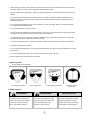
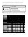
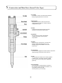
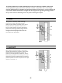
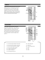
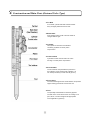
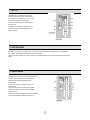
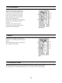
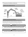
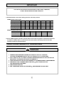
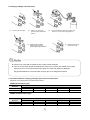
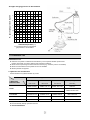
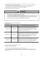
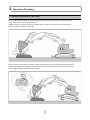
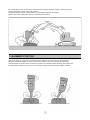
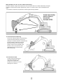
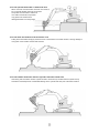
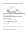
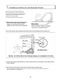
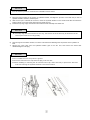
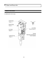
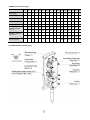
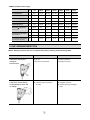
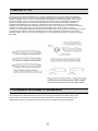
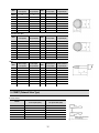
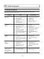
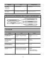
OPERATIONAL MANUAL
CM10
CM20
CM30
CM40/40BL
CM70
CM100
CM150
!
CM160
CM170
CM200
CM230
CM250
CM350
CM360
CM400
CM450
CM500
CM550
CM600
"!
OPERATIONAL MANUAL
CM10
CM20
CM30
CM40/40BL
CM70
CM100
CM150
CM160
CM170
CM200
CM230
CM250
CM350
CM360
CM400
CM450
CM500
CM550
CM600
COMET
HYDRAULIC BREAKER
OPERATION
MANUAL
&
PART LIST
COMET INC
COMET TECHNOLOGY & ATTACHMENT
!
1. Safety Precautions
! This manual contains safety, operation, and routine maintenance instructions.
It does not contain assembly and disassembly service procedure instructions. If needed,
complete disassembly and assembly instruction are contained in the service manual which
can be ordered from your COMET Hydraulic breaker authorized and certified dealer.
! Please read the following warning.
DANGER
!
SERIOUS INJURY OR DEATH COULD RESULT FROM THE IMPROER REPAIR OR SERVICE OF THIS
BREAKER. REPAIRS AND / OR SERVICE TO THIS BREAKER MUST ONLY BE DONE BY AN
AUTHORIZED AND CERTIFIED DEALER.!
General safety precautions!
! The COMET hydraulic Breaker series CM type will provide safe and dependable service if
operated in accordance with the instructions given in this manual. Read and understand this
manual any decals and tags attached to the breaker before operation. Failure to do so could
result in personal injury or equipment damage.
! Operate the breaker in accordance with all laws and regulations which affect you, your equipment, and the
work site.
! Do not operate the breaker until you have read the carrier equipment manual and thoroughly understand
all safety requirement, operation and maintenance instructions.
! Ensure that all maintenance procedures recommended in this manual are completed before using the
equipment.
! The operator must not operate the breaker or carrier if any person is found within the danger zone where
they may be injured by flying debris or movement of the equipment.
! Know the limitation of your equipment.
! Establish a training program for all operators to ensure safe operation.
! Do not operate the breaker unless thoroughly trained or under the supervision of an instructor.
! Get used to the carrier controls before operating the carrier and the breaker.
! While learning about the breaker and the carrier, please do so at a slow pace. If necessary, set the carrier
mode selector to the slow working position.
! Make sure all control (levers and pedals) are in the neutral position before starting the carrier.
! Before leaving the carrier, always lower the boom and insure the carrier is stable. Never leave the machine
when the engine is running. Always engage the parking breaker locked.
! Stop the engine before attempting to make any repairs, adjustments, or servicing to either the carrier or the
breaker.
! Do not operate the breaker at oil temperature above 175°F/80°C. Operation at higher temperatures can
damage the internal components of the breaker and as well as backhoe/excavator, and will result in low
breaker performance.
! Do not operate the breaker at in the severe conditions, such as, a damage, leaking, improperly adjusted,
or incompletely assembled breaker.
! Do not modify breaker tool in any manner.
! Use only breaker and breaker tools manufactured by Comet only. Using the breaker tool produced by other
manufacturers may damage the equipment and will void the warranty.
! To avoid personal injury or equipment damage, all breaker repair, maintenance and service must only be
performed by authorized and properly trained personnel.
! If you do not understand how to operate your breaker, contact an authorized Comet Dealer for assistance.
! Keep this manual with the breaker.
! Do not operate this equipment if you are taking medication which may affect you mental judgment or physical
performance.
! Do not operate this equipment if you are under the influence of drugs or alcohol.
! Remove breaker from carrier during the transport.
! Warning sticker
- shown smaller then actual size
Use Hearing Protection
Use Eye Protection
Use Breathing Protection
Read the manual
before use
! Safety symbols
DANGER
WARNING
IMPORATNT
!
!
This safety symbol may appear on the
This safety symbol appears in these
This safety symbol appears in these
breaker. It is used to alert the operator of
instructions to identify an action that
instructions to identify an action or
an action that could place him/her or
other in a life threatening situation.
could cause bodily injury to the
operator or other personnel.
condition that could result in damage
to the breaker or other equipment.
! Safety symbols are to emphasize all operator, maintenance, and repair action, which, if not strictly followed,
could result in a life-threatening situation, bodily injury or damage to equipment.
! Always observe safety symbols. They are symbols for your safety and for the protection of the tool.
! Greasing sticker
GREASING
1. With breaker mounted on carrier, apply down pressure on tool.
2. Fill cavity with recommended grease.
3. Grease whenever tool looks dry.
4. When installing a new tool, liberally coat the upper 1/3 of the
tool with grease before inserting.
5. Failure to comply with these instruction can result in damage
To the breaker and will void the warranty.
2. Technical Specification (COMET Breaker)
Description
BOX TYPE
Operating
Weight
(Mount Cap
+Rod)
TOP TYPE
SIDE TYPE
Weight of Main Body
Required Oil Folw
Setting pressure
CM10
CM 20
CM30
CM35
CM 40
CM 40BL
CM 55
CM 70
CM100
CM 150
CM 200
kg
102
127
166
205
290
-
433
553
860
1350
1863
lb
225
280
366
452
639
-
954
1219
1896
2976
4107
kg
70
100
160
195
260
-
410
510
820
1310
1862
lb
154
220
353
430
573
-
904
1124
1808
2888
4105
kg
70
100
140
180
250
340
395
473
765
1310
1862
lb
154
220
309
396
551
749
870
1043
1685
2888
3373
kg
51
61
76
116
136
136
190
240
414
498
833
lb
112
134
168
226
300
300
419
529
913
1098
1836
l/min
15~30
20~40
20~50
30~60
30~50
30~50
50~90
45~90
80~110
90~120
130~150
gal/min
4~8
5~10
5~13
8~16
8~16
8~16
16~24
12~24
21~29
24~32
34~40
bar
130
140
150
150
160
160
180
180
210
210
210
psi
1885
2030
2175
2175
2320
2320
2611
2611
3046
3046
3046
bar
90~120
90~120
100~130
100~130
90~130
90~130
120~150
130~150
150~170
150~170
160~180
psi
1305~1740
1305~1740
1305~1740
1450~1885
1305~1885
1305~1885
1740~2176
1885~2176
2176~2465
2176~2465
2321~2611
bpm
800~1400
700~1100
550~950
500~1000
450~750
450~750
400~800
400~800
450~630
400~750
400~800
mm
13
13
13
13
13
13
13
18
18
25
25
inch
1/2”
1/2”
1/2”
1/2”
1/2”
1/2”
1/2”
3/4”
3/4”
1”
1”
Tool Diameter
mm
40
45
53
60
68
68
75
85
100
120
135
Tool Length
mm
400
500
580
600
690
690
750
800
1000
1100
1200
Applicable carrier Weigh
ton
0.5~1.5
0.8~3
1.5~4
3~5.5
4~6
4~6
6~9
6~11
6~11
15~18
18~25
Operating pressure
Impact Rate
Hose Diameter
Description
BOX TYPE
Operating
Weight
(Mount Cap
+Rod)
TOP TYPE
SIDE TYPE
Weight of Main Body
Required Oil Folw
Setting pressure
Operating pressure
Impact Rate
Hose Diameter
CM 200
CM 220
CM 250
CM 330
CM 350
CM 400
CM 450
CM 500
CM 550
CM 600
kg
1863
1843
2018
2298
2490
2742
3180
3012
3980
4100
lb
4107
4063
4449
5066
5490
6045
7011
6640
8775
9039
kg
1862
1802
2000
2270
2498
2753
2980
3030
3820
4000
lb
4105
3973
4409
5005
5507
6069
6570
6680
8422
8819
kg
1862
1530
1690
2144
2340
2375
2980
2650
3725
3909
lb
3373
3366
3726
4727
5159
5236
6570
5842
8212
8618
kg
833
761
946
1128
1082
1325
1412
1453
1726
4720
lb
1836
1678
2086
2487
2385
2921
3113
3203
3805
10406
l/min
130~150
130~150
130~150
150~210
150~190
180~240
190~250
200~260
210~290
250~320
gal/min
34~40
34~40
34~40
40~55
40~50
45~63
50~66
53~69
55~76
66~84
bar
210
210
210
210
230
230
230
230
250
250
psi
3046
3046
3046
3046
3336
3336
3336
3336
3626
3626
bar
160~180
160~180
160~180
160~180
160~180
160~180
160~180
160~180
160~180
170~190
psi
2321~2611
2321~2611
2311~2611
2321~2611
2321~2611
2321~2611
2321~2611
2321~2611
2321~2611
2466~2756
bpm
400~800
400~600
350~550
300~450
350~650
300~450
300~600
250~400
200~350
230~320
mm
25
25
25
25, 32
25
32
32
32
32
32
inch
1”
1”
1”
1”, 1""
1”
1""
1""
1""
1""
1""
Tool Diameter
mm
135
135
140
150
150
155
160
165
175
180
Tool Length
mm
1200
1200
1200
130
1300
1400
1400
1400
1400
1600
Applicable carrier Weigh
ton
18~25
18~25
18~25
25~30
28~35
28~35
35~48
30~45
40~55
45~60
( Specification and features in catalogue are subject to change without prior notice to better improvement in quality.
3. Construction and Main Parts (Inward Valve Type)
! Tie Rod
Front head, cylinder, and back head of breaker
Body are tightly fixed with four tie rods.
! Back Head
Oil pressure inlet and outlet ports and Gas
charging valve are built in it, and the inside is
charged with N2-gas.
! Valve
Cylindrical control valve is built in the valve
housing to control piston reciprocation.
! Cylinder
The cylinder is the heart of the breaker
containing hydraulic circuit for piston
reciprocation.
! Piston
Kinetic energy of the piston is converted into
blowing energy after hitting the tool. The
blowing energy is transmitted to the tool to
break rocks.
! Front Head
The front head supports the whole breaker components.
upper bushing prevents shock from the tool.
! Tool
The specially heat-treated tool is directly applied
to break rocks. It is used as moil point, wedge
point, and flat tool according to the application,
(optional)
! Accumulator
The accumulator compensates the pressure in
the hydraulic circuit and prevents pulsation. It is
not usually necessary to refill.
Use N2-gas only. (In main body)
The relation between the area [A1] affecting the pressure from the upper chamber of the piston
and the [A2] affecting the pressure from the lower chamber of the piston is A1 > A2 and high
pressure always applies to A2. When A1 change from high to low pressure or vice versa, Piston C2
reciprocates. Inside of back head is changed with the high pressure gas and gas energy stored in
the up stroke of the C2 effectively acts on the piston C2 during the impact.
1. POWER
When piston C2 reaches top head center, high
pressure oil from valve high-pressure port B3
applies to upper chamber of the piston A1 to change
the piston stroke from upstroke to impact. At this
time the relation between the area(A3) affecting the
pressure from valve high pressure changes and the
area(A4) of the valve change chamber is A4 > A3.
The high pressure always applies to A4 and valve
C4 remains in the upper position.
2. VALVE SHIFT
When cylinder low pressure port B1 is connected to
cylinder change port B2, the pressure in valve change
port B4 lowers. As force acting port C4 is the only
pressure in valve high pressure chamber A3, valve C4
starts lowering. During the valve lowering stroke, valve
high pressure port B3 is closed and valve low pressure
port B5 is opened to the lower the pressure in the upper
chamber of the position A1.
3. IMPACT
When piston C2 reaches impact point, kinetic energy
obtained by piston C2 during the impact stroke is
transmitted to the tool C3 for the impact energy
required to break. At this time, as high pressure
applies only to the lower chamber of the piston A2,
piston C2 starts reversing. Further, as high pressure
applies only to the valve high pressure chamber A3,
valve C4 is remaining in the lower position.
4. UPSTROKE
When cylinder change port B2 is connected to
cylinder lower pressure port B1, high pressure oil
applies to low pressure outlet port valve C4 time
valve low pressure port A1 this time valve low
pressure port B5 is closed and valve high pressure
B3 is opened the upper chamber of the piston A1
to rise the pressure in the lower chamber of the
piston A1.
A1 : Area of the upper chamber of the piston
B4 : Valve change port
A2 : Area of the lower chamber of the piston
C1 : Power cell
A3 : Area of valve high pressure chamber
B5 : Valve low pressure port
A4 : Area of valve change chamber
C2 : Piston
B1 : Cylinder low pressure port
C3 : Tool
B2 : Cylinder change port
C4 : Valve
B3 : Valve high pressure port
!
4. Construction and Main Parts (Outward Valve Type)
! Tie Rod
Front head, cylinder and back head of breaker
body are tightly fixed with four tie rods.
! Back Head
Gas charging valve is built in and the inside is
changed with N2 gas.
! Cylinder
The cylinder is the heart of the breaker
containing hydraulic circuit for piston
reciprocation.
! Control Valve
Cylindrical control valve is built in the valve
housing to control piston reciprocation.
! Accumulator
The accumulator compensates the pressure in
the hydraulic circuit and prevents pulsation. It is
not usually necessary to refill. Use N2 gas only.
! Front Head
The front head supports the whole breaker components.
Upper bushing prevents shock from the tool.
! Tool
The specially heat-treated tool is directly applied
to break rocks. It has various forms of a wedge, moil
point, blunt, cone and wedge chisel appropriate
to the application. (optional)
1. SET UP
Chambers C3, C2 always maintain low
pressure because they are connected to
the output line. Chambers V3, V1, C1, and
accumulator always maintain high
pressure because they are connected to
the input line.
Chamber V2 pressure is changed to low
pressure or high pressure depending on
piston position.
2. PISTON RAISE
Oil enters into “IN” port, and begins to accumulate force to raise piston; hydraulic force is applied on
A1 of piston lower flange and piston begins to be raised.
When the piston begins to be raised, oil from C4 chamber returns to the output line through the control
valve.
3. VALVE RAISE
When piston be raised to around upper limits, A1
of piston lower flange reaches chamber C2,
and the back head nitrogen(N2) gas is
compressed.
At this time, oil from chamber C2 goes to
chamber V2.
A3 area is larger than A4 area, but applied
pressure of area A3 is the same as applied
pressure of A4.
Therefore, the valve begins to be raised, because
of the area difference between A4 and A3.
4. PISTON DESCENT
When the valve reaches the upper limits,
chamber C4 becomes high pressure area
because oil from the working pump goes
to chamber C2 through the control valve
holes. A2 area is larger than A1 area, but
pressure applied to A4 area is the same
as them pressure applied to A1.
Therefore, the piston begins to be descended,
because of the area difference between
A2 and A1.
At this time, piston descent speed is
accelerated by compressed nitrogen (N2)
gas pressure and piston weight.
5. IMPACT
Chamber V2 is changed in low pressure as
chamber C2 is connected with C3 during piston
descent.
But V3 is always high pressure. Therefore, the
valve begins to be descended.
6. CONTINUOUS STRIKE
After the piston strikes the top of the tool, the status of all circuits is changed to “Piston Raising”.
The piston begins to be raised via status flowing into “IN” port and the cycle is repeated again.
5. Preparation for Installation and Operation
.
!
1. GENERAL VIEW OF BREAKER INSTALLED
2. HYDRAULIC PIPE LINES FOR EXCLUSIVE USE
Operation of the hydraulic breaker requires installation of hydraulic pipe lines for exclusive use of the
hydraulic breaker. As hydraulic pipe lines vary depending on base machines, our service engineer must
first check hydraulic pressure, oil capacity, pressure loss and other conditions of the base machine before
installing hydraulic pipe lines. Use only genuine parts in case of replacement because hydraulic pipe lines
(hoses, pipes and fittings) are made of materials carefully selected in consideration of durability.
!
WARNING
THE HYDRAULIC SYSTEM TO THE BASE MACHINE MUST BE CHECKED BY AN AUTHORZED
TORPEDO SERVICE ENGINEER BEFORE FIRST USE AND AFTER ANY MODIFICATIONS
!
WARNING
MAKE SURE THAT THE BREAKER VALVE OF HYDRAULIC SYSTEM IS PROPERLY SET
3. CHECKING – BEFORE INSTALLING INSTRUCTIONS
WARNING!
1. CHECK THE “SPECIFICATIONS” SECTION OF THIS MANUAL TO DETERMINE CORRECT
BACKHOE AND EXCAVATOR SIZES, HYDRAULIC PRESSURE, AND HYDRAULIC FLOW
REQUIREMENTS.
2. IF HYDRAULIC PRESSURE, HYDRAULIC FLOW ARE EXCEEDED,
THE BREAKER WATTANTY IS NOT APPLIED.
3. CHECK THE NITROGEN GAS – BACK HEAD AND ACCUMULATOR.
4. BE SURE THE FLUID IN THE HYDRAULIC SYSTEM IS CLEAN.
5. CHECK THE HYDRAULIC FILTER, REPLACE THE FILTER IF DIRTY OR DETERIORATE
6. HOSE AND PIPING MUST BE FLUSHING.
7. THE CONTAMINATED PART MUST BE CLEANED WITHOUT DELAY.
HYDRAULIC OIL OR LIGHT OIL IS HIGHLY RECOMMENDED.
IMPORTANT!
THE CIRCUIT RELIEF SETTING PRESSURE IS NOT FIXED. HOWEVER,
IT WILL BE ADJUSTED BY PUMP CAPACITY
! Recommended circuit relief setting pressure and back pressure
COMET (Inward Valve Type)
CM 10
CM 20
CM 30
CM 35
CM40/40BL
CM 55
CM 70
Relief Setting Pressure
*/+
130
140
150
150
160
170
180
Back Pressure [MAX]
*/+
14~16
14~16
14~16
14~16
16~17
16~17
16~17
CM 100
CM 220
CM 250
CM 330
CM 400
CM 500
CM 550
Relief Setting Pressure
*/+
190
210
220
230
240
250
250
Back Pressure [MAX]
*/+
16~18
16~18
16~18
16~18
16~18
16~18
16~18
COMET (Outward Valve Type)
CM 150
CM 200
CM 350
CM 450
CM 600
Relief Setting Pressure
*/+
210
210
230
230
250
Back Pressure [MAX]
*/+
6.3~7
6.3~7
6.3~7
9~10
16~18
! Since COMET hydraulic breaker operates with various kinds of hydraulic construction machines,
it should be installed after our serviceman has carried out the necessary check on the base
machine to utilize its full performance.
4. INSPECTION AND CHARGING OF N GAS IN BACK HEAD
WARNING!
1. CHARGING GAS PRESSURE CHANGES ACCORDING TO THE TOOL CONDITION.
LAY DOWN THE BREAKER AND LET THE TOOL EXTEND FULLY TO CHARGE GAS.
2. STAY CLEAR OF THE TOOL WHILE CHARGING THE BREAKER WITH GAS. THE TOOL MAY BE
IMPACTED BY THE PISTON AND FORCED OUT ABRUPTLY.
3. TAKE CARE WHEN THE TIE RODS ARE CHANGED OR THE BREAKER BODY IS DISASSEMBLED.
4. USE SPECIAL CARE TO HANDLE AND STORE THE N)GAS CYLINDER AS IT IS A
HIGH-PRESSURIZED CONTAINER.
5. USE NITROGEN GAS ONLY
6. SEE “CONVERSION TABLE FOR CHARGING N)GAS PRESSURE TO BACK HEAD”
! Charging of N2gas into back head
(1)
Remove gas valve plug
(2)
Insert 3-way valve with
pressure gauge assembled
(Note. 1)
(3)
If gas is insufficient, adjust to specified valve
as shown in the previous page (Note. 2)
(4) Adjust the pressure slowly,
decreasing it by using the
pressure gauge if gas is sufficient
!
(5) Tighten gas valve plug
(Do not cut O-ring)
Note
! Insert 3-way valve after its handle is fully turned counterclockwise.
! Turn the 3-way valve handle clockwise slowly. Stop turning it when the needle of the gauge
starts to move. If it is turned clockwise too tightly, the valve may easily be damaged.
Pay special attention to ensure that the nitrogen gas is not charged excessively.!
! Conversion table for charging nitrogen gas pressure to back head
(Depends on the temperature of the back head surface)
COMET(Inward Valve Type)
Back head gas
Pressure
kg/㎠
psi
0 / 32
15.5
220
10 / 50
15.9
226
Ambient Temperature( ⁄ )
20 / 68
30 / 88
16.3
16.8
231
238
40 / 104
17.3
246
10 / 50
6.0
85
Ambient Temperature( ⁄ )
20 / 68
30 / 88
6.2
6.4
88
91
40 / 104
6.6
94
COMET (Outward Valve Type)
Back head gas
Pressure
kg/㎠
psi
0 / 32
5.8
83
5. INSPECTION AND CHARGING OF N GAS IN ACCUMULATOR
WARNING!
! USE SPECIAL CARE TO HANDLE AND STORE THE N2 GAS CYLINDER AS IT IS A
HIGH-PRESSURIZED CONTAINER.
! USE NITROGEN GAS ONLY.
! SEE “CONVERSION TABLE FOR CHARGING N2 GAS PRESSURE TO ACCUMULATOR”
! STANDARD ACCUMULATOR GAS PRESSURE 55kg/cm!/ 780psi, AT 20 /68
AMBIENT
TEMPERATURE, DO NOT OVER PRESSURIZE ACCUMULATOR.
Cautions
!
for charging N䈻gas to the accumulator
! Be sure to use the 3-way valve assembly for charging the N2gas.
If charging gas leaks directly from the cylinder, the diaphragm may be broken off.
! If charging for handing N2gas to only the accumulator, make sure that the accumulator
body and cover are tightened fully.
Make sure the cap and valve of the 3-way valve assembly are fully tightened.
Remove the cap from the accumulator and tighten the charging valve fully.
Check if O-rings are installed to the bushing. Remove the plug and screw in the bushing.
Install the bushing to the 3-way valve assembly.
Loosen the charging valve gradually. The charging pressure is indicated on the pressure gauge.
Close the valve clockwise when the gas pressure is normal. When the gas pressure is higher, repeat
loosening and tightening the valve assembly. The pressure is lowered gradually.
! Loosen the valve of the 3-way valve assembly to discharge the N2gas in the 3-way valve assembly.
! Remove the 3-way valve assembly and tighten the plug and cap.
!
!
!
!
!
!
! Charging of N2 gas into accumulator
! Connect the charging hose to N2gas cylinder after screwing the valve adapter on to adapter,
nut and installing to the N2gas cylinder.
! Connect the 3-way valve assembly to the charging hose after unscrewing the cap on the 3-way valve
assembly.
! Remove the cap from the accumulator and tighten the charging valve fully.
! Check if Orings are installed to the bushing. Remove the plug and screw the bushing.
! Loosen the accumulator charging valve after checking if bushing is installed to the 3-way valve assembly.
! Turn the handle of the N2gas cylinder counter clockwise slowly to charge the gas.
! Charge the gas in accordance with the conversion table for charging N2gas pressure to accumulator.
! Turn the handle of the N2gas cylinder clockwise to close the cock.
! Close the accumulator charging valve.
! Loosen the valve of the 3-way valve assembly to discharge the N2gas remaining in the charging hose.
! Remove the charging hose, 3-way valve assembly and bushing and tighten the plug and cap.
! Conversion table for charging nitrogen gas pressure to accumulator.
COMET CM Series
Accumulator gas
Pressure
0 / 32
10 / 32
Ambient Temperature(C°⁄F°)
20 / 68
30 / 86
40 / 104
kg/㎠
50
52
55
58
61
psi
711
739
780
824
867
! Acc sticker[A] symbol
- Appears on the accumulator body
PRESSURIZED CONTAINER!
DISCHARGE PRIOR TO DISASSEMBLY. DO NOT OPEN
WITHOUT READING THE OPERATION MANUAL OR
CONSULTING THE AUTHORIZED SERVICE PERSONNEL!
N' gas charging pressure (kg/cm!)
! N2gas charging pressure to Accumulator
!""
#"
$"
%"
&"
"
&"
%"
$"
#"
Ambient temperature (()
! Conversion table for charging N2
gas pressure to accumulator
6. HYDRAULIC OIL
! Selection of oil
! Selection of hydraulic oil determines the efficiency of the hydraulic breaker performance.
Please consult with our service station under following conditions.
! When used in special regions where climate is severe (e.g. extremely cold or hot weather)
! When recommended Comet hydraulic oil are not available.
! When hydraulic oil supplied
! Hydraulic Oils and Greases
Recommended for Hydraulic Breaker by Comet!
LUBE & SPEC
LUBRICANTS
MANUFACTURE
Hydraulic Oil
Grease
Summer
Winter
All Season
(MOS₂)
ISO VG 46
ISO VG 32
ISO VG 46
NLGI No₂
MOBIL DTE25
MOBIL DTE 24
MOBIL DTE 15M
MOBIL GREASE
SPECIAL
MOBIL
MOBIL SHC 525
MOBIL EAL SYNDRAULIC 46
LG-CALTEX
BP
SHELL
RANDO HD 46
RANDO HD 32
RANDO HD CZ
MOLYTEX EP2
ENERGOL HP 46
ENERGOL HP 32
ENERGOL HP 46
-
TELLUS 46
TELLUS 32
TELLUS T 46
RETINAX HDX-2
! Synthetic lubricant
! Environmentally friendly synthetic lubricant! !
! Oil Contamination!
MOBILTH SHC 220
! Contaminated oil results in malfunctions of the breaker as well as the base machine and cause damage
to parts. Pay special attention to oil contamination.
Contaminated oil should be changed without any delay. When changing oil, thoroughly wash oil tank,
cylinder and pipes. Cleaning or replacing oil filter also requires check for oil contamination.
! Replacement of filter : after first 50 hours and every 100 hours thereafter
! Replacement of hydraulic oil : every 500 hours
!
WARNING!
! HYDRAULIC OIL TEMPERATURE AND VISCOSITY
Do not operate the hydraulic breaker at oil temperatures from 20°C/ 68°F to 80°C / 176°F.
Operation at higher temperatures can damage the internal components of the breaker
and excavator, there will result in reduced breaker performance.
!
! Criteria of oil contamination and malfunction
(General Analysis)
Analysis Item
Criteria
Causes and Effects when exceeds the criteria
Within ,10%
40°C cSt
Adhesiveness rarely decreases solely because of hydraulic oil.
Entry of different kind of oil may reduce the adhesiveness which
contributes to rising oil temperature, wear and stretch of bearings
and gears and malfunction of hydraulic oil.
Oxidizing Level
Less than 0.3
(mg KOH/g)
Use of a lubricating oil in a long period of time of under high temp of
a lubricating (higher than 60°C) will oxidize it. Oxidizing level rises as
oxidization proceeds. Sludge will be produced during the process.
Leading to unsatisfactory operation of the breaker, erosion of
metals or obsolescence of seal materials.
Moisture
Less than 0.1
(%)
Moisture causes rust, wear and scratch. Moisture of 1.3% gathers
a considerable amount of rust. And considerable a mount of rust
moisture of 0.5% or more will cause damage to the machine.
Adhesiveness
! Criteria of malfunction by hydraulic oil color
(Simple discrimination by ASTM color)
Hydraulic oil turns black as the breaker fails to display best performance.
The old oil is assumed to be contaminated when there is a visual difference between the old and new oil color
and functions begin to deteriorate when hydraulic oil turns darker than the new oil color (ASTM number) by
more than two.
!
6. Operation (Breaking)
1. PROPER POSITION OF THE TOOL
Proper position must be applied for an effective use of breaking force. When position is incorrect, blowing
energy of the piston is too weak to break rocks.
Instead, blowing force applies shocks to the breaker body, breaker, arm, and boom of the base machine,
thereby resulting in damage to those parts.
On the contrary, when position is excessive enough to break rocks with front of the base machine raised, the
machine may suddenly tilt forward the moment rocks are broken then the breaker body or the end of bracket
may violently hit against rocks and result in damage.
It is undesirable to carry out hammering under the below condition, because vibrations during hammering
may be transmitted to tracks of the base machine.
During hammering, however, proper position must be always applied to the breaker.
Special care must be taken not to hammer under abnormal condition.
2. ALIGNMENT OF THE TOOL
Apply same direction of boom force in line with the tool and place the tool in the rock with hammering
surface as vertical as possible. If hammering surface is oblique, the tool may slip during hammering.
This causes the tool to seize and to be broken and piston to be damaged. When breaking, fully stabilize the
tool first and then select the point of a rock on which hammering can be performed in a stable condition.
3. OPERATION PRECAUTIONS
IMPORTANT!
! APPLY DOWN FORCE TO THE BOOM DIPPER UNTIL THE FRONT OF THE BACKHOE AND
CARRIER IS ARISED OFF THE GROUND.
- THE BREAKER IS MORE EFFICIENT WHEN ADEQUATE DOWN FORCE IS APPLIED.
IMPORTANT!
! RELOCATE THE BREAKER OFTEN
- THE BREAKER TOOL SHOULD BE MOVED TO A NEW LOCATION OF THE WORK EACH TIME
THE TOOL PENETRATES BUT DOSE NOT CRACK THE MATERIAL
IMPORTANT!
! DO NOT BREAK CONTINOUSLY IN ONE PLACE
- CONTINUOUS PENETRATION IN THE SAME AREA FOR LENGTHILY PERIODS WILL
CREATE
EXCESSIVE TEMPERATURES AT THE END OF TOOL RESULTING IN LOSS OF TEMPER
[HARDNESS] OF THE BIT AND CAUSING MUSHROOMING OF THE TIP OF THE BIT,
AND MAY LEAD TO FAILURE OF THE BIT.
IMPORTANT!
! DO NOT PRY WITH THE BIT AND BREAKER.
IMPORTANT!
! THE CONTAMINAED PART MUST BE CLEANED WITH NO DELAY.
HYDRAULIC OIL OR LIGHT OIL IS HIGHLY RECOMMENDED.
Stop operation as soon as hose vibrate excessively.
Excessive vibration of high and low-pressure hoses of breaker calls for an instant disassembly and repair.
Contact the nearest service station appointed by Comet. For caution’s sake, check oil leakage at back
head.
- The operator is required to pay attention to following points during operation.
! Avoid all blank hammering.
As soon as rocks are broken, stop hammering.
Continuous blank hammering will not only
damage front head and loosen and break bolts,
but also adversely affect base machine.
Blank hammering occurs when proper
position of the tool is not applied to the
breaker or the tool is used as a lever.
(Hammering sound changes during
blank hammering)
! Do not move rocks.
Avoid moving rocks with side of
the bracket, because it is the
major factor to break bolts
installed on the bracket, tool and
damage boom and arm.
Do not use tool as a lever.
When breaking rocks by using tool as a lever, bolts and tool may be broken too.
! Do not continue to hammer for more than one minute.
When rocks are not broken after more than one minute’s hammering at the same point, change the place
to be hammed. Extended hammering at the same place causes the tool to wear out excessively.
! On a hard and large rock, start breaking at start breaking from the edge.
Even a hard and big rock can be easily broken
when hammering begins at a crack or an edge.
! Operate breaker at proper engine speed.
Break rocks at the specified engine speed.
Raising engine speed more than necessary
does not strengthen hammering force but
increase oil temperature to the detriment of
pistons and valves.
! Do not operate the breaker in water and mud.
When rocks are not broken after more than one minute’s,
Do not operate breaker when all components
except tool are immersed in water and
mud. Piston and similar components
may gather rust and become a
damaged breaker at an early stage.
! Do not allow the breaker to fall to break a rock.
Falling down the breaker will apply excessive force to the breaker or the base machine, causing damage to
many parts of the breaker and the base machine.
! Do not hammer with base machine cylinders moved to stroke end.
Hammering with each base machine cylinder moved to stroke end (a condition that the cylinder is fully
extended or retracted) will do considerable damage to the cylinder and each part of the base machine.
! Do not lift things with the breaker.
Lifting materials by hanging wire in the bracket or tool not only causes damage to the breaker but also is
very dangerous when operating.
! Warm up base machine engine prior to operation.
Especially in winter, the base machine engine should be warmed up for five to ten minutes 30°C~40°C
(86°F~105°F) before breaker operation. Follow the instruction book for base machine to warm up the
engine.
! Do not touch tool for breaker working
While the breaker is working, high temperature of the tool will be generated.
! When operating the breaker, you must use ear and body protection
You must use ear and breathing protection when the breaker is operating.
! Accumulator type danger
Attention to pressurized container! Do not open without reading the manual or consulting with the
authorized service personal!
! Greasing
With breaker mounted on carrier, Apply down pressure on tool, and fill cavity with recommended grease
through the grease nipple.
! Always wear eye protection when.
Stop pin is being removed it in and out with a punch and hammer.
7. Installation and Removal of the Hydraulic Breaker
When the bucket and breaker operation are
performed alternately, the bucket and breaker
can be easily exchanged by the hydraulic hoses
and two pins. There is, however, a risk of the
hydraulic circuit contamination.
Accordingly, install and remove as follows.
! Move the base machine to stable ground
free from mud, dust, and dirt. Stop the
engine, turn off the main switch and
deflate air from oil tank if it is pressurized.
! Turn 90° the stop valve installed to the end of arm to prevent hydraulic form flowing out.
! Loosen hose plug on the breaker arm. Collect small amount of oil flowing out at this time and put
into a container.
! Be careful to prevent mud or dust from entering oil hoses and pipe lines.
Plug oil hoses with hose plug and pipe lines with union caps. Bind high and low-pressure hoses with a
wire to prevent them from getting mud.
! To remove the breaker, pull out pins in the bucket link and arm.
When leaving the breaker outdoor, set the breaker on wood blocks and cover with sheets.
! When leaving the breaker removed for a long period of time.
- Clean exterior of the breaker.
- Remove tool from the front head and spray with rust preventive oil.
Bleed N2-gas from the back head before pushing piston into cylinder.
- Apply grease to each part of the breaker and then install tool again.
! To install the hydraulic breaker, reverse the fore mentioned removal procedures.
The bucket operation easily contaminates the end part of hoses and pipe lines. The contaminated part
must be cleaned with no delay. Hydraulic oil is highly recommendable.
CAUTION
!
!
! Never insert your hand or fingers into the pin hole
WARINING
!
! While aligning the arm hole, or moving the bucket, make sure that there are no person
In the vicinity of arm or bucket of base machine.
! It is dangerous to move the base machine suddenly during installation.
! Wear the safety shoes to protect feet.
NOTICE
!
! Be careful so that dust may not enter the hydraulic breaker and base machine.
! Install or remove the hydraulic breaker on horizontal ground without mud or dust.
1)
Set the hydraulic breaker on horizontal ground.
2)
Remove the bucket from the base machine after disassembling the two pins.
NOTICE
!
! If the bucket cylinder is retracted, the installation will be easier.
3)
4)
5)
Move the base machine in the vicinity of hydraulic breaker, and align the pin hole of arm with the pin hole of
hydraulic breaker, and then, insert the pins.
After the arm pin is inserted, lift the boom, resert the hydraulic breaker on the wood blocks like as Extend the
bucket cylinder, fit it to the bucket link’s hole and insert the pins.
Install the stop rings, align the bolt holes and insert the bolts. Mutually lock double nut.
NOTICE
!
! If the stop rings are secured with one nut only, the service life of the bolt may be shortened or the
bolt may be loosened our very quickly.
6)
7)
Stop the engine of the base machine, tun off the main switch and discharge the air pressure in the hydraulic oil
tank.
Remove the union caps from the hydraulic breaker pipe of the arm end, and connect the hoses after
disassembling the hose plug.
NOTICE
! Do not allow the oil to drop onto the ground.
! Store the removed union cap and hose plug in the tool box.
! When installing or removing the oil hose and union cap, clean them fully to prevent the dust and
mud from entering the hydraulic breaker or the base machine.
!
CAUTION
!
! Personal
Injury can result from dropping pins during removal.
!
WARNING
!
!
! Wear safety shoes to protect feet.
1)
2)
Set the hydraulic breaker on clean and horizontal ground.
Lock the packing brake of base machine.
Stop the engine.
3)
4)
Turn stop valve to “OFF” position.
Disconnect hoses from stop valves. Ensure no leakage occurs from hoses and stop valves.
5)
Apply union cap and plug to hose ends fittings to prevent.
6)
7)
Remove pins fixing fasteners.
Remove pins.
8)
When pins have been withdrawn, move operating joystick slightly, to take weight off remaining link
pin.
Lift arm away from hydraulic breaker so that hydraulic breaker can be carried away, or another
attachment mounted on base machine.
9)
NOTICE
! Cover the hydraulic breaker already removed with sheet, and then store it in doors.
!
8. Repair and Inspection
1. INSPECTION POINTS
! COMET (Inward Valve Type)
COMET (Inward Valve Type)
Unit
CM 10
CM 20
Tie rod fixing torque
A
Kg.m
30
35
40
40
40
100
100
150
250
250!
260
260
260
350
Accumulator fixing torque
B
Kg.m
-
-
-
-
-
-
-
-
-
60~65
60~65
60~65
60~65
60~65
Accumulator plug fixing torque
C
Kg.m
-
-
-
-
-
-
-
-
-
8~12
8~12
8~12
8~12
8~12
Side bolt fixing torque
D
Kg.m
50
60
80
90
100
145
145
145
250
250
250
250
250
250
Socket bolt fixing torque
H
Kg.m
-
-
-
-
-
-
-
-
-
30~40
30~40
30~40
30~40
30~40
-
Kg/cm#
15
15
16.5
16.5
16.5
16.5
16.5
16.5
16.5
16.5
16.5
16.5
16.5
16.5
-
psi
213
213
235
235
235
235
235
235
235
235
235
235
235
235
-
Kg/cm#
-
-
-
-
-
-
-
-
-
58~62
58~62
58~62
58~62
58~62
-
psi
-
-
-
-
-
-
-
-
-
767782
767782
767782
824~
896
824~
896
K
-
-
-
-
-
-
-
-
-
Back head N)gas pressure
(at 20°C-68°F)
Accumulator N)gas pressure
(at 20°C-68°F)
Valve Adjuster terming position
(O turning when fully closed)
! COMET (Outward Valve Type)
CM 30 CM 35
CM40
CM 55 CM 70 CM100 CM220 CM250 CM330 CM400 CM500 CM550
CM40BL
Part
2.5~3.0 2.5~3.0 2.5~3.0 2.5~3.0 2.5~3.0 2.5~3.0
COMET (Outward Valve Type)
Part
Unit
CM 150
CM 200
CM 350
CM 450
CM 600
Inspection
interval
Tie rod fixing torque
A
Kg.m
150~170
240~250
270~370
270~330
350~400
Every Week
Accumulator fixing torque
B
Kg.m
60~65
50~65
60~65
60~65
60~65
Every Week
Accumulator plug fixing torque
C
Kg.m
8~12
8~12
8~12
8~12
8~12
Every Week
Socket bolt fixing torque
D
Kg.m
20~25
30~40
30~40
40~45
40~50
Every Week
Side bolt fixing torque
E
Kg.m
200~220
250~270
250~270
320~350
320~400
Every Week
-
Kg/cm#
6~7
6~7
6~7
10~11
16~18
Every Week
-
psi
85~99
85~99
85~99
128~142
227~256
Every Week
-
Kg/cm#
54~55
54~55
54~55
58~63
58~63
Every Week
-
psi
767~782
767~782
767~782
824~896
824~896
Every Week
H
-
2.5~3.0
2.5~3.0
2.5~3.0
2.5~3.0
3.75~4.25
Every Week
Back head N)gas pressure
(at 20°C-68°F)
Accumulator N)gas pressure
(at 20°C-68°F)
Valve Adjuster terming position
(O turning when fully closed)
2. DAILY BREAKER INSPECTION
Before starting operation, be sure to inspect the breaker referring to the following table.
Inspection Item
Looseness, missing and
damage to
bolts and nuts
Looseness, of hose fittings,
visible damage to hoses and
oil leakage
Inspection Point
! Tie rod
! Bracket mounting bolts
! Hydraulic pipes for breaker oil hoses
Remedy
! Check looseness
! Retighten securely
! Retighten securely.
! Replace seriously damaged
parts.
Inspection Item
Abnormal
oil leakage
Inspection Point
! Connections of back head
and cylinder
Clearance between front
head & tool (*But small
leakage is normal from
front-head)
Remedy
! Consult with COMET
service station for further
inspection.
Abnormal
wear and
cracks on
tool
! Tool
! Deformed, burred and worn
out tool should be repaired.
! Excessively worn tool needs
to be replaced.
Greasing
! Grease at start and every 2
or 3 hours using head grease
pump.
! Pumping;5~10 times
(Greasing position and
method shown at left.)
! When greasing, press the
tool against on the ground.
(See right fig)
! Grease front head.
Level and
contamination of
hydraulic oil
! Conditions of hydraulic oil
! Contamination of hydraulic oil
caries with operating
conditions, The oil color tells
the level of contamination.
! Criteria for judging
contamination is specifically
set by COMET
! When contamination is
excessive, drain and flush the
hydraulic oil tank and fill it
with new oil.
Missing rubber
plugs and snap
rings
! Rubber plugs.
! Snap rings
! A seriously damaged part
must be replaced.
(Silence type breaker)
Clearance of wear plate, guide
plate, cushion etc"
Check every 3 month, if the
wear-plate, guide-plate,
cushions are good or not
If it is worn too mush or
damaged, replace the parts.
3. REGUALR BREAKER INSPECTION AND MAINTENANCE
Regular inspection is essential for keeping hydraulic breaker operating in the best condition consult with
the Comet service station for regular inspection and maintenance. Customers are recommended to
contact the service station for inspection within six months after delivery.
4. REPLACEMENT OF TOOL
Tool is deformed of burrs produced in a long-term use.
When a tool tip is worn out, tool is liable to slip. Then,
sharpen the tool tip. Grinding the tool tip many times to
sharpen the edge, however, it will make a heat-treated
hardened surface layer disappear and it will wear out
the tool rapidly. In this case, replace with a new tool.
If a gap between tool and front cover ring becomes large,
piston fails to fit in tool resulting in damage. When the gap
is found in over 9mm, replace thrust ring together
with the tool.
! Replacement Order
!
Remove steel plug (or snap-ring) and tool pin in order with a
330mm-long steel bar. When reassembling, align groove in
tool to tool pin hole and insert tool pin.
!
Reverse disassembly procedures to install a replacement
tool. Before installing a new tool, check each part for wear,
breakage, scores, etc$ Remove burrs and swellings on
each tool pin, apply a coat of grease to the movable and
frictional areas of the tool pin and tool, and finally install tool.
Excessively, deformed tool pins will make difficult replacement
of tool. Therefore, tool pins are required to be checked every
100 to 150 hours of operation.
!
If replacement tool is not a genuine part, we do NOT
WARRANTY the performance of other parts of the breaker.
5. BREAKAGE OF TOOL
The service life of various tool depends on the manner of handling them. The tool can sufficiently withstand
the vertically acting load, but it is weak to the perpendicularly acting load. Especially, the tool is affected by the
negative conditions, such as, force by craning operation, tilted blowing, wrenching, idle strokes, etc. its service
life become shorter. There are several ways of breakage of tool. Each cause of breakage can be inferred by
observing breakage sections. Further the breakage case which is not caused by low-quality materials or
insufficient heat-treatment but by wrong way of handling, which the manufacturer is not responsible for the
breakage. (See below figure) The breakage section has the origin on the outer surface, a narrow area of fatigue
breakage and a wide area of rough grey area and final breakage part has the share-lip form. Such an
undulation on the breakage section and its inclination to the right and left can be proved that the breakage is caused
by excessive force which exceeds the toughness of the tool. Such a breakage is supposed to occur owing to
careless handling of the tool. To avoid such a breakage, more carefulness and attention are required in handling
the breaker.
6. DISASSEMBLEY AND ASSEMBLY OF BREAKER BODY
Since breaker body is manufactured by stare of-the art processing techniques and consists of high-quality
hydraulic parts, it is dangerous to disassemble breaker at a workshop. Contact our service station when
disassembly is called for, otherwise quality and performance of the breaker cannot be guaranteed.
9. Wear Tolerance
1. COMET (Inward Valve Type)
!
Front Cover
Inside diameter A
as new part (mm)
40
45
53
60.5
68
75
85
100
135
140
150
155
165
175
Inside diameter
as reject limit (mm)
42
47
55
63.5
71
79
89
105
140
145
155
160
170
180
Model
Inside diameter A
as new part (mm)
Inside diameter
as reject limit (mm)
CM 10
CM 20
CM 30
CM 35
CM 40/40BL
CM 55
CM 70
CM 100
CM 220
CM 250
CM 330
CM 400
CM 500
CM 550
40
45
53
60.5
68
75
85
100
135
140
150
155
165
175
42
47
55
62.5
71
79
89
105
140
145
155
160
170
180
Model
Size A
as new part (mm)
Size B
as reject limit (mm)
CM 10
CM 20
CM 30
CM 35
CM 40/40BL
CM 55
CM 70
CM 100
CM 220
CM 250
CM 330
CM 400
CM 500
CM 550
20
24
24
36
30
30
54
60
80
89
93.5
97
97
99.5
18
22
22
34
28
28
51
57
77
86
90.5
94
94
96.5
Model
CM 10
CM 20
CM 30
CM 35
CM 40/40BL
CM 55
CM 70
CM 100
CM 220
CM 250
CM 330
CM 400
CM 500
CM 550
!
!
Thrust Bush
Tool Pin
Outside diameter A
Outside diameter B
as new prat(mm)
as reject limit(mm)!
CM 10
10
8
CM 20
10
8
CM 30
10
8
CM 35
13
11
CM40/40BL
16
Model
Outside diameter A
Outside diameter B
as new prat(mm)
as reject limit(mm)
CM220
20
18
CM250
20
18
14
CM330
20
18
Model
CM 55
16
14
CM400
17.5
15.5
CM 70
17.5
15.5
CM500
17.5
15.5
CM 100
17.5
15.5
CM550
26
24
Outside diameter A
Outside diameter B
as new prat(mm)
as reject limit(mm)
Front Cover Pin
Outside diameter A
Outside diameter B
as new prat(mm)
as reject limit(mm)!
CM 10
13
11
CM 20
10
8
CM 30
13
11
CM220
30
28
Model
Model
CM 35
13
11
CM250
30
28
CM40/40BL
16
14
CM330
26
24
CM 55
16
14
CM400
26
24
CM 70
20
18
CM500
26
24
CM 100
26
24
CM550
36
34
Effective lengh A
Usable length B
Outside diamete A
Outside diameter B
as new prat(mm)
as reject limit(mm)!
as new prat(mm)
as reject limit(mm)
CM 10
247
130
CM 20
326
223
CM 30
360
245
CM220
772
475
CM 35
374
254
CM250
662
356
CM40/40BL
422
282
CM330
846
536
CM 55
384
229
CM400
883
563
CM 70
474
324
CM500
933
593
CM 100
606
381
CM550
918
578
Tool
Model
Model
2. COMET (Outward Valve Type)
! Front Cover
Inside diameter A
Inside diameter
as new part (mm)
as reject limit (mm)
CM 150
120
126
CM 200
135
141
CM 350
150
158
CM 400
155
163
CM 450
160
168
CM 600
180
188
Model
! Thrust Bush
Model
Inside diameter A
as new part (mm)
Inside diameter
as reject limit (mm)
CM 150
120
126
CM 200
135
141
CM 350
150
158
CM 400
155
163
CM 450
160
168
CM 600
180
188
Model
Size A
as new part (mm)
Size B
as reject limit (mm)
CM 150
70
67
CM 200
80
77
CM 350
89
86
CM 400
100
97
CM 450
100
97
CM 600
120
117
Model
Outside diameter A
as new part (mm)
Outside diameter B
as reject limit (mm)
CM 150
17.5
15.5
CM 200
20
18
CM 350
20
18
CM 400
25
23
CM 450
25
23
CM 600
26
24
Model
Inside diameter A
as new part (mm)
Inside diameter B
as reject limit (mm)
CM 150
26
24
CM 200
30
28
CM 350
30
28
CM 400
36
34
CM 450
36
34
CM 600
36
34
Model
Effective length A
as new part (mm)
Usable length B
as reject limit (mm)
CM 150
700
380
CM 200
765
450
CM 350
780
460
CM 400
825
480
CM 450
825
480
CM 600
914
485
! Tool Pin
! Stop Pin
! Front Cover Pin
! Tool
10. Trouble shooting guide
1. PROBLEMS IN OPERATION
If the breaker does not work or blow frequency and blow power get worse, check the arranging method.
And then inspect according to the following order.
Symptom
No blow out
Cause
1.
2.
3.
4.
5.
6.
Low impact
power
1.
2.
3.
4.
5.
6.
7.
8.
Irregular
impact
1.
2.
3.
Bad tool
1.
2.
movement
3.
4.
Sudden reduction
power and pressure
line vibration
1.
2.
Required action
Excessive back head gas pressure
Stop valve(s) closed
Lack of hydraulic oil
Wrong adjustment of pressure
reducing valve
Faulty hydraulic hose connection
Oil back head infection
1.
2.
3.
4.
5.
Re-adjust nitrogen gas pressure
Open stop valve
Fill hydraulic oil
Tighten or replace
Replace back head o-ring, or
cylinder bush step seal
Line leakage or blockage
Clogged tank return line filter
Lack of hydraulic oil
Hydraulic oil contamination, or heat
deterioration
Poor main pump performance
Back head nitrogen gas low
Low flow rate by mis-adjustment of
flow control pressure reduction valve
Chisel out of range for blowing
position
1.
2.
3.
4.
Check lines
Wash filter, or replace
Fill hydraulic oil
Replace hydraulic oil, rinse tank and
replace hydraulic oil inside lines
Call an authorized service man
Refill nitrogen gas
Re-adjust reduction valve
Rush down chisel by excavator
operation
Low accumulator gas pressure, of
bad accumulator
Bad piston or valve sliding surface
Piston moves down/up to blank blow
hammer chamber
1.
2.
3.
Refill nitrogen gas
Call an authorized service man.
Rush down tool by excavator
operation
Tool diameter incorrect
Tool and pin jammed from tool
retainer pin wear
Jammed lower bush and tool
Deformed tool and piston
contact area
1.
4.
Replace tool with genuine
replacement parts
Smoothen rough surface of tool
Smoothen rough surface of lower
bush interior
Replace tool
Accumulator gas leakage
Accumulator diaphragm damage
1.
2.
Replace o-ring, or refill nitrogen gas
Replace diaphragm
5.
6.
7.
8.
2.
3.
Symptom
Cause
Required action
Oil leakage
between front
head and tool
1. Cylinder seal worn
1. Replace seal
Gas leakage
1. O-ring damage in related parts
1. Replace relevant o-ring
RELATION OF GAS PRESSURE, IMPACT ENERGY AND FREQUENCY
!
!
!
Gas pressure low
Gas pressure
high
Lack of impacting
Power
!
No Breaker
Function
!
Low Blow
Frequency
2. GAS LEAKAGE
Trouble
Cause
Remedy
Gas leakage from the top
of charging valve
! Defective o-ring in charging valve
! Defective or damaged in charging
valve
! Replace
! Repair or replace charging
valve
Gas leakage between
charging valve and
back head
! Defective o-ring in charging valve
! Charging valve loose in back head
! Replace
! Re-tighten
Gas leakage between
cylinder and back head
! Defective o-ring in back head
! Replace
Gas leakage from drain
plug hole
! Defective gas seal in seal retainer
! Defective step seal in seal retainer
! Seizing of piston and seal retainer
! Replace
! Replace
! Repair or replace seal
retainer and piston.(When
repaired replace packing)
3. OIL LEAKAGE
Even if oil is leaking, there is on use to replacing parts at all times. Check the following points listed in the
chart below. The user can check the ( ) marked points before calling the dealer.
Area of oil leakage
A
B
Between the tool and
lower bush
Surface of breaker
Condition
Causes & Remedies
! A large amount of oil is leaking
! Check if it is coming from oil or
grease
Seals damaged
! Oil leaking from the hose &
flange adapter portion
. Loose breaker hoses and bolts
REPLACE
RETIGHTEN
C
Valve housing bolts &
cap bolts
! Oil leakage from reassembly
of valve after overhaul
NORMAL :
During assembly from lubrication
oil & anti-rust oil applied
D
Between main valve &
surface of cylinder
! Oil leakage from reassembly
of breaker after overhaul
NORMAL :
- Clean oil
- Check that seal is damaged
- Loosen bolts
- Replace with new seal
E
Between cylinder and
back head
! Oil leakage
. Loose tie rod nuts
RETIGHTEN
! Oil leaks again
REPLACE
Damaged o-ring
F
Between cylinder and
front head
! Oil is leaking
Loose plugs assembled on the
surface of cylinder
RETIGHTEN
Replace damaged seals
11. Maintenance Intervals
NOTICE
! Before hydraulic breaker operation, be sure to check the following points
! Every 3 hours
- Apply the grease in front head.
- Check hydraulic oil temperature. Piping and hose connections, and working condition.
- Check tightness of fasteners.
! Every 10 hours, or Daily
- If rough skin on the tool and tool pins have found, its must be removed.
- Check the nitrogen gas pressure in back head.
- Retighten the bracket bolts.
! Every 50 hours, or Weekly
- Check the clearance between tool and front cover.
- Check hydraulic hoses
- Retighten the through bolts.
! Every 1000 hours, or Six(6) Months
- Factory inspection by authorized service personnel recommended.
- All hydraulic pipe and hose connections.
- Hose interference from carrier movement.
- Conditions of oil filter. accumulator diaphragm, through bolts and tool pins.
- Check top buffer & base buffer. (Box Type)
- Change wearing plate. (Box Type)
! Every 2000 hours, or Annually
- All hydraulic pipe and hose connections.
- Hose interference with excavator boom.
- Conditions of oil filter, accumulator diaphragm and through bolts.
- All seals & Plugs.
- Conditions of piston, front cover, inner bush.
- Change top buffer & base buffer.
!
12. Moving and lifting
WARNING
!
!
Always use eye-bolts when lifting & moving the hydraulic breaker, after fasten up to bracket. Fasten
The ropes to the shackles(four pleces) and lift the hydraulic breaker up.
Remove the eye-bolts before hydraulic breaker operation.
The hydraulic system to base machine must be checked by an authorized service engineer before
first use and after any modification
13. Storage
When operation is interrupted or after operation
When operation is interrupted or after finishing the work. Move the base on level ground Remove mud from the
Hydraulic breaker and set the hydraulic breaker on wood blocks.
CAUTION
! not touch the tool when hydraulic breaker just stop to work. Because very hot.
! Do
!
- Check whether oil leaks from hydraulic system and whether the tool is damaged.
- If the hydraulic breaker is operated in river. Dry the hydraulic breaker body and apply the grease to the front head.
When hydraulic breaker is not used for a long time 3 weeks more
CAUTION
! If! the following procedures are neglected, the rust is generated in the main body to cause serious
Troubles.
- Discharge the nitrogen gas with the back head and accumulator, and then push the piston to avoid rust into the
cylinder.
- Assemble the tool and store the hydraulic breaker indoors after applying the grease to every part, especially
Internal part, of front head.
!