1
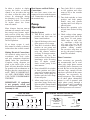
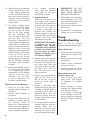
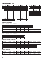
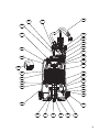
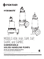
S4M Shown H3H Shown S4HRC Shown MODELS H3H, H4H, S4M, S4P, S4HRC and S4MRC SUBMERSIBLE SOLIDS HANDLING PUMPS INSTALLATION AND SERVICE MANUAL For use with product built with USEM motor. NOTE! To the installer: Please make sure you provide this manual to the owner of the equipment or to the responsible party who maintains the system. Item # E-03-486 | Part # 5625-486-1 | © 2013 Pentair Ltd. | 11/06/13 General Information Attention: This manual contains important information for the safe use of this product. Read this manual completely before using this product and refer to it often for con tin ued safe product use. DO NOT THROW AWAY OR LOSE THIS MAN U AL. Keep it in a safe place so that you may refer to it often. Reasonable care and safe methods should be practiced. Check local codes and requirements before installation. Unpacking Pump: Remove pump from carton. When un pack ing unit, check for concealed damage. Claims for damage must be made at the receiving end through the delivery carrier. Dam age cannot be processed from the factory. WARNING: Before handling these pumps and controls, always disconnect the power first. Do not smoke or use sparkable electrical devices or flames in a septic (gaseous) or possible septic sump. CALIFORNIA PROPOSITION 65 WARNING: This product and related accessories contain chemicals known to the State of California to cause cancer, birth defects or other reproductive harm. Pumps Not Operating or in Storage: Pumps with carbon ceramic seals must have impellers manually rotated (6 revolutions) after setting non-operational for 3 months or longer and prior to electrical start-up. 2 Pumps with tungsten carbide seals must have impellers manually rotated (6 revolutions) after setting non-operational for 3 weeks or longer and prior to electrical start-up. Seal Failure: An electrode is installed in the seal chamber so if any water enters the chamber through the first seal the electrode will be energized and a signal will be transmitted to the sen sing unit at ground surface causing a red light to turn on. The elec trode probe is installed in all units, but the sensing unit is supplied at extra cost and must be ordered. In operation the seal failure unit in di cates only that there is some water in the seal chamber. The pump will con tin ue to operate, but the seal should be checked immediately after failure is indicated. The sensing unit is recommended on all installations as good insurance against motor failure. Pump: The submersible pumps in this manual are supplied for 1 and 3 phase and for 200, 230, 460 or 575 volts. Power cable is supplied with the green wire for ground. Be sure green wire is connected to a good ground such as water pipe or ground stake. Heat Sensors: All motors have heat sensor units embedded in the motor winding to detect ex ces sive heat. The heat sen sors are set to trip at 130°C. The sensors automatically reset when motor cools to safe temperature. The sensors are connected in series with the motor starter coil so that the starter is tripped if heat sensor opens. The motor starter is equipped with overload heaters so all normal overloads are protected by the starter. IMPORTANT: If Hydromatic® electrical starting equipment is not supplied, the heat sensor circuit must be connected in series with the starter coil or warranty is void. Sump Level Control: Sump level is controlled by Hydromatic switch controls. The float is held in position in the sump by a weight attached to the power cord above the float. The cord supports the float and is adjusted for height from the surface. Duplex systems use three controls: one set at turn-off, one set at turn-on for one pump, and one set for turn-on for two pumps. Pumps alternate operation on each successive cycle. Two pumps operate together only if sump level rises to the third or over ride control. The override control also brings on the second pump in case of failure of the first pump. Extra floats with ap propriate controls can be supplied for alarm functions. Triplex systems use four controls: one set at turn-off, one set at turnon for one pump, one set at turnon for two pumps, and one set at turn-on for three pumps. Pumps alternate each successive cycle. Three pumps operate together only if sump level rises to the fourth control (second override). This control also brings on the third pump in case of failure of either or both of the first two pumps. Alarm Controls: The alarm level is usually set above the override level so the alarm will signal only if the override level is exceeded. However, some engineers prefer to have the alarm level set below the override level as it is possible for one pump to fail and the other pump to operate on the override level with the sump level never reaching the alarm level. This is particularly true in cases of low inflow capacity. amp draw on these submersible motors is slightly higher than a corresponding horsepower surface motor, so heaters must be sized by the nameplate rating. IMPORTANT: Make certain the heat sensor wires are connected in series with the starter coil circuit if other than Hydromatic starters are used. Installation Instructions only with short discharge lines. Otherwise water will return to the sump and cause short cycling of the pump. NEMA 4 Junction Box (Optional): A NEMA 4 junction box should be used to make power and control con nec tions if electrical control panel is to be set remote from the pump sump. The Hydromatic NEMA 4 junction box is provided with compression connectors for sealing all wires. No sealing compound is need ed to make connections waterproof. Electrical Control Panel: Installing Pump in Sump: It is recommended that the Hydromatic control panel be used Before installing pump in sump, sideSIZE andTABLE turn impeller Wiring diagrams are provided with with all pumps as proper starter lay it onWIRE FOR REMOTE LOCATION OF CONTROL PANEL the panel for making connections. Impeller may be slightly heaters and connections for LENGTHS heat manually. ARE BASED ON A VOLTAGE DROP OF TWO PERCENT stuck due to factory test water, The size wire to use from the panel sensor wires nished. Maximum length inare feet fur from NEMA 4 Junction Box to control panel. All control wires can be = 14–16 or 18 gauge wire. If power lines are greater than sump de pends on motor size 300 volts, and the control wires are used in the sameso conduit, then thebe insulation of the control with wires mustto be for 600 volts. it must broken loose distance in feet. 1 Phase 3 Phase Hydromatic® electrical equipment small bar or screwdriver in edge and HP HP of vanes. The impeller should isWire installed in a 1weatherproof 1⁄ 2 3 5 Volts 11⁄2 2 3Be sure 5 each 71⁄2 wire 10 15 Size Volts 2 is checked turn freely. NEMA 3R 200V enclosure. - The 200 217 190 101 out so that a wrong connection 230 105 95 230 291 250 134 electrical equipment includes will not An m-eter 460 and1165 412 be made. 333 233 ohm sticks1019 from 540 a main circuit breaker for each Clean all trash 575 1820 1450 820 624 515be used 364 to check or Megger can connect pump to piping. pump, a magnetic starter111with 103sump and 200 121 200 340 297 158 119 wire continuity. 230 163 each148 230 456 390 210 161 overload protection for pump, 139 460 must 1822 1594 846 645 522 364 be installed an H-O-A switch and run light A check valve 575 2847 2270 1360 976 Switch 806 Controls: 569 Installing on each pump. A gate or plug for each pump, and 200 190 an electric 175 162 200 533 466 249 187 155 230 a transformer 257 232 to 219valve -in each 230 pump 715 discharge 613 330 252 204 The controls are supported by a alternator and 460 2860 2500 1328 1013 819 572 390 line is also recommended. This mount i ng bracket that is attached provide appropri ate control for 575 4468 3570 1532 1266 894 valve -should200 be installed on the 2145 to sump control circuit 200and alarms. 296 272 252 830 726 387 291 wall, 242 cover, 170 or to - the check 955 valve 514 318 box. 223 230 400 362 340discharge 181 side 230of the 1114 NEMA3934 junction 460 4455 3898 2068 1577 1275 891 607 so the line pressure can be cut Overload Heater: 575 3341 2386 1972 1392 off if - necessary to1268 service the 592 Cord snubbers are used to hold 200 452 416 384 200 1110 444 370 260 Starters with 3 leg overload check valve. Single pump systems 230 610 553 520 276 230 1701 1458 785 601 in place. 486 340 232 the cord Control level protection must be supplied if are sometimes 460installed - without 2410 1449 1361 928 a 3160 can be3646changed at 2127 any time- by 2513 the Hydromatic electrical panel check valve 575 where it is desirable loosening the snubber 200 689 633 586 200 1932 1690 902 676 563 395 -and is not used.230The 930 heaters842must 792to self-drain 421 230 2222 to 1196 915 741 length. 578 353 the disc2592 harge line readjusting cord be sized in accordance with the prevent freezing. 460 3672 2969 2074 1414 This--can be -done 575 4590 3240 nameplate amps on the motor. The 12 10 8 6 4 *2* *Special junction box required for wire sizes larger than #4. NUMBER OF CONDUCTORS REQUIRED BETWEEN CONTROL PANEL AND NEMA 4 JUNCTION BOX POWER LINES AND CONTROL WIRES CAN BE CARRIED IN CONDUIT OR CAN BE UNDERGROUND BURIED CABLE System Type Number of Control Wires Number of Power Lines Number of Ground Wires #8 Simplex 4 3 Simplex with Alarm 6 Duplex 6 Duplex with Alarm 8 HEAT SENSOR & SEAL FAILURE Number of Sensor Wires Number of Ground Wires 1 3 1 3 1 3 1 6 2 6 2 6 2 6 2 3 Heat Sensors and Seal Failure Connections: Be sure heat sensor wires are connected in series with the starter coil. Connections are provided on the terminal strip. In either a simplex or duplex system, the lower or turn-off control is set just above the top of volute, so that the volute will always be submerged during the pumping cycle. The second, or turn-on control, is set about 24 inches above the lower turn-off control. Pump Operations More distance between turn-on and turn-off controls can be used, but sew age may become septic, and excessive solids may collect for the pump to handle. A frequent pumping cycle is recommended for best operation. Starting System: 1.Turn H-O-A switch to Off position and then turn on main circuit breakers. 2. Open all discharge valves and allow water to rise in sump. 3. Turn H-O-A switch to Hand position on one pump and notice operation. If pump is noisy and vibrates, rotation is wrong. To change rotation, interchange any two line leads to motor 3ø only. Do not interchange main incoming lines. If duplex system, check second pump in the same manner. 4. Now set both H-O-A switches to Auto position and allow water to rise in sump until one pump starts. Allow pump to operate until the level drops to turn-off point. 5. Allow sump level to rise to start other pump. Notice run lights on panel. Pumps should alternate on each successive cycle of operation. If an alarm system is used, this control is usually set about 6 inches above the override control. Making Electrical Connections: All electrical wiring must be in ac cor dance with local codes, and only competent electricians should make the installations. Complete wiring diagrams are glued to the inside cover of the panel. All wires should be checked for grounds with an ohmmeter or Megger after the connections are made. THIS IS IMPORTANT, AS ONE GROUNDED WIRE CAN CAUSE CONSIDERABLE TROUBLE. IMPORTANT: If equipment is not properly wired and protected as recommended, the warranty is void. DUAL VOLTAGE 3 PHASE MOTOR WIRING 230V 3ø 4 4 5 460V 3ø 6 4 5 8 9 7 8 9 2 3 1 BL (L1) 2 3 GREEN W (L2) ELECTRODE 6 7 R (L3) Phase Converters: Phase converters are generally not recommended, but in cases where only single phase current is available, phase converters can be used. Be sure to size the phase converter large enough for the amp draw specified on the motor nameplate, not necessarily by motor horsepower. The warranty on all three phase submersible motors is void if operated with single phase power through a phase converter, and 3 leg ambient compensated extra-quick trip overload protectors are not used. HEAT SENSORS AND SEAL FAILURE CONNECTIONS FOR ANY VOLTAGE MOTOR 1 BL (L1) W (L2) 6.Turn both H-O-A switches to Off position and allow sump to fill to the override control level. 7.Turn both switches to Auto po si tion and both pumps should start and operate together until level drops to turn-off point. 8.Repeat this operation cycle several times before leaving the job. 9.Check voltage when pumps are operating and check the amp draw of each pump. Check amps on each wire, as sometimes a high leg will exist. One leg can be somewhat higher (5 to 10%) without causing trouble. For excessive amp draw on one leg, the power company should be consulted. R (L3) HEAT SENSORS IN MOTOR WINDINGS GREEN BLACK HEAT SENSORS WHITE RED DARK GREEN SEAL FAILURE When field service is performed on a pump, these instructions should be carefully followed. Pump Maintenance Lubrication or other maintenance is not required, as the motors are oil filled. Generally, these pumps give very reliable service, and can be expected to operate for many years without failure under normal operating conditions. Lightning: In some areas where considerable lightning occurs, it is recommended that a lightning arrestor be installed at the control panel. Lightning arrestors are good insurance against damage to an expensive motor. Field Service on Motor: All submersible motors out of warranty can be serviced in the field by any reliable motor service shop. Any pump in warranty must be returned to the factory for service or repaired at an authorized Hydromatic® service center. Charges will not be allowed if in warranty pump is not taken to an authorized Hydromatic service center. Replacing Stator: 1.If stator only is damaged, it may not be necessary to completely dismantle pump as stator and housing can be lifted from pump without disturbing seals or bearings. 2.To drain all oil from upper housing, remove drain plug in bottom of stator housing and remove plug in top of housing to allow air to enter. 3.After chamber is drained, remove hold-down bolts and lift off. Use care in lifting as the seal failure con necting wire must be dis con nected before housing is completely removed. 4.Set assembly on bench and remove connection box. When box is lifted off, connection wires to motor will be exposed. These wires will probably be burned, but each wire is tagged with a metal marker giving wire number. Cut the wires. If the leads to the connection box are burned, a complete new connection box with new WARNING WARRANTY IS VOID IF HEAT SENSORS ARE NOT CONNECTED AS SHOWN (IN SERIES WITH CONTACTOR OIL) TWO WIRE CONTROL OFFERING AUTOMATIC RESET L1 ON-OFF SWITCH COIL BLACK THERMOSTATS IN SERIES L2 WHITE THREE WIRE CONTROL OFFERING AUTOMATIC RESET L1 START COIL OL OL BLACK THERMOSTATS IN SERIES L2 WHITE IN CERTAIN APPLICATIONS THE NEC MAY REQUIRE THREE OVERLOAD RELAYS wire must be used. The wires are potted in with sealing compound and a new unit must be obtained from the factory. 5.The stator is held in the housing with a bolted-in clamp ring. 6.After ring is removed, turn hous ing upright and bump on hard wood blocks. This should jar the stator loose and allow it to drop out. 7.Thoroughly clean housing before replacing new stator. Replace stator and make all wire con nec tions to connection box before replacing housing on pump. This is important as leads must be tucked behind the windings by using hands up through rotor core. IMPORTANT: Use only compression type insulated connectors on the wires. Do not tape leads as oil will deteriorate the tape and cause damage to stator and bearings. 8.Check top bearing. If clean and does not turn rough, bearings can be reused and it is not necessary to completely dismantle pump to change bearings. If bearings are damaged with dirt or heat, they must be replaced. Remember to reinstall the upper bearing load spring. 9. Replace stator housing onto seal chamber and bolt in place. BE SURE SEAL FAILURE WIRE IS CONNECTED BEFORE HOUS ING IS ASSEMBLED. Be sure O-ring seal has been replaced. If O-ring is nicked or cut, replace with new one. This ap plies to all O-rings used in assembly. 5 10. After all leads are reconnected in the connection box, make a high voltage ground test on each wire. The only wire that should show ground is the green power lead and the ground lead in the auxiliary control cable. 11.For safety, complete pump should be air checked under water for leaks. Lay pump on side for this oil filling with oil fill hole upright. Do not completely fill; leave oil about 1 inch below the plug hole. Use only Hydromatic® submersible oil in this chamber or high grade transformer oil. Replace the plug; use Permatex on threads. Install air valve in top plug opening of motor housing and charge housing with about 10 psi of air. Be sure air is dry. Do not use air line where water may be trapped in the line. Submerge complete unit under water and check for leaks. 12. Refill motor chamber with oil. Use high grade transformer oil or Hydromatic special submersible oil. Fill chamber until oil covers top of the windings. Leave air space in top for expansion. Use Permatex on plug threads. Replacing Seals and Bearings: 1.Drain all oil from motor chamber and seal chamber as described. 2.Remove motor housing as described. 3. Remove bolts that hold seal cham ber to pump housing. Use back-off screws to break loose. With hardwood block, tap end of impeller to loosen from shaft. When free, remove impeller from shaft. 6 4. Lift rotating assembly (rotor, shaft and impeller) from pump case and place horizontally on bench. 5. Impeller Removal Hold rotor and remove bolt and washer from impeller end of shaft, then thread bolt back into shaft. The impeller is keyed to the shaft, so by using a screwdriver on opposite sides behind the impeller, apply force, then tap on the end of the bolt to break impeller loose from taper shaft. Remove impeller. IMPORTANT: The impeller is designed to be selftightening when running, so impeller may be difficult to break loose. If this is the case, use plastic or rubber hammer on impeller tip to free. Remove impeller. 6. Remove lower seal spring and pry out seal with screwdriver. 7. To remove seal housing, take out socket head bolts and using bolts in back of holes, pry plates loose. This will force out lower seal if not already removed. 8. Remove snap ring that holds upper seal. Pull seal if it is free. If not free, it can be forced off when shaft is removed. 9.Remove 4 bolts that hold bearing housing in place. Set assembly in upright position and bump end of shaft on hardwood block. This will push the bearing from the housing and will force upper seal from shaft. 10. Use bearing puller to remove bearings. Replace with new bear ings. Press only on inner face of bearing when replacing. Pressing on outer face can damage the bearing. IMPORTANT: DO NOT USE ANY OF THE OLD SEAL PARTS. REPLACE WITH ALL NEW SEALS. 11. Thoroughly clean all castings before replacing seals. One grain of dirt between the seal faces can cause failure. 12. Examine all O-rings for nicks before using. 13. Use Locktite® on socket head locking screw in end of shaft. Pump Troubleshooting Below is a list of common problems and the probable causes: Pump will not start. 1. No power to the motor. Check for blown fuse or open circuit breaker. 2. Selector switch may be in the Off position. 3.Control circuit transformer fuse may be blown. 4.Overload heater on starter may be tripped. Push to reset. Pump will not start and overload heaters trip. 1.Turn off power and check motor leads with Megger or ohmmeter for possible ground. 2.Check resistance of motor windings. All 3 phases should show the same reading. 3. If no grounds exist and the motor windings check OK, remove pump from sump and check for clogged or blocked impeller. Pump operates with selector switch in Hand position but will not operate in Auto position. 1.This indicates trouble in the float level control or the alternator relay. 2.Check control panel for trouble. Pump runs but will not shut off. 1.Pump may be air locked. Turn pump off and let set for several minutes, then restart. 2.Lower float control may be hung-up in the closed position. Check in sump to be sure control is free. 3. Selector switch may be in the Hand position. Pump does not deliver proper capacity. 1. Discharge gate valve may be partially closed or partially clogged. 2. Check valve may be partially clogged. Raise level up and down to clear. 3.Pump may be running in wrong direction. Low speed pumps can operate in reverse direction without much noise or vibration. 4.Discharge head may be too high. Check total head with gauge when pump is operating. Total head is dis charge gauge pressure converted to feet plus vertical height from water level in sump to center line of pressure gauge in discharge line. Gauge should be installed on pump side of all valves. Multiply gauge pressure in pounds by 2.31 to get head in feet. 5. If pump has been in service for some time and capacity falls off, remove pump and check for wear or clogged impeller. Motor stops and then restarts after short period but overload heaters in starter do not trip. 1. This indicates heat sensors in the motor are tripping due to excessive heat. Impeller may be par tial ly clogged giving a sustained overload but not high enough to trip overload heater switch. 2. Motor may be operating out of liquid due to a failed level control. 3.Pump may be operating on a short cycle due to sump being too small or from water re turn ing to sump due to a leaking check valve. 7 Common Parts List Ref. No. Part No. 1 19101A010 2 016640081 3 Part Description Qty. Ref. No. Part No. SCREW – HHC, 3/8-16UNC x 1 8 13 084720085 PLUG – PIPE, 3/8 1 14 070690002 152770305 35' CORD ASSEMBLY 10-4 1 15 152770315 35' CORD ASSEMBLY 8-4 SOOW 1 152770325 35' CORD ASSEMBLY 8-4 W 152770335 4 Qty. Ref. No. Part No. SEAL FAILURE ASS’Y 1 26 083460033 KEY, 3/8 S4P, H3H and H4H 1 HOUSING – MOTOR 1 083460011 KEY, 3/8 S4M, S4MRC and S4HRC 1 000640041 SPRING – BEARING ADJ. 1 000650311 1 16 12672A001 CONNECTOR – SPLICE 3 BEARING – BALL S4P, H3H and H4H 1 17 001500071 O-RING, 1/8 x 2.234 ID #2-228 1 08565A027 BEARING – BALL S4M, S4MRC and S4HRC 1 35' CORD ASSEMBLY 6-4 1 18 000730011 CONNECTOR – WIRE 3 28 007360061 SPACER VARIES 000650031 UPPER BEARING – BALL 1 19 001500121 O-RING, 1/8 x 3.734 ID #2-240 1 29 010060011 CONNECTOR (STATOR W/CONN. BOX) VARIES 5 001780041 SCREW-HHC 4 20 19101A021 SCREW – HHC, 3/8-16UNC x 1-1/2 2 30 008530001 CONNECTOR VARIES 6 009750171 RING – RETAINING 1 21 060000211 WIRE W/TERMINAL 1 31 024940001 CONNECTOR – WIRE VARIES 7 070720002 HOUSING – SEAL 1 22 070740003 RING – RETAINING 1 151760007 LIFTING BAIL 8 009750031 RING – RETAIN. (EXT) 1 23 009200011 SEAL – UPPER, CARBON CERAMIC 1 081000005 SEAL – LOWER, CARBON CERAMIC 1 002390251 SCREW – HHC, 1/2-13UNC x 3-1/2 S4P, H3H and H4H 4 19103A062 SCREW – HHC, 1/2-13 UNC x 3-1/4 S4M, S4MRC and S4HRC 4 9 001500291 O-RING, 1/8 x 3.359 ID #2-237 1 24 10 001500241 O-RING, 1/8 x 8.984 ID #2-270 2 25 11 142990021 KEY – 1/8 SQ. 12 070700002 HOUSING – BEARING VARIES 1 Part Description 27 Part Description Qty. 1 Motor Parts List S4M and S4MRC – 4-Pole 1750 RPM Item A1 A2 A3 Item A1 A2 A3 Description Connection Box Rotor/Shaft Ass’y Stator Description Connection Box Rotor/Shaft Ass’y Stator 5 HP 230/1/1750 5–7.5 HP 200/3/1750 5–7.5 HP 230/3/1750 5–7.5 HP 460/3/1750 5–7.5 HP 575/3/1750 7.5 HP 230/1/1750 071380015 141420115 141420011 071380015 141390115 141402031 071380005 141390115 141400031 071380005 141390115 141400031 071380015 141390115 141406031 071380015 141440115 141440011 10 HP 200/3/1750 10 HP 230/3/1750 10 HP 460/3/1750 10 HP 575/3/1750 15 HP 200/3/1750 15 HP 230/3/1750 15 HP 460/3/1750 15 HP 575/3/1750 071380015 141410115 141412031 071380005 141410115 141410031 071380005 141410115 141410031 071380015 141410115 141416031 071380015 141410115 141432031 071380005 141410115 141430031 071380005 141410115 141430031 071380015 141410115 141436031 S4M and S4MRC – 6-Pole 1150 RPM Item A1 A2 A3 Description Connection Box Rotor/Shaft Ass’y Stator 3 & 5 HP 200/3/1150 3 & 5 HP 230/3/1150 3 & 5 HP 460/3/1150 3 & 5 HP 575/3/1150 071380015 141390115 142972031 071380005 141390115 142970031 071380005 141390115 142970031 071380015 141390115 142976031 S4P, H3H and H4H – 1750 RPM Item A1 A2 A3 Item A1 A2 A3 Description Connection Box Rotor/Shaft Ass’y Stator Description Connection Box Rotor/Shaft Ass’y Stator 5 HP 200/1/1750 5 HP 230/1/1750 5 & 7.5 HP 200/3/1750 5 & 7.5 HP 230/3/1750 5 & 7.5 HP 460/3/1750 5 & 7.5 HP 575/3/1750 7.5 HP 230/1/1750 10 HP 200/3/1750 071380015 141420145 141422011 071380015 141420145 141420011 071380015 141390155 141402031 071380005 141390155 141400031 071380005 141390155 141400031 071380015 141390155 141406031 071380015 141440155 141440011 071380015 141410155 141412031 10 HP 230/3/1750 10 HP 460/3/1750 10 HP 575/3/1750 15 HP 200/3/1750 15 HP 230/3/1750 15 HP 460/3/1750 15 HP 575/3/1750 071380005 141410155 141410031 071380005 141410155 141410031 071380015 141410155 141416031 071380015 141410155 141432031 071380005 141410155 141430031 071380005 141410155 141430031 071380015 141410155 141436031 10 HP 200/3/3450 10 HP 230/3/3450 10 HP 460/3/3450 10 HP 575/3/3450 15 HP 200/3/3450 15 HP 230/3/3450 15 HP 460/3/3450 15 HP 575/3/3450 071380015 141450115 141452031 071380005 141450115 141450031 071380005 141450115 141450031 071380015 141450115 141456031 071380015 141450115 141462031 071380005 141450115 141460031 071380005 141450115 141460031 071380015 141450115 141466031 S4HRC – 3450 RPM Item A1 A2 A3 8 Description Connection Box Rotor/Shaft Ass’y Stator A1 3 1 30 2 19 31 18 17 6 29 16 4 15 14 28 11 A2 21 A3 27 22 23 5 20 13 25 12 24 7 8 A2 9 10 9 Wet Ends Parts List B4 B4 B3 B2 B4 B3 S4HRC B3 Description O-RING, 1/8 x 9.984 ID #2-274 SCREW – CAP WASHER – IMPELLER SST VOLUTE SPACER IMPELLER B2 H4H B4 B1 B5 B1 B2 B3 B2 S4MRC 10 B3 B4 B5 B1 B2 B3 B4 B5 – B1 S4M B4 Item B5 B2 B3 H3H S4P S4M S4P S4HRC S4MRC H4H H3H – 005680021 080230001 070680015 – 029210041 080230011 082120002 – 005680021 080230001 070800002 – 070710152 (6.88) 070710132 (7.56) 070710052 (8.00) 070710012 (9.00) 001500471 005680021 080230001 137210015 137720003 137220112 (7.50) 137220082 (8.25) 137220042 (9.25) 137220012 (10.00) – – – 082130082 (4.69) 082130042 (5.00) 082130052 (5.69) – – – 070810082 (6.75) 070810022 (8.00) 070810012 (8.50) 070810132 (8.69) 070810002 (9.00) 001500471 005680021 080230001 151470015 137720003 151460072 (8.25) 151460032 (9.25) 151460002 (10.00) – – 001500471 005680021 080230001 151470002 137720003 151460072 (8.25) 151460032 (9.25) 151460002 (10.00) – – B2 THIS PAGE INTENTIONALLY LEFT BLANK STANDARD LIMITED WARRANTY Pentair Hydromatic® warrants its products against defects in material and workmanship for a period of 12 months from the date of shipment from Pentair Hydromatic or 18 months from the manufacturing date, whichever occurs first – provided that such products are used in compliance with the requirements of the Pentair Hydromatic catalog and technical manuals for use in pumping raw sewage, municipal wastewater or similar, abrasive-free, noncorrosive liquids. During the warranty period and subject to the conditions set forth, Pentair Hydromatic, at its discretion, will repair or replace to the original user, the parts that prove defective in materials and workmanship. Pentair Hydromatic reserves the right to change or improve its products or any portions thereof without being obligated to provide such a change or improvement for prior sold and/or shipped units. Start-up reports and electrical schematics may be required to support warranty claims. Submit at the time of start up through the Pentair Hydromatic website: http://forms.pentairliterature.com/startupform/startupform.asp?type=h. Warranty is effective only if Pentair Hydromatic authorized control panels are used. All seal fail and heat sensing devices must be hooked up, functional and monitored or this warranty will be void. Pentair Hydromatic will cover only the lower seal and labor thereof for all dual seal pumps. Under no circumstance will Pentair Hydromatic be responsible for the cost of field labor, travel expenses, rented equipment, removal/reinstallation costs or freight expenses to and from the factory or an authorized Pentair Hydromatic service facility. This limited warranty will not apply: (a) to defects or malfunctions resulting from failure to properly install, operate or maintain the unit in accordance with the printed instructions provided; (b) to failures resulting from abuse, accident or negligence; (c) to normal maintenance services and parts used in connection with such service; (d) to units that are not installed in accordance with applicable local codes, ordinances and good trade practices; (e) if the unit is moved from its original installation location; (f) if unit is used for purposes other than for what it is designed and manufactured; (g) to any unit that has been repaired or altered by anyone other than Pentair Hydromatic or an authorized Pentair Hydromatic service provider; (h) to any unit that has been repaired using non factory specified/ OEM parts. Warranty Exclusions: Pentair HYDROMATIC MAKES NO EXPRESS OR IMPLIED WARRANTIES THAT EXTEND BEYOND THE DESCRIPTION ON THE FACE HEREOF. Pentair HYDROMATIC SPECIFICALLY DISCLAIMS THE IMPLIED WARRANTIES OF MERCHANTABILITY AND FITNESS FOR ANY PARTICULAR PURPOSE. Liability Limitation: IN NO EVENT SHALL Pentair HYDROMATIC BE LIABLE OR RESPONSIBLE FOR CONSEQUENTIAL, INCIDENTAL OR SPECIAL DAMAGES RESULTING FROM OR RELATED IN ANY MANNER TO ANY Pentair HYDROMATIC PRODUCT OR PARTS THEREOF. PERSONAL INJURY AND/OR PROPERTY DAMAGE MAY RESULT FROM IMPROPER INSTALLATION. Pentair HYDROMATIC DISCLAIMS ALL LIABILITY, INCLUDING LIABILITY UNDER THIS WARRANTY, FOR IMPROPER INSTALLATION. Pentair HYDROMATIC RECOMMENDS INSTALLATION BY PROFESSIONALS. Some states do not permit some or all of the above warranty limitations or the exclusion or limitation of incidental or consequential damages and therefore such limitations may not apply to you. No warranties or representations at any time made by any representatives of Pentair Hydromatic shall vary or expand the provision hereof. 740 EAST 9TH STREET 490 Pinebush Road, Unit #4 ASHLAND, OHIO, USA 44805 CAMBRIDGE, ONTARIO, CANADA N1T 0A5 419-289-1144800-363-PUMP WWW.HYDROMATIC.COM Warranty Rev. 12/13