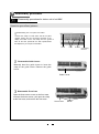
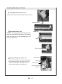
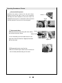
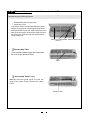
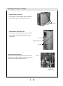
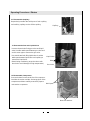
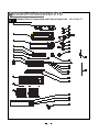
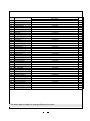
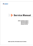
1
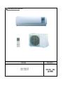
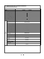
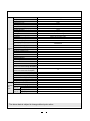
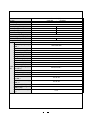
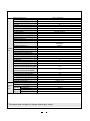
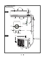
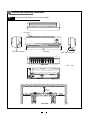
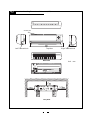
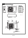
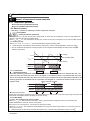
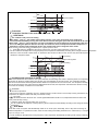
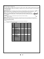
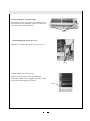
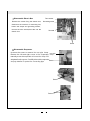
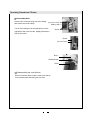
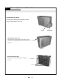
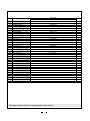
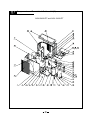
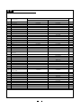
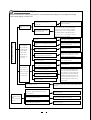
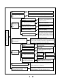
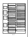
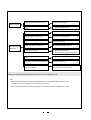
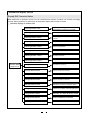
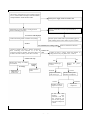
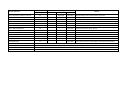
SERVICE MANUAL
NORDIC INVERTER SERIES
ASH-09AIN PT, ASH-12AIN PT
1
Summary and features
Model
ASH-09AIN PT
ASH-12AIN PT
Remark
2. Specifications and Technical Parameters
ASH-09AIN(PT)
Model
Function
Rated Voltage
Rated Frequency
Total Capacity (W/Btu/h)
Power Input (W)
Rated Input (W)
Rated Current (A)
Air Flow Volume (m3/h) (H/M/L)**
Dehumidifying Volume (l/h)
EER / C.O.P (W/W)
Energy Class
Model of Indoor Unit
Fan Motor Speed (r/min)
(H/M/L)
Output of Fan Motor (w)
Input of Heater (w)
Fan Motor Capacitor (uF)
Fan Motor RLA(A)
Fan Type-Piece
Diameter-Length (mm)
Evaporator
Pipe Diameter (mm)
Row-Fin Gap(mm)
Indoor Coil length (l) x height (H) x
unit coil width (L)
Swing Motor Model
Output of Swing Motor (W)
Fuse (A)
Sound Pressure Level dB
(A) (H/M/L)
Sound Power Level dB (A)
(H/M/L)***
Dimension (W/H/D) ( mm)
Dimension of Package
(L/W/H) ( mm)
Net Weight /Gross Weight
(kg)
COOLING
HEATING
1Ph – 220-240V~
50Hz
3000/2500
3200/2750
1350/780
1400/760
1400
1450
6.2
6.3
490
1.2
2.2/3.21
2.3 /3.61
/
ASH-09AIN PT
1160 / 1010 / 890
14
None
1
0.14
Cross flow fan – 1
φ97---583
Aluminum fin-copper tube
7
2-1.4
580X228.6X25.4
MP28VA
2
PCB 3.15A Transformer 0.2A
42 / 39 / 36
49 / 45/ 42
770X190X250
855X272X330
8.5/12.5
Model of Outdoor Unit
Compressor Manufacturer/trademark
Compressor Model
Compressor Type
L.R.A. (A)
Compressor RLA(A)
Compressor Power Input(W)
Overload Protector
Throttling Method
Starting Method
Working Temp Range (℃)
Condenser
Pipe Diameter (mm)
Rows-Fin Gap(mm)
Coil length (l) x height (H) x coil width
(L)
Fan Motor Speed (rpm)
Output of Fan Motor (W)
Outdoor
Fan Motor RLA(A)
unit
Fan Motor Capacitor (uF)
Air Flow Volume of Outdoor Unit
Fan Type-Piece
Fan Diameter (mm)
Defrosting Method
Climate Type
Isolation
Moisture Protection
Permissible Excessive Operating
Pressure for the Discharge Side(MPa)
Permissible Excessive Operating
Pressure for the Suction Side(MPa)
Sound Pressure Level dB (A) (H/M/L)
Sound Power Level dB (A) (H/M/L)
Dimension (W/H/D) ( mm)
Dimension of Package (L/W/H)( mm)
Net Weight /Gross Weight (kg)
Refrigerant Charge (kg)
Length (m)
Gas additional charge(g/m)
Connec
Outer
Liquid Pipe (mm)
tion
Diameter Gas Pipe (mm)
Pipe
Max
Height (m)
Distance Length (m)
ASH - 09AIN (PT)
MITSUBISHI
KNB092FHBMC
rotary
25
3.89
895
None
Capillary throttling
Transducer starting
-10℃≤T≤43℃
Aluminum fin-copper tube
9.52
1-1.6
The above data is subject to change without prior notice.
608X508X22
830±20
30
0.3
2.5
/
Axial fan –1
400
Auto defrost
T1
I
IP24
3.8
1.2
53
63
848X260X540
878X360X590
35/40
R410A / 0.78
4
15
Φ6(1/4”)
Φ9.52(3/8”)
5
10
Model
Function
Rated Voltage
Rated Frequency
Total Capacity (W/Btu/h)
Power Input (W)
Rated Input (W)
Rated Current (A)
Air Flow Volume (m3/h) (H/M/L)**
Dehumidifying Volume (l/h)
EER / C.O.P (W/W)
Energy Class
Model of Indoor Unit
Fan Motor Speed (r/min)
(H/M/L)
Output of Fan Motor (w)
Input of Heater (w)
Fan Motor Capacitor (uF)
Fan Motor RLA(A)
Fan Type-Piece
Diameter-Length (mm)
Evaporator
Pipe Diameter (mm)
Row-Fin Gap(mm)
Indoor Coil length (l) x height (H) x
unit coil width (L)
Swing Motor Model
Output of Swing Motor (W)
Fuse (A)
Sound Pressure Level dB
(A) (H/M/L)
Sound Power Level dB (A)
(H/M/L)***
Dimension (W/H/D) ( mm)
Dimension of Package
(L/W/H) ( mm)
Net Weight /Gross Weight
(kg)
ASH - 12AIN (PT)
COOLING
HEATING
1Ph – 220-240V~
50Hz
4000/3500
4300/4000
1500/1090
1420/1108
1600
1650
7
7.2
550
1.6
2.67/3.21
3.01/3.61
A/A
ASH-12AIN PT
1250/1100/1050
20
None
1
0.152
Cross flow fan
φ92.1—616
Aluminum fin-copper tube
7
2-1.4
681×324.3×38.1
MP28EA
2
Controller3.15 transformer0.2
42 / 39 / 38
52 / 49 / 48
830×285×189
906×385×265
11/14
Model of Outdoor Unit
Compressor Manufacturer/trademark
Compressor Model
Compressor Type
L.R.A. (A)
Compressor RLA(A)
Compressor Power Input(W)
Overload Protector
Throttling Method
Starting Method
Working Temp Range (℃)
Condenser
Pipe Diameter (mm)
Rows-Fin Gap(mm)
Coil length (l) x height (H) x coil width
(L)
Fan Motor Speed (rpm)
Output of Fan Motor (W)
Outdoor
Fan Motor RLA(A)
unit
Fan Motor Capacitor (uF)
Air Flow Volume of Outdoor Unit
Fan Type-Piece
Fan Diameter (mm)
Defrosting Method
Climate Type
Isolation
Moisture Protection
Permissible Excessive Operating
Pressure for the Discharge Side(MPa)
Permissible Excessive Operating
Pressure for the Suction Side(MPa)
Sound Pressure Level dB (A) (H/M/L)
Sound Power Level dB (A) (H/M/L)
Dimension (W/H/D) ( mm)
Dimension of Package (L/W/H)( mm)
Net Weight /Gross Weight (kg)
Refrigerant Charge (kg)
Length (m)
Gas additional charge(g/m)
Connec
Outer
Liquid Pipe (mm)
tion
Diameter Gas Pipe (mm)
Pipe
Max
Height (m)
Distance Length (m)
ASH - 12AIN (PT)
MITSUBISHI
KNB092FHBMC
Double-rotor
33
3.92
960
Int11l-3979
Capillary throttling
Transducer starting
-10℃≤T≤43℃
Aluminum fin-copper tube
7
2-1.4
The above data is subject to change without prior notice.
608/498/22
880±20
30
0.3
2
/
Axial fan-1
400
Auto defrost
T1
I
IP24
3.8
1.2
≤55
≤65
848X260X540
878X360X590
39/43
R410A / 1.17
4
15
Φ6(1/4”)
Φ12(1/2”)
5
10
3
Component Name
Air in
Panel
Display
Indoor unit
Louver
Air out
Zoom in the display
Remote
controller
Heat
Cool
Auto
Power/Run
Fan
Outdoor unit
Power
plug
Drain hose
Dehumidify
Air in
Connection pipe
and connecting wire
Air out
4
Overall and Installing Dimension
Overall and Installing Dimension of Indoor Unit(9K)
Air inlet grill
Left Tube-exit hole
Top View
Rear View
U
U
rear panel
Right Tube-exit hole
Unit:
mm
Overall and Installing Dimension of Indoor Unit(12K)
Air inlet grill
Left Tube-exit hole
Top View
Rear View
U
U
rear panel
Right Tube-exit hole
Unit:
mm
Overall and Installing Dimension of Outdoor Unit
Unit:
Bolt
Nut
Wrench
mm
5. Electrical Diagram
ASH-09AIN PT
ASH-12AIN PT
1
1
,1'22581,7
287'22581,7
6
Manual of functions of remote controller and operation method
Manual of functions of remote controller
6.1.1 Temperature parameter
The room setting temperature(Tpreset)
The room ambient temperature (Tamb)
6.1.2Basic Functions
It will delay 3 minutes for restarting unit after compressor is stoped
.
Cooling Mode
Cooling Conditions and Process
When T amb.≥Tpreset , the unit will run under cooling mode, in which case the compressor \ indoor fan and outdoor fan
will start , the indoor fan will run at setting speed.
When T amb.≤Tpreset -2℃, the compressor will stop, the outdoor fan will atop running after 30 seconds,the indoor fan will
run at setting speed.
When Tpreset -2℃<T amb.< Tpreset +1℃, the unit will maintain its original operating status.
Under this mode, the switchover valve will not be powered on, and the setting temperature range is16 ~30 .
The air conditioner will adjust the running frequency of the compressor automatically according to the change of ambient temperature.
Tpreset
Tamb
Start cooling
Original operating status
Tpreset -2℃
Stop cooling
≥3 min.
Compressor
Outdoor fan
Indoor fan
6.1.2.1.2 Protection
Antifreeze Protection
Preset speed
Stop
Run
When the antifreezing pretection is detected,the compressor will stop,the outdoor fan will stop after 30s , the
indoor fan motor and swing fan motor will run at original run conditions under the cool mode.Indoor fan motor
will run at low speed and indoor fan motor will run at oroginal conditions under the dehumidify mode.When ant
-ifreezing protection is eliminated and the compressor has stopped for 3 minutes,the whole unit will run in the
oroginal mode.
During antifreeze protection
Compressor
3 min.
Outdoor fan
Indoor fan
Stop
Run
Overcurrent protection
If total current is high,the compressor wil run in limited frequency.If total current is over the stop-running current,then the
compressor will stop,the outdoor will delay 30 seconds to stop.
6.1.2.2 DRY Modes
6.1.2.2 .1 The conditions and process of DRY
When T amb. > T preset, the
℃ unit will run under DRY mode, in which case the compressor \indoor fan and outdoor fan
will be started and the indoor fan will run at low speed.
When Tpreset -2<T amb<Tpreset , the unit will run with original setting.
When Tamb.< Tpreset-2℃, the compressor will be stopped, and outdoor fan will be stopped after 30 seconds,the indoor fan
will run at low speed.
Under this mode, the switchover valve will not be powered on, and the setting temperature range is16 ~30 .
The air conditioner will adjust the running frequency of the compressor automatically according to the change of ambient
temperature.
Tamb
Dry
Tpreset
Original condition
Tpreset -2℃
Stop
Compressor
Outdoor fan
Indoor fan
low speed
Protection
Run
Protection function is the same with cool mode
HEAT Mode
Stop
The conditions and process of heating
When Tamb Tset +2 ,the system enters heating running, in this case, the reversal valve, compressor,
out fan enter simultaneously running.The indoor fan will run with setting fan speed and anti-coolwind will be runned.
When Tamb Tset +5 ,the compressor will stop, and outdoor fan will be stopped in 30 seconds,the indoor unit
will run at setting fan speed for 60s then will stop .The switchover valve will be powered off after compressor is
stopped for 2 minutes under heating-off mode or the condition that heat is changed to other modes
When Tset+2 <Tamb<Tset+5 ,unit will keep the original operation status.
Under this mode, the switchover valve will be powered on, and the setting temperature range is16 ~30 .
The air conditioner will adjust the running frequency of the compressor automatically according to the change of ambient temperature.
When the unit is turned off in HEAT mode, or switched to other mode from HEAT mode, the four-way valve will be powered
off after the compressor stops.
Stop running
set
set
Original running state
ambient
a
Start heating
3min
Compressor
Outdoor fan
Indoor fan
2 min
2 min
Reversal vavle
Run
Conditions and processes of defrost
Stop
When frost is detected in the condenser, the system will enter into defrosting state. When defrosting starts, the compressor
and indoor fan will stop, and the outdoor fan and four-way valve will delay 30 seconds to stop. The compressor will start
after 30 seconds and then defrosting will be started. When the compressor has run for 8 minutes , the compressor will stop
After 30 seconds the four-way valve opens and afteranother 60 seconds, the compressor and outdoor fan resume running.
The indoor fan will delay 2 minutes to run at the latest.
Protection
Overcurrent protection
If total current is high,the compressor wil run in limited frequency.If total current is over the stop-running current,then the
compressor will stop,the outdoor will delay 30 seconds to stop.
Fan mode
Under FAN mode,the indoor fan motor can choose high\middle\low\auto mode to run,compressor\outdoor fan motor and
4-way vavle will stop running.
Under this mode, the range of setting tem. is 16-30
The air conditioner will adjust the running frequency of the compressor automatically according to the change of ambient
temperature.
Auto Mode
Under this mode, the system will automatically select its run mode (cool, dehumidify, heat or fan) with the change of
ambient temperature. For protection function, same as under cooling and heating mode.When the ambient temp. is changed,
it prior to change mode.
The air conditioner will adjust the running frequency of the compressor automatically according to the change of ambient
temperature.
Protection function in each mode
Overload protection
When tube temp. is detected high,the compressor runs in limited frequency or slow-frequency.When the temp. is over
standard,then compressor stop running.In auto HEAT or HEAT mode,the indoor fan will blow for 60 seconds and then stop.
In other modes,the indoor fan will run at the setting speed.
Compressor discharge tempreture protection
When the temp. is over the standard,then compressor stop running.When the discharge temp. resume the original conditions
and compressorhas stop running for 3 minutes,the compressor will resume running.
Communication mulfunction
There have communication mulfunction when unit don't receive the correct signal for 3 minutes,the unit will stop running.
Module protection
When module is in protection,the compressor will stop.It will resume running after stopping for 3 minutes.During the period
of module protection,there will display mulfunction in indoor unit,and the total unit will stop running.
Other control
ON/OFF
The switch status is changed one time when pressing the ON/OFF key.
Mode function
Unit will choose and disolay the below mode when pressing mode key:AUTO,COOL DRY,FAN,HEAT,AUTO.
TEMP. setting button
Each time TEMP or TEMP button is pressed, the set temperature will be increased or decreased by 1℃ . Adjusting range
is 16--30℃ . In AUTO mode, this button does not function.
Auto key
If controller is turned on,it will be stoped when pressing this key.If controller is turned off,unit will run with auto
and swing is running when pressing this key.
Timer control
The unit is turned on or off according to the timer set by the remote controller.
Sleep function
When the air conditioner is in COOL or DRY mode, after Sleep mode has been set properly, the preset Tset will be increased
by 1 after the sleep program has run for 1 hour, and Tset will be increased by another 1 after 2 hours. Tset has been
increased by 2 totally in two hours. Then the unit will run at this set temperature and at the set speed.
Tpreset
Setting temp. Tpreset
Tpreset
1hr.
2hrs.
2hrs. above
When the air conditioner is in HEAT mode, after Sleep mode has been set properly, the preset Tset will be decreased by
1 after the sleep program has run for 1 hour, and Tset will be decreased by another 1 after 2 hours. Tset has been
increased by 2 totally in two hours. Then the unit will run at this set temperature and at the set speed.
2hrs.
1hr.
2hrs. above
Tpreset
Tpreset
Tpreset
In FAN and AUTO mode, the set temperature is fixed.
Setting temp. Tpreset
Indoor fan control
Use the remote controller to set the indoor fan running at HIGH, MED or LOW speed.At this time the fan will run
at high, medium or low speed. It can also be set to AUTO.
During switch in each fan speed, there should be 30s at least delay.
(8) Power supply for outdoor unit
The power supply for outdoor unit is turned on in AUTO, COOL, HEAT and DRY mode under turn-on state.
The power supply for outdoor unit will delay 3 minutes to turn off under turn-off state or in the FAN mode
under turn-on state.
Swing control
Use the SWING button of the wireless remote controller to controller SWING On and Off. Swing will only act when indoor
fan is running.After power on, the stepping motor turns back to 0 position and closes the air outlet vent;
after the unit is in cool mode,it will turn back to the max. air outlet D1 position,then swing back to L
position for the next order;When unit is in Heat mode,quide louver stop at D1 position;If the unit is
under swing mode,it will swing betewwn L1 and D1 position.When unit is turned off,it will turn back to
Buzzer
The controller is powered on and detect the signal received, the buzzer will beep.
Memory function
Memory contents of power off: Mode, Swing, Set temp., Set fan speed, Timer ect; when unit is turned On, when repowered on,
there should be 3 minutes above then can supply power to outdoor unit; when unit is off, when repowered on, the indoor unit can
supply power to outdoor unit at once.
Compressor delay protection
In Cool, Dry, Heat modes, every start of compressor there should be 3 minutes delay.
Outdoor unit malfunction display
Malfunction
Compressor opened
5
6
7
8
9
10
11
12
13
14
15
16
17
Red
Yellow
Green
Blink once
Defrosting
Blink twice
Anti-freezing protection
Blink three times
IPM protection
Over current
protection
Overload unit stop
protection
Air exhaust unit stop
protection
Blink 4 times
Blink 5 times
Blink 6 times
Blink 7 times
Compressor overload
Blink 8 times
protection
Limit requency (currency) Blink once
Frequency declined
Blink twice
(Air exhasut)
Frequency limit
Blink 3 times
(Overload)
Frequency declined
Blink 4 times
(anti-freezing)
Outdoor tube temp
Blink 5 times
sensor malfunction
Outdoor ambient temp Blink 6 times
sensor malfunction
Blink 7 times
Outdoor air exhaust
temp sensor malfunction
Arrive at temp. of
Blink 8 times
unit on
Communication is normal
Normal
7 Disassembly procedures
Disassembly procedures for indoor unit of unit 9KK
Operation procedures/pictures
Disassembling the front panel and filters
Unloose the clasps on both sides and lift the panel
upward. Unplug the two connecting terminals of the
display and slide out the rear clasp from the groove to
take off the front panel.Push the filter upward,loosen
the clasps,then you can pull out the filters
Panel
Filter
Disassemble Guide Louver
Manually bend the guide louver to loose the
clasp at the guide louver. Remove the guide
louver.
Guide Louver
Disassemble Front Case
Open the three screw covers at the front case,
unscrew the three screws, pull open the clasp
at the front case, and remove the front case.
Screw cover
Screw
Screws Connecting
terminal
Operating Procedures / Photos
Disassemble Electric Box Cover
Lossen three clasos, then remove the electric box cover
Electric Box Cover
Disassemble Water Tray
Pull open the holding clasp on the left side of the
water tray, disconnect the terminal of the stepping
motor, lift and pull out the drainage pipe, and
remove the water tray.
Water Tray
Clasp
Terminal
Disassembling the electric box
Screw off the two pieces of screws that fix the electric
box and unloose the clasp. Pull out the tube sensor,
unloose the grounding nut and unplug the motor
connecting terminal take out the electric box.
Tube sensor
Screw
Grounding nut
Motor connecting
terminal
Clasp
Operating Procedures / Photos
Disassemble Evaporator
Unscrew the screw to remove the rear pipe clamp.
Remove the left and right screws at the evaporator,
manually move the evaporator to loosen the clasp of its
side plate from the groove. Carefully take out the evaporator
and pay attention to protect the connecting pipe.
Screw
Screw
Disassemble Motor
Unscrew the three screws fixing the motor clamp, Screw
and remove the motor clamp.
Motor Clamp
Loosen the holding nut at the shaft sleeve on the
right side of the cross flow fan. Slightly lift and then
pull out the motor.
Tighten nut
Disassembling the cross flow fan
Refer to the above steps to take out the cross flow fan
from the base plate after taking out the motor.
Fixing nut
Disassembly procedures for indoor unit of unit 12k
Operation procedures/pictures
Disassembling the front panel and
electric box cover
Unloose the clasps on both sides and lift the panel
upward. Unplug the two connecting terminals of the
display and slide out the rear clasp from the groove to
take off the front panel. Screw off the fixing screws of
the electric box cover and open the electric box top
cover to take it off.
Panel Connecting Screws Cover of electric box
terminal
Disassemble Filter
Push the filter upward,loosen the clasps,then
can remove two pieces of filters
Filter
Disassemble Guide Louver
Manually bend the guide louver to loose the
clasp at the guide louver. Remove the guide
louver.
Guide Louver
8.1.4
4.Disassembling the front panel body
Unclench the 3 screw covers and screw off the 4 pieces
of screws that fix the panel body. Unloose the front and
rear clasp to take off the panel body.
Screw
8.1.5
5.Disassembling the electric box cover
Unloose the 3 clasps to take off the electric box cover.
8.1.6
Clasp
6.Disassembling the water-tray assy
Unloose the clasp on the left side and unplug the
connecting terminal of the stepping motor. Be careful
because the drainage pipe is placed here.
Screw
Disassemble Electric Box
Remove the screw fixing the electric box,
Tube sensor
Grounding screw
disconnect the terminal of connecting line,
loosen the clasps and grounding screws,
remove the tube sensor,then take out the
electric box.
Terminal
Screw
Disassemble Evaporator
Unscrew the screw to remove the rear pipe clamp.
Rear pipe
Remove the left and right screws at the evaporator, clamp
manually move the evaporator to loosen the clasp of its
side plate from the groove. Carefully take out the evaporator
Screw
and pay attention to protect the connecting pipe.
Screw
Screw
Operating Procedures / Photos
Disassemble Motor
Unscrew the 4 screws fixing the motor clamp,
and remove the motor clamp.
Right motor Clamp
Bearing seat
Loosen the holding nut at the shaft sleeve on the
right side of the cross flow fan. Slightly lift and then
pull out the motor.
Screw
Screw
Left motor Clamp
Motor
Holding Screw
Screw
Disassembling the cross flow fan
Refer to the above steps to take out the cross flow fan
from the base plate after taking out the motor.
Disassembly Procedure of Outdoor Unit
1.Disassemble Big Handle
Unscrew the screw fixing the big handle,and then
remove it downwards to take it out.
Screw
2.Disassemble Top Cover
Unscrew the 2 screws fixing left side of top cover
and the 1 screw fixing the right side to remove the
Screw
top cover.
3.Disassemble Rear Grill
Unscrew the 4 screws fixing the rear grill to
Rear Grill
remove it.
Screw
Big Handle
Operating Procedures / Photos
4.Disassemble Front Panel
Unscrew the 5 screws fixing the panel and dextrorotate the front panel to pull it out from groove.
Screws
5.Disassemble Right Side Plate
Unscrew the 2 screws fixing electric box ,and then
unscrew the 5 screws fixing the right side plate
to remove it.
Screws
Right Side Plate
Screws
6.Disassemble Electric Box
Unscrew the screws fixing the electric box, and then
Screw
pull out the inset block of lead-out wire of compressor
and fan motor to take out the electric box.
Electric Box
24
Operating Procedures / Photos
7.Disassemble Axial Flow Fan
Loosen the fastening nut fixing the axial flow fan with
Axial Flow Fan
a spanner ,and then take out the nut,spring gasket
and flap gasket in turn.
Nut
8.Disassemble Motor and Motor Support
Unscrew the 4 screws fixing the motor to take out
the motor,and then unscrew the 2 screws fixing the
motor support to take it out.
Screws
Motor
Screw
9.Disassemble Four-way Valve
Unscrew the fastening nut of the four-way valve coil
and remove the coil. Wrap the four-way valve with
wet cotton and unsolder the 4 weld spots connecting
the four-way valve to take it out. (Note:Refrigerant
should be discharged firstly.)
Welding process should be as quick as possible and
Four-way valve
Four-way
valve coil
keep wrapping cotton wet all the time. Be sure not to
burn out the lead-out wire of compressor.
Weld spots
25
Operating Procedures / Photos
10. Disassemble Capillary
Respectively unsolder the weld spots of main capillary
and auxiliary capillary to take off the capillary.
Capillary
11.Disassemble Gas and Liquid Valves
Unscrew the two bolts fixing gas valve and liquid
valve.Unsolder weld spots between gas valve and
and air-return pipe to remove the gas valve.
Unscrew the two bolts fixing liquid valve. Unsolder
weld spots between liquid valve and capillary to
Liquid Valve
remove the liquid valve.
(Note:During unsoldering ,wrap the valves with
wet cloth to avoid damage for high temperature.)
Bolts
Gas Valve
12.Disassemble Compressor
Unscrew the three foot-nuts at the foot of the compressor.
Unsolder the suction and the discharge pipes of the
compressor,and then carefully remove the pipes to
take out the compressor.
Weld spots
Nuts with washers
26
8
Exploded View of Components and Parts of Indoor Unit
ASH-09AIN PT
No
Description
1
2
3
4
5
6
7
8
9
10
11
12
13
14
15
16
17
18
19
20
21
22
23
24
25
26
27
28
29
30
31
32
33
34
35
36
37
38
39
Wall-Mounting Frame
Rear Case
Evaporator Assy
Cross Flow Fan
Ring of Bearing
Fan Bearing
Drainage Pipe
Water Tray
Swing Louver
Swing Linkage 1
Swing Linkage 2
Front Case
Screw Cover
Filter
Remote Control Y612C-B
Decorate Piece
Receiver Board
Front Panel
Guide Louver 2
Guide Louver 1
Motor MP28VA
Motor Clamp A
Motor FN14A
Electric Box Cover
Terminal Board T4B3A
Covering Plate
Electric Box
Main PCB 9M82
Transformer 48X26G
Wire Clamp
Rear Clamp
Connecting Cable
Power Cord
Room Sensor 15K
Tube Sensor 20K
swing louver clamp
swing louver
swing louver(up)
swing louver(down)
Part Code
ASH-09AIN
01252220
222020016
0100209319
10352001
76512203
/
0523001401
201820272
10512080
10582002
10582003
200022105
242520062
11122002
30511005
68012019
30545702
200022092
105120342
105120332
15212110
26112014
150121081
22242030
42011233
201220061
20102178
30039046
43110233
71010103
24242001
400205235
400204643
390000451
390000591
10582409
10582408
10542004
10542005
The above data is subject to change without prior notice.
Qty
1
1
1
1
1
1
1
1
1
1
1
1
3
2
1
1
1
1
1
1
1
1
1
1
1
1
1
1
1
1
1
1
1
1
1
1
1
1
1
Exploded View of Components and Parts of Indoor Unit
ASH-12AIN PT
No
Description
1
2
3
4
5
6
7
8
9
10
11
12
13
14
15
16
17
18
19
20
21
22
23
24
25
26
27
28
29
30
31
32
33
34
35
Wall-Mounting Frame
Rear Case
Evaporator Assy
Cross Flow Fan
Ring of Bearing
Fan Bearing
Drainage Pipe
Water Tray
Swing Louver
Swing Linkage
Front Case
Screw Cover
Filter
Remote Control YB1B4
Front Panel
Decorate Piece
Receiver Board
Guide Louver
Guide Louver
Motor MP28VA
Motor Left Clamp
Motor Right Clamp
Motor FN20G
Electric Box Cover
Terminal Board T4B3A
Covering Plate
Electric Box
Main PCB 9H82
Transformer 57X25C
Wire Clamp
Rear Clamp
Connecting Cable
Power Cord
Room Sensor 15K
Tube Sensor 20K
Part Code
ASH-12AIN PT
01252384
22202050
010020212
10352005
76712015
76512210
0523001401
201820394
105120413
10582439
200022956
24252007
11122440
30511005
200022921
68012019
30545558
261120432
261120422
15212105
261124281
26112429
15012058
22242017
42011233
20102123
20102108
30039085
43110237
71010003
26112425
40020538
400204643
390000451
390000591
The above data is subject to change without prior notice.
Qty
1
1
1
1
1
1
1
1
1
1
1
3
2
1
1
1
1
1
1
1
1
1
1
1
1
1
1
1
1
1
1
1
1
1
1
Components and Parts List of Outdoor Unit(2)
ASH-09AIN PT and ASH-12AIN PT
No
Description
1
2
3
4
5
6
7
8
9
10
11
12
13
14
15
16
17
18
19
20
Front Panel
Clap Board
Heating cable (chassis)
Reactor
Box
PFC Inductance 0.8mH/20A
Drainage Connecter
Reactor Support
Overload Protector
Compressor
Heating cable
Compressor Gasket
Bolt
Nut
Valve Support
Right Side Plate
Valve
Valve
Capillary Assy
One Way Valve
4-Way Valve
4-way Rever-sing Valve
Component
Big Handle
4-way Valve Coil
Wire Clap
Insulation Piece D
Terminal Board A
Electric Box 2
Electric Box
PCB
Temperature Sensor
Sensor 20K
Exhaust Gas Temperature
Sensor 50K
Electric Box Cover
Rectifier S25VB60
Sensor Insert
Radiator
Rear Grill
Condenser Assy
Top Cover Assy
Motor Support
Motor
Axial Flow Fan
Nut
Front Grill
21
22
23
24
25
26
27
28
29
30
31
32
33
34
35
36
37
38
39
40
41
42
43
44
Part Code
ASH-09AION PT
ASH-12AIN PT
Qty
01533005
01233012
/
01403617
/
06123401
01203682P
/
00120228
76513004
/
70210108
70310011
01713041
0130200401
07100003
07100005
0310333305
/
430004022
01533005
01233012
76510004
01413504
99070120
06123401
0120352402
00183003
00120228
76513004
76710236
70210108
70310013
01713041
01303048
07100006
07100003
031030716
071301025
430004032
1
1
1
1
1
1
1
1
1
1
3
3
3
1
1
1
1
1
1
1
03123042
03123013
1
26233433
430004002
71010003
70410525
42011113
01403998
20113005
301380021
39000208
390001921
26233433
430004002
71010003
70410525
42011113
01413116
20113005
30039155
39000208
39000071
1
1
1
1
1
1
1
1
1
1
39000016
39000016
1
01413048
/
42020063
49010065
01473023
0110359012
01253261
01705002
150130671
10333414
70310131
22413431
01413048
46010602
42020063
49010213
01473030
0111308202
01253261
017030531
15013067
10333004
70310131
22413431
1
1
1
1
1
1
1
1
1
1
1
1
9 Failure and analysis
Analysis in this section is used for Linge Wind D.C. Inverter Series. Before analysis, you can diagnose according
to the indicator display on outdoor unit.
The breaker trips at once when it
Measure insulation resistance to ground to see
if there is any leakage.
is set to "ON".
Trip of breaker or blow
of fuse
The circuit or the part of the air conditioner has
malfunction. They heat and break the insulation
The breaker trips in few minutes
when it is set to "ON"
and lead to short circuit or creepage. Measure
the insulation resistance or eliminate the malfunction one by one. If the breaker itself has
Air conditioner can not start up
malfunction, then replace the breaker.
No power
Check power supply circuit.
Power plug is not well plugged in and poor connection
Check if the plug is properly plugged in and
make the loose contact firm.
The air conditioner
does not react after
it is powered ( after
Fuse of controller burnt out
Change controller fuse
the plug is inserted,
the buzzer does
The transformer connection is loose or has bad
not sound and the
contact or the transformer has malfunction
Fasten the wiring; measure the output
voltage of the transformer, if it is
incorrect, change the transformer
remote startup has
no response)
The remote controller
Controller is broken
Check remote controller
Remote controller is short of power
Change batteries
Remote controller malfunction
First, press the manual switch button AUTO,
does not receive
signals (after it is
if there is no response,check based on the
powered, the buzzer
above methods. If it runs normally after
will sound, unless it
has
Receiver loose or poor connection
pressing the button,check again whether the
installation position and the connection wire
malfunction)
of the reception head is correct. If it is
correct,then replace the receiver or the re-
Receiver is broken
mote controller.
heck the voltage. If it is lower than 10£¥ of the rated voltage, check the
Power voltage is too low
cause, improve the power supply condition and add the stabilized voltage
power supply.
Controller malfunction (IC2003 broken,
creepage of
parallel capacitor of relay loop,
relay is broken etc.)
In cool, heat mode,the
outdoor
unit and compressor
will not run.
Change controller
Wire loose or wrong connection
Correctly wire according to the drawing
Improper setting of temperature
Adjust setting temp.
Improper set of temperature
Adjust set temperature
If cooling (heating) load is
proper
Check the forecasted load of cooling (heating)
The refrigerant has leakage or is
insufficient
Malfunction of
refrigerant
flow
Leakage between the high pressure and the low pressure inside the compressor
Malfunction of four-way valve
Poor COOL(HEAT) operation
Local block of capillary
Blockage of cooling system
Heat insulation for the connection
pipes of the indoor unit and the outdoor unit is bad.
heck and fill the leakage, then
vacuumize it and supplement the refrigerant as required
Replace the compressor
Replace the four-way valve
Replace the capillary
Judge whether the system is blocked by
observing the condensation of evaporator and the pressure value of the high
pressure manometer and take measures
to deal with the system.
Make sure that heat insulation for the thick and thin pipes
is good. Heat insulation must also be provided for the
joint andthe exposed part of the copper pipe .
Block of outdoor heat exchanger
Clean the dust accumulated on the surface of
the heat exchanger.
Air filter were blocked
Clean the filter
Fan speed was set too slow
Air circulation
is insufficient
Fan rotation speed becomes
low
The installation position of the
outdoor unit is not appropriate.
The outdoor temperature is too high.
The air tightness is not enough. People
come in and out too frequently. There
are heating devices indoors.
To set the fan speed to high or
middle speed
Capacitor
damage
Replace the capacitor
Motor damage
Replace the motor
Good ventilation must be provided for the
installation position of the outdoor unit.
Properly install the rainproof plate or the sunproof plate. If the
maximum cool air still can not meet the requirement, it is suggested to replace the air conditioner.
Keep certain air tightness indoors, try not to use
electricalappliance with large quantity of heat
The indoor fan motor is burned or breaks
or has the heat protector malfunction.
The fan does not
run when it is set
to supply air.
In the cooling and
heating mode, the
compressor runs,
but the outdoor fan
does not run.
The compressor is too hot
and leads to
the action of the
protector.
The built-in heat protector of the motor
breaks frequently because the motor
is abnormal.
Replace the fan motor
Wrong connection
Make the correction connection based on the
circuit drawing.
The fan capacitor has open circuit or is
damaged.
Replace the fan capacitor of the same type
and same specification.
The outdoor fan motor is damaged.
Replace the fan motor
Wrong connection
Make the correct connection based on the
circuit drawing
The outdoor fan capacitor is damaged.
Replace the fan capacitor
Malfunction of compressor
Replace the compressor
Breakage of running capacitor of
compressor
Replace the capacitor
The voltage is too low or too high.
Manostat is recommended.
Wrong wire connection
Connect the circuit diagram correctly
The protector itself has malfunction.
The refrigerant is not enough or is too
much.
The compressor is too hot
and leads to the
action of the
protector.
Replace the fan motor or the defective part.
The capillary is blocked and the temperature rises.
The compressor does not run
smoothly or is stuck. The air discharge valve is damaged
The protector itself has malfunction.
Use the multimeter to check whether the contact of the compressor is on when it is not
overheated. If it is not on, then replace the protector
Adjust the volume of the refrigerant
Replace the capillary
Replace the compressor
Replace the protector
The torque of the swing motor is not
enough
The swing fan
does not run.
Wrong connection
The controller is damaged(IC2003 is
damaged, the swing relay can not
close, etc)
First, check whether the connection is
wrong. If no, replace the parts
Drainage pipe blocked or broken
Change drainage pipe
Water leakage
Wrap of refrigerant pipe joint is not close
enough.
Re-wrap and make it tight.
Fan of indoor unit contacts other parts.
Adjust fan location.
Foreign object in indoor unit
Take out the foreign object.
Compressor shakes too much.
Adjust support washer of compressor, and
tighten loosen screws.
Touch of pipeline of outdoor unit
Separate the touching pipeline.
Touch of inner plates
1. Tighten connect screw.
Abnormal sound
and shake
2. Stick absorbing clay between plates.
Louver of outdoor unit touched outer
case.
Adjust location of louver.
Abnormal sound inside compressor
Change compressor
Abnormal solenoid sound from 4-way
valve when heating
Circuit-short inside solenoid of the valve
and change the solenoid valve.
There are no heating malfunctions in the above for the cooling only unit.
Note:
1. When maintaining, before detecting the voltage between the modular PN is less than 50V, please
never touch any of the terminals, in order to avoid electric shock.
2. When replacing the batteries, commutating bridge, both of them should be coated with the coolant.
Malfunction display section
Trendy D.C. Inverter Series
When malfunction or protection occurs in the air conditioner,the indicator of outdoor unit will blink accordingly
as well. When protection or malfunction is eliminated, display will be back to normal
Indicator display of outdoor unit
Yellow light blinks 1 time
Yellow light blinks 2 times
Yellow light blinks 3 times
Indicator display
of outdoor unit
Compressor is running (this is normal condition
and the display of indoor unit is normal)
Defrosting (Normal display)
Antifreezing protection (display of indoor unit
is normal
Yellow light blinks 4 times
IPM module protection
Yellow light blinks 5 times
Overcurrent protection
Yellow light blinks 6 times
Overload protection
Yellow light blinks 7 times
Discharge protection
Yellow light blinks 8 times
Compressor overload protection
Red light blinks 1 time
Limit frequency (currency)
Red light blinks 2 times
Frequency declined (air exhaust)
Red light blinks 3 times
Limit frequency (overload)
Red light blinks 4 times
Frequency declined (air exhaust)
Red light blinks 5 times
Malfunction of outdoor condenser sensor
Red light blinks 6 times
Malfunction of outdoor environmental sensor
Red light blinks 7 times
Malfunction of outdoor discharge sensor
Red light blinks 8 times
Starting temperature is reached
Green light does not blink
Communication malfunction
Analysis or handling of some of the malfunction display:
Compressor discharge protection
Possible reasons: shortage of refrigerant; blockage of air filter; poor ventilation or air flow short pass
for condenser; the system has noncondensing gas (such as air, water etc.); blockage of capillary assy
(including filter); leakage inside four-way valve causes incorrect operation; malfunction of compressor;
malfunction of protection relay; malfunction of discharge sensor; outdoor temperature too high.
Handling method: refer to the malfunction analysis in the above section.
Low voltage overcurrent protection
Possible reason: Sudden drop of supply voltage.
Communication malfunction
Handling method: Check if communication signal cable is connected reliably
Sensor open or short circuit
Handling method: Check whether sensor is normal, connected with the corresponding position on the
controller and if damage of lead wire is found
Compressor overload protectio
Possible reasons: shortage of refrigerant; blockage of capillary and increase of suction temperature;
improper running of compressor, burning in or stuck of bearing, damage of discharge valve;
malfunction of protector.
Handling method: adjust refrigerant amount; replace the capillary; replace the compressor; use universal meter
to check if the contactor of compressor is fine when it is not overheated, if not replace the protector.
System malfunction
i.e. overload protection. When tube temperature (Check the temperature of outdoor heat exchanger when
cooling and check the temperature of indoor heat exchanger when heating) is too high,protection will be activated.
Possible reasons: Outdoor temperature is too high when cooling; insufficient outdoor air circulation;
please refer to the malfunction analysis in the previous section for handling method for refrigerant flow.
IPM module protection
Processing method:Once the module malfunction happens,if it persists for a long time and can not be self- canceled,
cut off the power and turn off the unit,and then re-energize the unit again after about 10 min.After repeating the
procedure for sever times, if the malfunction still exists,replace the module.(refer to the next page)
Check if the voltage between power module P and N is
too low, if the current is too high.In normal condition,
voltage between P and N should be 310V.
Check power supply circuit of outdoor unit
Check if radiating paste is spread evenly or radiating
sticker is stuck well; if screws of power module is
tightened
Temperature of power module is too high, which
causes overheating protection
Protection is still displayed
Reinstall power module and re-spread radiating paste or
stick radiating sticker on the radiator of power module.
Confirm the setting status of outdoor unit (cooling)
Normal
Poor radiation, heat exchanger is dirty
Remove obstructions and clean
Confirm if outdoor fan motor is running; unplug the
three connecting wires between U, V, W of Outdoor fan
Confirm if there is voltage output and balance of
compressor and power module. Turn on the unit to see runs
voltage between any two phases of U, V and W.
if outdoor fan runs normally (more than 3 minutes)
Outdoor fan stops
No
Yes
Measure the voltage of outdoor
fan connector
No voltage
Replace the
mainboard of
outdoor unit
Whether module type
is correct
Normal
voltage
Replace the fan
motor
Replace
module
Measure the three-phase
resistance of compressor
Normal
Whether cylinder of
compressor is stuck
If the unit runs
normally
after
connected with the
new compressor for
trial run, the cylinder
of original compressor
is stuck
—
—
power
Normal
Abnormal
Replace the module
with correct type
the
Abnormal
Replace the
compressor
Name of malfunction
Display of indoor unit
ERROR CODE
State of the lamps on the outdoor unit PCB
GREEN-LED2
RED-LED3
YELLOW-LED4
blink 4 times
Reasons
Stop for anti-freezing protection of indoor unit
E2
blink 3 times
refrigerant leakage, indoor unit airflow blocked up, filter duty
Stop for exhaust protection
E4
blink 7 times
less refrigerant, capillary blocked up, ambient temperature is unsuitable
Stop for low voltage protection
E5
blink 5 times
low voltage, ambient temperature is unsuitable
Stop for communication malfunction
E6
Stop for compressor overload protection
H3
blink 8 times
compressor shell oer heat, less refrigerant, capillary blocked up
Overload protection
H4
blink 6 times
ambient temperature is unsuitable, heat exhanger blocked up
Stop for IPM module protection
H5
blink 4 times
IPM modul over heat, low voltage, silica gel
Indoor ambient temperature sensor malfunction
F1
terminal connect not reliable, temperature sensor malfunction
Indoor tube temperature sensor malfunction
F2
terminal connect not reliable, temperature sensor malfunction
Outdoor ambient temperature sensor malfunction
F3
blink 6 times
terminal connect not reliable, temperature sensor malfunction
Outdoor tube temperature sensor malfunction
F4
blink 5 times
terminal connect not reliable, temperature sensor malfunction
Outdoor exhaust temperature sensor malfunction
F5
blink 7 times
Automatic defrosting
H1
REMARK:
don´t blink
communication line failure, main PCB failure, interfere source, connect line wrong
terminal connect not reliable, temperature sensor malfunction
blink 2 times
H1 isn´t an error code, it´s a normal operation. Just heat pump has this function.
1. Error codes can only be seen in the type which has the temperature display PCB. If some type hasn´t this function, the lamps on the outdoor PCB are available then.
2. Normally, the communication between indoor unit and outdoor unit is successful, the green lamp (Led2) of outdoor PCB blinks 1sec. on, 1sec. off.
3. The red and yellow lamp blinks 0.5 sec. on, 0.5 sec. off, between two error display cycle, it will be 2 sec. off.
4. Led1 (red) is power lamp. Led3 (red) blinks 8 times which means temperature be up to machine run. When compressor starts, Led4 (yellow) blinks 1 times.