1
Model 729A
Liquid Nitrogen Level Monitor
Operating and Service Manual
Printed in U.S.A.
ORTEC® Part No. 733770
Manual Revision D
1202
Advanced Measurement Technology, Inc.
a/k/a/ ORTEC®, a subsidiary of AMETEK®, Inc.
WARRANTY
ORTEC* warrants that the items will be delivered free from defects in material or workmanship. ORTEC makes
no other warranties, express or implied, and specifically NO WARRANTY OF MERCHANTABILITY OR
FITNESS FOR A PARTICULAR PURPOSE.
ORTEC’s exclusive liability is limited to repairing or replacing at ORTEC’s option, items found by ORTEC to
be defective in workmanship or materials within one year from the date of delivery. ORTEC’s liability on any
claim of any kind, including negligence, loss, or damages arising out of, connected with, or from the performance
or breach thereof, or from the manufacture, sale, delivery, resale, repair, or use of any item or services covered
by this agreement or purchase order, shall in no case exceed the price allocable to the item or service furnished
or any part thereof that gives rise to the claim. In the event ORTEC fails to manufacture or deliver items called
for in this agreement or purchase order, ORTEC’s exclusive liability and buyer’s exclusive remedy shall be release
of the buyer from the obligation to pay the purchase price. In no event shall ORTEC be liable for special or
consequential damages.
Quality Control
Before being approved for shipment, each ORTEC instrument must pass a stringent set of quality control tests
designed to expose any flaws in materials or workmanship. Permanent records of these tests are maintained for
use in warranty repair and as a source of statistical information for design improvements.
Repair Service
If it becomes necessary to return this instrument for repair, it is essential that Customer Services be contacted in
advance of its return so that a Return Authorization Number can be assigned to the unit. Also, ORTEC must be
informed, either in writing, by telephone [(865) 482-4411] or by facsimile transmission [(865) 483-2133], of the
nature of the fault of the instrument being returned and of the model, serial, and revision ("Rev" on rear panel)
numbers. Failure to do so may cause unnecessary delays in getting the unit repaired. The ORTEC standard
procedure requires that instruments returned for repair pass the same quality control tests that are used for
new-production instruments. Instruments that are returned should be packed so that they will withstand normal
transit handling and must be shipped PREPAID via Air Parcel Post or United Parcel Service to the designated
ORTEC repair center. The address label and the package should include the Return Authorization Number
assigned. Instruments being returned that are damaged in transit due to inadequate packing will be repaired at the
sender's expense, and it will be the sender's responsibility to make claim with the shipper. Instruments not in
warranty should follow the same procedure and ORTEC will provide a quotation.
Damage in Transit
Shipments should be examined immediately upon receipt for evidence of external or concealed damage. The carrier
making delivery should be notified immediately of any such damage, since the carrier is normally liable for damage
in shipment. Packing materials, waybills, and other such documentation should be preserved in order to establish
claims. After such notification to the carrier, please notify ORTEC of the circumstances so that assistance can be
provided in making damage claims and in providing replacement equipment, if necessary.
Copyright © 2002, Advanced Measurement Technology, Inc. All rights reserved.
*ORTEC® is a registered trademark of Advanced Measurement Technology, Inc. All other trademarks used
herein are the property of their respective owners.
iii
CONTENTS
WARRANTY . . . . . . . . . . . . . . . . . . . . . . . . . . . . . . . . . . . . . . . . . . . . . . . . . . . . . . . . . . . . . . . . . . . . . . . ii
SAFETY INSTRUCTIONS AND SYMBOLS . . . . . . . . . . . . . . . . . . . . . . . . . . . . . . . . . . . . . . . . . . . . . . . iv
SAFETY WARNINGS AND CLEANING INSTRUCTIONS . . . . . . . . . . . . . . . . . . . . . . . . . . . . . . . . . . . . . v
1. DESCRIPTION . . . . . . . . . . . . . . . . . . . . . . . . . . . . . . . . . . . . . . . . . . . . . . . . . . . . . . . . . . . . . . . . . . . 1
2. SPECIFICATIONS . . . . . . . . . . . . . . . . . . . . . . . . . . . . . . . . . . . . . . . . . . . . . . . . . . . . . . . . . . . . . . . .
2.1. INPUT . . . . . . . . . . . . . . . . . . . . . . . . . . . . . . . . . . . . . . . . . . . . . . . . . . . . . . . . . . . . . . . . . . .
2.2. OUTPUTS . . . . . . . . . . . . . . . . . . . . . . . . . . . . . . . . . . . . . . . . . . . . . . . . . . . . . . . . . . . . . . . .
2.3. CONTROLS . . . . . . . . . . . . . . . . . . . . . . . . . . . . . . . . . . . . . . . . . . . . . . . . . . . . . . . . . . . . . . .
2.4. ELECTRICAL AND MECHANICAL . . . . . . . . . . . . . . . . . . . . . . . . . . . . . . . . . . . . . . . . . . . . . .
2.5. ACCESSORY . . . . . . . . . . . . . . . . . . . . . . . . . . . . . . . . . . . . . . . . . . . . . . . . . . . . . . . . . . . . . .
2
2
2
2
2
2
3. INSTALLATION . . . . . . . . . . . . . . . . . . . . . . . . . . . . . . . . . . . . . . . . . . . . . . . . . . . . . . . . . . . . . . . . . .
3.1. POWER CONNECTION . . . . . . . . . . . . . . . . . . . . . . . . . . . . . . . . . . . . . . . . . . . . . . . . . . . . . .
3.2. SIGNAL CONNECTION . . . . . . . . . . . . . . . . . . . . . . . . . . . . . . . . . . . . . . . . . . . . . . . . . . . . . .
3.3. DETECTOR BIAS SUPPLY CONNECTION . . . . . . . . . . . . . . . . . . . . . . . . . . . . . . . . . . . . . . .
3.4. INITIAL CONTROL SETTING . . . . . . . . . . . . . . . . . . . . . . . . . . . . . . . . . . . . . . . . . . . . . . . . . .
3
3
3
3
3
4. OPERATING INSTRUCTIONS . . . . . . . . . . . . . . . . . . . . . . . . . . . . . . . . . . . . . . . . . . . . . . . . . . . . . . .
4.1. INITIAL SETUP . . . . . . . . . . . . . . . . . . . . . . . . . . . . . . . . . . . . . . . . . . . . . . . . . . . . . . . . . . . .
4.2. REFILLING DEWAR . . . . . . . . . . . . . . . . . . . . . . . . . . . . . . . . . . . . . . . . . . . . . . . . . . . . . . . . .
4.3. NORMAL OPERATION . . . . . . . . . . . . . . . . . . . . . . . . . . . . . . . . . . . . . . . . . . . . . . . . . . . . . .
4
4
4
4
5. MAINTENANCE . . . . . . . . . . . . . . . . . . . . . . . . . . . . . . . . . . . . . . . . . . . . . . . . . . . . . . . . . . . . . . . . . . 4
iv
SAFETY INSTRUCTIONS AND SYMBOLS
This manual contains up to three levels of safety instructions that must be observed in order to avoid
personal injury and/or damage to equipment or other property. These are:
DANGER
Indicates a hazard that could result in death or serious bodily harm if the safety instruction
is not observed.
WARNING
Indicates a hazard that could result in bodily harm if the safety instruction is not observed.
CAUTION
Indicates a hazard that could result in property damage if the safety instruction is not
observed.
Please read all safety instructions carefully and make sure you understand them fully before attempting to
use this product.
In addition, the following symbol may appear on the product:
ATTENTION–Refer to Manual
DANGER–High Voltage
Please read all safety instructions carefully and make sure you understand them fully before attempting to
use this product.
v
SAFETY WARNINGS AND CLEANING INSTRUCTIONS
DANGER
Opening the cover of this instrument is likely to expose dangerous voltages. Disconnect the
instrument from all voltage sources while it is being opened.
WARNING Using this instrument in a manner not specified by the manufacturer may impair the
protection provided by the instrument.
Cleaning Instructions
To clean the instrument exterior:
! Unplug the instrument from the ac power supply.
! Remove loose dust on the outside of the instrument with a lint-free cloth.
! Remove remaining dirt with a lint-free cloth dampened in a general-purpose detergent and water
solution. Do not use abrasive cleaners.
CAUTION To prevent moisture inside of the instrument during external cleaning, use only enough liquid
to dampen the cloth or applicator.
!
Allow the instrument to dry completely before reconnecting it to the power source.
vi
1
ORTEC MODEL 729A
LIQUID NITROGEN LEVEL MONITOR
1. DESCRIPTION
The ORTEC 729A Liquid Nitrogen Level Monitor is
a NIM-standard single-width module used to sense
whether or not the supply of liquid nitrogen in a
dewar is adequate to maintain the temperature of a
cryogenic detector. Some detectors will be
damaged if allowed to warm up while others can be
warmed up but must not have bias applied unless
they are cold. For either class of cryogenic detector,
the 729A provides protection to the detector if the
supply of liquid nitrogen in the dewar is permitted to
become depleted.
When the liquid nitrogen level drops too far in the
dewar, the 729A provides an alarm and disables the
detector bias supply so that no bias voltage can be
applied to the detector while there is any danger of
having it warm up. The 729A module requires an
accessory sensing element, which is a highsensitivity thermistor mounted in a stainless steel
tube that extends down into the dewar from its filler
cap to a point about 25% from the bottom of the
dewar. The sensor is connected to the module by a
coaxial cable. The tube must be custom-built for
each application.
A bridge-type circuit in the module is used to sense
changes of resistance of the thermistor when its
temperature changes. When the supply of liquid
nitrogen in the dewar is deep enough to immerse
the end of the probe, the thermistor is cold and the
bridge is balanced. If the liquid nitrogen level
becomes depleted enough that the probe is no
longer immersed, the thermistor warms and
unbalances the bridge. Then a front panel red light
flashes, a buzzer sounds, and the detector bias
supply is disabled. The module goes into the alarm
condition when the sensor temperature rises
approximately 10°C. A front panel switch has a
setting that can be used to disable the detector bias
when this is required and also has a spring-loaded
setting that permits the operator to test the alarm
conditions during normal operation.
When the warning circuit is triggered, an
intermittent buzzer sounds and a red light flashes
on the front panel of the module. The intermittent
alarm indication by the buzzer and light can, also
indicate that the sensor has not been connected or
that its circuit has been either shorted or opened.
Power for the sensing circuit is obtained from the
bin and power supply into which the 729A is
installed. For fail-safe protection, internal batteries
are normally installed in the module and they will
sound the buzzer and light the alarm indicator
continuously if operating power is not being
furnished from the bin and power supply. A slide
switch, labeled Ship and Use, is accessible through
the side panel. With the switch set at ship, the
internal battery circuit is disconnected. When the
unit is ready for installation in a bin and power
supply and the internal battery is installed, this
switch must be set at Use to provide the normal
protection functions; failure to set the switch at Use
will also signal a continuous alarm when power is
applied from the bin and power supply.
Normally, when a warning is indicated by the 729A,
the liquid nitrogen level in the dewar is low and a
detector warmup is imminent unless the supply is
replenished. A damaged or disconnected probe will
also activate the alarm circuit.
2
2. SPECIFICATIONS
2.1. INPUT
SENSOR Rear panel BNC connector accepts the
cable from the sensing element.
2.2. OUTPUTS
INTERLOCK OUTPUT
Rear panel BNC
connector for cable to the Remote Shutdown
connector on the detector bias supply module such
as the ORTEC 743 or 459. Clamps high voltage
power supply output to zero when alarm condition
is present or when front panel switch is set at HV
Disabled.
AUDIO ALARM Warning buzzer mounted at the
center of the front panel sounds when the alarm
circuit is activated.
ALARM - HV DISABLED Flashing red light on
front panel indicates that the alarm circuit is
activated.
HV ENABLE Red monitor light on front panel
indicates that the signal through the interlock output
permits operation of the 743 or 459.
2.3. CONTROLS
BALANCE ADJ Rear panel screwdriver control
adjusts the sensitivity level of the sensor and bridge
circuit to determine the alarm threshold.
SHIP/USE Internal slide switch accessible through
the side panel. Set at Ship, the alarm circuit is not
activated unless power is applied to the module.
Set at Use, the alarm circuit is activated as
intended when power is applied to the module;
providing the internal batteries are not removed, the
alarm is also activated when power is not furnished
from the bin to the module.
2.4. ELECTRICAL AND MECHANICAL
POWER REQUIRED
(Furnished from NIMstandard bin and power supply.)
+12 V, 100 mA; +24 V, 20 mA; -24 V, 20 mA.
Two internal nickel-cadmium rechargeable battery
cells provide a battery backup against power failure;
the 729A is normally furnished with the cells
installed unless otherwise indicated.
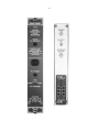
DIMENSIONS NIM-standard single-width module
(1.35 by 8.714 in. front panel) per DOE Report TID20893.
2.5. ACCESSORY
TEST/NORM-OPER/HV DISABLED Front panel
toggle switch permits normal operation when set at
its center position. The switch can be set at Test to
check for response of the warning indications and is
spring-loaded to return to the Norm-Oper position.
The switch can be set at HV Disabled to provide the
interlock output signal that clamps the 743 or 459
output at zero; this setting does not affect the alarm
circuit.
SENSING ELEMENT AND CABLE Custom-built
thermistor probe mounted in a 0.200-in. diameter
stainless steel tube, extends from the dewar cap to
a point about 25% from the bottom of the dewar. A
standard BNC coaxial cable connects the sensing
element to the 729A module.
3
3. INSTALLATION
CAUTION
This instrument is intended for use with only
ORTEC cryogenic detector systems. ORTEC
does not assume or accept responsibility for
damage caused by failure of this instrument
other than warranty repair of this unit.
3.1. POWER CONNECTION
The ORTEC 729A requires dc power from a
Nuclear-standard Bin and Power Supply such as the
ORTEC 4001/4002 Series. Turn off the power in the
Bin and Power Supply before inserting or removing
modules. The ORTEC series of instruments are
designed so that the bin power supply is not
normally overloaded with even a full complement of
modules installed in the bin. Convenient test points
are provided on the power supply control panel to
monitor the dc voltages and determine that an
overload has not occurred. Each voltage should
read within ±0.5% of its rated output under load.
Just before the module is inserted into the bin,
move the slide switch, available through the left
side panel, from Ship to Use. If batteries are
installed in the module, the warning signal will occur
and will continue until bin power has been applied,
the sensor probe has been connected, and the
sensor is immersed in liquid nitrogen. When the
729A is to be used in an ORTEC Delphi system, it
is furnished without internal batteries; the switch
available through the side panel should be set at
Use whether batteries are included or not.
3.2. SIGNAL CONNECTION
The liquid nitrogen level sensor must be connected
to the Sensor connector on the rear panel of the
729A. Use the standard coaxial cable with BNC
connectors that is furnished for this purpose. The
sensor connector on the probe is located on the
side of the fill collar on ORTEC Models 80, 81, and
84, or in the center of the dewar cap on ORTEC
Models 85 and 86.This cable may be run with the
cable bundle along with the preamplifier power and
signal cables.
3.3. DETECTOR BIAS SUPPLY
CONNECTION
Connect a coaxial cable from the Interlock Output
on the 729A rear panel to the Remote Shutdown
connector on the 743 or 459 rear panel.
3.4. INITIAL CONTROL SETTING
Set the front panel toggle switch of the 729A at
Norm-Oper when the system has been connected
and the bias supply is to be operated. When the
bias supply can be used, the HV Enable monitor
light on the 729A lights to show the condition.
CAUTION
Never allow an alarm signal in the 729A to
continue without correction.
4
4. OPERATING INSTRUCTIONS
4.1. INITIAL SETUP
4.2. REFILLING DEWAR
During installation, the alarm circuit will be
activated under normal conditions. If the internal
batteries are included in the 729A, the alarm will be
continuous from the time the Ship/Use switch is set
at Use until power is applied to the bin and power
supply in which the module is installed; the alarm
will continue on an intermittent basis. When the
sensor is then immersed in liquid nitrogen and its
cable is attached to the rear of the 729A module,
the alarm should be turned off unless the Balance
Adj control needs adjustment. When all conditions
are correct, the Balance Adj control can be adjusted
until the warning signal stops. The control was
adjusted at the factory just prior to shipment and
should not normally require any readjustment at the
time of installation.
If the buzzer alarm and light indicate intermittently,
at about 1 Hz, set the front panel toggle switch at
HV Disabled and refill the dewar with liquid nitrogen
immediately. The warning signal will continue until
the liquid nitrogen level is again above the sensor
location in the dewar.
If internal batteries are not included in the module,
the alarm will be activated intermittently when
power is furnished from the bin and power supply
and will continue until all conditions are correct.
The front panel toggle switch on the 729A can be
set at HV Disabled initially to inhibit operation of the
743 or 459 bias supply until the recommended
delay interval has elapsed following addition of
liquid nitrogen into the dewar. See the instructions
for the detector to determine how long this delay
interval should be.
After the sensor has been immersed in liquid
nitrogen, the alarm condition will be discontinued.
Then, after the required delay interval following the
refill (typically 20 minutes), return the toggle switch
to its center Norm-Oper setting. The front panel
monitor lights indicate enable or disable conditions
that are furnished to the Interlock Output circuit.
4.3. NORMAL OPERATION
Power should be left turned on for the bin and
power supply in which the 729A is installed. This
maintains the warning system whether the
associated detector is being used or not and
prevents the occurrence of accidental warmups. If
power is turned off for any reason and the internal
batteries are installed in the 729A, the warning
system can still provide a continuous alarm
indication for a period of at least 30 hours.
When desired, the toggle switch can be set at Test
to check the responses of the alarm circuit. This will
not interrupt the high voltage enable condition, but
it will sound the buzzer and light the HV Disabled
indicator LED. When the switch is released, it
returns to the center Norm-Oper setting. A small dip
in the high voltage level should occur when the
switch returns to its Norm-Oper setting.
5. MAINTENANCE
The 729A Liquid Nitrogen Level Monitor should
require no regular maintenance other than
replacement of components that have failed due to
age. Always ensure that replacement components
are equivalent to the original parts.
This instrument may be returned to the ORTEC
factory at any time for repair service at a nominal
cost. The standard procedure for repair includes the
same extensive quality control tests that are used
for anew instrument. Please contact Customer
Services at the factory, (865) 482-4411, before
sending in an instrument for repair so that the
required Return Authorization Number can be
assigned to the instrument. Include this number on
the shipping carton and on any communication
regarding the instrument so that it will receive
prompt attention at the factory.
5
Bin/Module Connector Pin Assignments
For Standard Nuclear Instrument
Modules per DOE/ER-0457T.
Pin
1
2
3
4
5
6
7
8
9
*10
*11
12
13
14
15
*16
*17
18
19
20
21
22
Function
+3 V
-3V
Spare bus
Reserved bus
Coaxial
Coaxial
Coaxial
200 V dc
Spare
+6 V
-6V
Reserved bus
Spare
Spare
Reserved
+12 V
- 12 V
Spare bus
Reserved bus
Spare
Spare
Reserved
Pin
23
24
25
26
27
*28
*29
30
31
32
*33
*34
35
36
37
38
39
40
*41
*42
G
Function
Reserved
Reserved
Reserved
Spare
Spare
+24 V
- 24 V
Spare bus
Spare
Spare
117 V ac (hot)
Power return ground
Reset (Scaler)
Gate
Reset (Auxiliary)
Coaxial
Coaxial
Coaxial
117 V ac (neutral)
High-quality ground
Ground guide pin
Pins marked (*) are installed and wired in
ORTEC’s 4001A and 4001C Modular System
Bins.