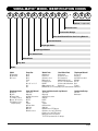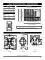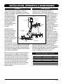
1
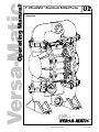
Operating Manual
Versa-Matic
2" Ultra-Matic™ Aluminum Bolted Pump
U2
• Aluminum
®
Versa-Matic® • P.O. Box 1568 Mansfield, Ohio 44901-1568 USA • PN (419) 526-7296 • Fax (419) 526-7289
www.versamatic.com
VMU2ALB0409
Operating and Service Manual
Model U2 2" Aluminum Bolted Pump
Table of Contents
Warnings, Cautions & Notices .................................................. 1
Model Numbers Identification .................................................... 2
Specifi cations & Performance .................................................. 3
Installation, Operation & Maintenance ...................................... 4
TroubleShooting ....................................................................... 5
Parts List .................................................................................. 6
Pump Drawing, Exploded View ................................................. 7
Pump Drawling, Detailed View .................................................. 8
Materials, Temperature Limits & Compatablity ......................... 9
Product Warranty .................................................................... 10
Pumper Parts ......................................................................... 11
Declaration of Conformity ....................................................... 12
Notes ....................................................................................... 13
®
WARNINGS, CAUTIONS & NOTICES
Please read all cautions, warnings and notes
completely before installation and start-up.
It is the responsibility of the purchaser to retain this
manual for reference. Failure to comply with the
recommendations stated in this manual may damage
the pump and void the factory warranty.
WARNINGS
To prevent static sparking the pump, piping,
valves, and containers must be grounded. Fire
or explosion can occur when handling flammable fluids
and whenever discharge of static electricity is a hazard.
Pump exhaust may contain contaminants that
can cause serious injury. Take precautions
to pipe exhaust away from work area if pumping
chemicals, hazardous or flammable materials.
CAUTIONS
You must check the tightness of all hardware
prior to installation.
Do not exceed the maximum inlet air pressure
as stated on the pump model tag.
Maximum temperature limits are based on
mechanical stress only. Certain chemicals
will significantly reduce maximum safe operating
temperatures. For chemical compatibility and
temperature limits please refer to the Chemical
Resistance Guide.
Disconnect the compressed air line to the
pump and allow all air pressure to bleed
from pump prior to performing any maintenance
on the pump. Disconnect all intake, discharge and
air lines. Drain the pump and dispose of fluid into a
suitable container.
Check temperature limits for all wetted
components when choosing pump materials.
Temperature limits may vary depending on the material.
All operators of the equipment should
be properly trained to ensure safe working
practices.
The process fluid and cleaning fluids must be
chemically compatible with all wetted pump
components. Please refer to the Chemical Resistance
Guide for additional information.
Never allow the piping system to be supported
by the pump manifolds or valve housing.
These components are not designed to support
structural weight and pump failure may result..
Thoroughly flush pump before installing into
process lines. FDA and sanitary approved
pumps should be cleaned or sanitized before use.
Noise levels can exceed 85 dBA.
Always wear ear and eye protection when
operating or repairing pumps.
NOTICES
Blow out air line for at least 15 seconds
before attaching to pump to make sure that all
debris is removed. Use an in-line air filter.
Compressed air should not be applied to
the exhaust port. If this happens the pump will
not function.
Clamp style pumps fitted with PTFE or XLTPE
come standard from the factory with expanded
PTFE liquid chamber gaskets. PTFE gaskets cannot
be reused.
Before disassembly of clamp band pumps,
mark a line from each liquid chamber to its
corresponding air chamber. This will ensure proper
alignment when reassembling.
Tighten both outer pistons at the same
time to ensure a tight fit when installing
PTFE diaphragms. See torque settings for additional
details.
The pump does not require continuous
lubrication.
Page 1
VERSA-MATIC® MODEL IDENTIFICATION CODES
X X X X X X X X X X - X X X
Options (if applicable)
Revision Level
Construction Design
Valve Seat Material/Valve Seat O-ring Material
Valve Ball Material
Diaphragm Series
Diaphragm Material
Non-Wetted Parts
Wetted Parts
Pump Size
Model
Model
E Elima-Matic
U Ultra-Matic
V V-Series
Pump Size
6 1/4"
8 3/8"
5 1/2"
7 3/4"
1 1"
4 1-1/4" or 1-1/2"
2 2"
3 3"
Wetted Parts
A Aluminum
C Cast Iron
S Stainless Steel
H Hastelloy C
P Polypropylene
K PVDF
G Groundable Acetal
B Aluminum (screen mount)
Non-Wetted Parts
A Aluminum
S Stainless Steel
P Polypropylene
G Groundable Acetal
Z PTFE-coated Aluminum
J Nickel-plated Aluminum
C Cast Iron
Q Epoxy-Coated Aluminum
Diaphragm Series
R Rugged
D Dome
X Thermo-Matic
T Tef-Matic (2-piece)
B Versa-Tuff (1-piece)
F FUSION (one-piece
integrated plate)
Valve Ball Material
1 Neoprene
2 Buna-N
3 (FKM) Fluorocarbon
4 Nordel
5 PTFE
6 XL
7 Hytrel
8 Polyurethane
9 Geolast
A Acetal
S Stainless Steel
Valve Seat/Valve Seat O-ring Material
1 Neoprene
2 Buna-N
3 (FKM) Fluorocarbon
4 Nordel
5 PTFE
6 XL
7 Hytrel
8 Polyurethane
9 Geolast
A Aluminum w/ PTFE O-rings
S Stainless Steel w/ PTFE O-rings
C Carbon Steel w/ PTFE O-rings
H Hastelloy C w/ PTFE O-rings
T PTFE Encapsulated Silicone O-rings
Diaphragm Material
1 Neoprene
2 Buna-N
3 (FKM) Fluorocarbon
4 Nordel
5 PTFE
6 XL
7 Hytrel
9 Geolast
Construction Design
9 Bolted
0 Clamped
Page 2
U2ALB SPECIFICATIONS & PERFORMANCE
Specifications
Performance
English
Metric
Flow rate
adjustable to
0-175 gpm
0-662 lpm
Port size
Inlet and Outlet 2" Female NPT (BSP)
Air inlet
0.50" NPTF
Air exhaust
0.75" NPTF
Suction lift* (dry)
Rubber
20'
6.10 m
PTFE
10'
3.05 m
Max. particle size
Diameter
0.43"
11 mm
Shipping weight
Aluminum
75 lbs
34 kg
Displacement Per Stroke, 0.47 Gal. (1.78L)
120
0
Meters
260
240
220
200
180
160
140
120
100
80
60
40
20
0
Feet
120
80
100
40
100
140
AIR CONSUMPTION IN SCFM
AIR PRESSURE IN PSI
160
60
Discharge Head in PSI
80
75
70
65
60
55
50
45
40
35
30
25
20
15
10
5
SCFM M3/HR
20
34
40
68
60
102
80
136
100
170
120
204
140
238
160
272
80
20
60
40
20
0
0
0
20
100
40
60
80 100 120 140 160
Capacity in U.S. Gallons Per Minute
200
300
400
500
Capacity in Liters Per Minute
180
600
200
700
NOTE: For U2 pumps fitted with PTFE diaphragms, reduce water discharge figures by 20%.
Suction lift is reduced to 10' (3.05m) dry and 20' (6.10m) wet.
CAUTION: Do not exceed 125 psig (8.5 bars) air supply or liquid pressure.
Dimensions
17.69
449
24.88
632
10.44
265
Ø13.13
333
13.81
351
22.38
568
10.5
267
9.00
229
19.31
491
26.44
672
Ø.50
13
2.50
64
Inches [mm]
FRONT VIEW
SIDE VIEW
BOTTOM VIEW
Consult factory for certified drawings.
Page 3
INSTALLATION, OPERATION & MAINTENANCE
Installation
The pump should be mounted in a vertical
position. In permanent installations, the pump
should be attached to plant piping using a flexible
coupling on both the
intake and discharge
connections to reduce
vibration to the pump
Air Connection
and piping. To further
reduce vibration, a
surge suppressor next
to the pump may
be used.
Suction pipe size
AODD PUMP
should be at least the
same diameter as the
inlet connection size,
Manometer
even larger if highly
Flexible
Connection
viscous fluid is to be
pumped. If suction hose Fluid
Inlet
is used, it must be of a
Shut Off Valve
non-collapsible
Union or Pipe Flange
Connection
reinforced type.
Discharge piping should
be of at least the same diameter as the discharge
connection. It is critical, especially on the suction
side of the pump, that all fittings and connections
are air tight or pumping efficiency will be reduced
and priming will be difficult.
Make certain the air supply line and connections
and compressor are capable of supplying the
required pressure and volume of air to operate
the pump at the desired flow rate. The quality of
the compressed air source should be considered.
Air that is contaminated with moisture and dirt
may result in erratic pump performance and
increased maintenance cost as well as frequent
process “down time” when the pump fails to
operate properly.
Pump Operation
The pump is powered by compressed air.
Compressed air is directed to the pump air
chamber by the main air valve. The compressed air
is separated from the
Air Exhaust
fluid by a membrane
called a diaphragm.
Pulsation Dampener
The diaphragm in turn
Discharge Pressure
applies pressure on
Gauge
Flexible
the fluid and forces it
Connection
out of the pump
Fluid
Discharge
discharge. While this is
occurring, the opposite
Shut Off Valve
Union or Pipe Flange
air chamber is
Connection
depressurized and
exhausted to
Flexible
atmosphere and fluid
Separator
Connection Filter
is drawn into the pump
suction. The cycle again
repeats, thus creating a
Air Stop Valve/
Needle Valve
constant reciprocating
Pressure-reducing
Valve
action which maintains
Air Exhaust Muffler
flow through the pump.
The flow is always in
through the bottom
suction connection and out through the top
discharge connection. Since the air pressure acts
directly on the diaphragms, the pressure applied to
the fluid roughly approximates the air supply
pressure supplied to the main air valve.
Recommended Piping Connections
Pump Size
1/4"
3/8"
1/2"
1"
1-1/2"
2"
3"
Minimum Air Line Size
1/4"
1/4"
1/2"
1/2"
1/2"
1/2"
3/4"
Minimum Suction Line Size
1/4"
3/8"
1/2"
1"
1-1/2"
2"
3"
Page 4
TROUBLESHOOTING
Symptom
Pump cycles once
Potential Cause(s)
1 Incorrect pilot o-ring placement
2 Inner diaphragm plate installed backwards
3 Deadhead (system pressure meets or exceeds
air supply pressure)
4 Air valve or center block gaskets installed incorrectly
Recommendation(s)
1 Reinstall pilot o-rings in correct positions
2 Reinstall inner diaphragm plate correctly
3 Check system for pressure ratio to pump
4 Install gaskets with holes properly aligned
Pump will not operate
1
2
3
4
5
6
7
8
Pump is over lubricated
Lack of air (line size, PSI, CFM)
Worn o-rings
Wrong type of lubrication (attack on o-rings)
Debris in air valve
Clogged manifolds
Incorrect o-ring placement
Deadhead (system pressure meets or exceeds
air supply pressure)
1
1
2
3
4
5
Cavitation on suction side
Valve ball(s) not seating properly or sticking
Valve ball(s) missing (pushed into chamber)
Valve ball(s)/seat(s) damaged or attacked by product
Clogged suction line
1
2
Pump cycles and will not
prime or flow
2
3
4
5
6
7
8
3
4
5
Pump running
sluggish/stalling
Product leaking through
exhaust
1
5
6
Over lubrication
Icing
Clogged manifolds
Deadhead (system pressure meets or exceeds
air supply pressure)
Cavitation on suction side
Lack of air (line size, PSI, CFM)
1
2
3
Diaphragm failure, or diaphragm plates loose
Diaphragm stretched around center hole or bolt holes
Excessive air supply pressure
1
1
2
3
4
2
3
4
5
6
2
3
Set lubricator on lowest possible setting or remove
• Elima-Matic is designed for lube free operation
Check the air line size and length, compressor
capacity (HP vs. cfm required)
Replace o-rings
Check compatibility of o-rings with lubrication
Clean air valve/filter
Clean suction or discharge manifolds/piping
Reinstall o-rings in correct position
Increase air supply pressure
Check suction condition (move pump closer to product)
Clean out around valve ball cage and valve seat area
• Replace valve ball or valve seat if damaged
• Use heavier valve ball material
Worn valve ball or valve seat
• Worn fingers in valve ball cage (replace part)
Check Chemical Resistance Guide for compatibility
Clean suction manifold and/or piping
Set lubricator on lowest possible setting or remove
• Elima-Matic is designed for lube free operation
Clean or replace exhaust muffler
Clean manifolds to allow proper air flow
Check system to locate deadhead (equilibrium)
• Increase air supply pressure
Check suction (move pump closer to product)
Check the air line size, length, compressor capacity
Replace diaphragms, check for damage and ensure
diaphragm plates are tight
Check for excessive inlet pressure or air pressure
• Tighten bolts to recommended torque
Check Operating Manual for recommendations
Premature diaphragm
failure
1
2
3
4
5
6
7
Cavitation
Excessive flooded suction pressure
Misapplication (chemical/physical incompatibility)
Wrong type of lubrication (attack on air side)
Incorrect diaphragm plates or plates on backwards
Incorrect shaft with corresponding elastomer
Start up at full air pressure
1 Enlarge pipe diameter on suction side of pump
1,2 Move pump closer to product
• Raise pump/place pump on top of tank to reduce
inlet pressure
2 Add accumulation tank or pulsation dampener
as close to the pump as possible
3,4 Consult Chemical Resistance Chart for compatibility
with products, cleaners, temperature limitations
and lubrication
5,6 Check Operating Manual to check for correct part
and installation
7 Start up pump slowly (manually or with Smart Start)
Breaking and bending
shafts
1
2
Build up of solids in water chamber
Loose diaphragm plates
1
2
Flush pump, start pump slow
Tighten diaphragm plates when replacing diaphragms
For additional troubleshooting tips visit us online at www.versamatic.com/products/index.asp
Page 5
U2ALB PARTS LIST
AIR VALVE ASSEMBLY
Item
1
2
3
4
5
6
7
8
9
10
Description
Air Valve Assembly
(Includes items 1-10)
Valve Body
Valve Spool Assembly
Valve Spool U-Cup
End Cap Assembly
End Cap Staple
Staple Retainer
Air Diverter
Valve Insert
Valve Gasket
Valve Cap Screw
Item
15
16
17
18
19
20
21
22
23
24
25
26
27
28
29
30
31
32
33
34
35
36
37
38
Description
Center Block
Air Chamber Gasket
Air Chamber
Air Chamber Bolt
Air Chamber Nut
Air Chamber Washer
Bushing
Pilot Shaft
Pilot Shaft Spacer
Pilot Shaft O-Ring
Stop Nut
Shaft Retainer – Left
Shaft Retainer – Right (not shown)
Shaft Retainer O-Ring
Shaft Retainer Screw
Exhaust Valve
Exhaust Sleeve O-Ring
Retainer Plate Seal
Muffler Plate
Muffler Plate Gasket
Muffler Plate Cap Screw
Muffler Elbow
Muffler
Air Chamber O-Ring
Item
40
41
42
43
44
Description
Main Shaft
Diaphragm Shaft Stud
Inner Diaphragm Plate
Outer Diaphragm Plate
Diaphragm O-Ring
45
Diaphragm
46
Back-up Diaphragm
Item
50
51
52
53
54
55
56
57
58
59
60
61
Description
Water Chamber
Water Chamber Bolt
Water Chamber Washer
Water Chamber Nut
Valve Seat
Valve Ball
Valve Seat O-Ring (not shown)
Discharge Manifold
Inlet Manifold
Manifold Bolt
Manifold Washer
Manifold Nut
Qty
1
Standard: Polypropylene
E200
1
1
2
2
2
2
1
1
1
4
E200A
E200B ASY (Includes U-Cups)
P98-104A
E500D ASY (Includes O-Rings)
E500F
E200L
E200G
E200H
E200J
P24-209
AIR END ASSEMBLY
Qty
Standard: Polypropylene / Aluminum
1
E210
2
E212
2
E211A
12
V302G
2
V354C
12
V302GA
2
E201MB
1
E203A
5
P24-106P
6
P24-107
2
P24-108
1
E201B-L ASY (Includes O-Rings)
1
E201B-R ASY (Includes O-Rings)
2
E201B-5
2
10-050
2
E202 ASY
2
E201M-1
2
E201B-3
1
E201H
1
E200J-1
4
E201G
1
PE201N
1
V20AEM
2
P24-107
DIAPHRAGM ASSEMBLY
Qty
Rugged
Dome
Teflon Bonded
Teflon 2-Piece
1
P24-103
P24-103
P24-102
P24-102
2
N/A
N/A
V221F
V221F
2
V221B
V226B
V221TI
V221TI
2
VB221
VB226
V221TO
V221TO
2
V221D
N/A
N/A
N/A
V224BN V224N
V225BN V225N
2
V224ND V224VT
V225ND V225VT
V224TX
V224TF-FB
V224TPEXL V224TPEFG V225TPEXL V225TPEFG
2
N/A
N/A
N/A
V224TFB
WET END ASSEMBLY
Qty
Aluminum
2
V235FB
16
V251D
16
V302GA
16
V354C
4
V240BN V240N V240ND V240TPEFG V240TF V240VT V240TPEXL
4
V241BN V241N V241ND V241P V241TF V241TPEXL V240TPEFG V241VT V240SS
4
V240T (Use with SV240 and V240A Only)
1
V236FB*
1
V237FB*
12
V251D
12
V302GA
12
V354C
* Add "BSP" for BSP threads.
Page 6
U2ALB EXPLODED VIEW
Torque Settings
Manifold Bolts
Water Chamber Bolts
Diaphragm Plates — Rubber
Diaphragm Plates — PTFE
Air Valve Cap Screws
Muffler Plate Cap Screws
Air Chamber Bolts
35 ft-lbs (47 N-m)
35 ft-lbs (47 N-m)
65 ft-lbs (88 N-m)
65 ft-lbs (88 N-m)
25 in-lbs (2.8 N-m)
30 in-lbs (3.4 N-m)
20 ft-lbs (27 N-m)
57
55
See Detail A: 59
Air Valve
Shown with Versa-Rugged Diaphragms
See Detail D for Versa-Dome Diaphragms
See Detail E for PTFE Bonded Diaphragms
See Detail F for PTFE 2-Piece Diaphragms
17
16
54
15
See Detail C:
Exhaust Valves
29
26
40
32
38
See Detail B:
Pilot Shaft
18
52 53
19
42
34
51
43
45
44
33
35
50
36
37
60
61
58
Page 7
U2ALB DETAIL VIEWS
Detail A
Detail B
Air Valve Assembly
Pilot Shaft Assembly
6
5
10
1
2
3
25
8
4
22
24
23
7
9
Detail C
Detail D
Exhaust Valve Assembly
Versa-Dome Diaphragms
42
45
21
40
31
28
30
43
Detail E
Detail F
PTFE Bonded Diaphragms
PTFE 2-Piece Diaphragms
45
45
42
43
46
42
40
40
41
41
43
Page 8
MATERIALS, TEMPERATURE LIMITS & COMPATIBILITY
Materials of Construction — Pumps
®
MODEL
Acetal
E6 (1/4")
■
Aluminum
Cast Iron
Hastelloy C
Polypropylene
PVDF
■
■
●
●
●
●▲
●▲
●
●
●▲
●▲
●
E8 (3/8")
E5 (1/2")
●
●
Stainless Steel
E7 (3/4")
●
E1 (1")
●
E4 (1-1/4" – 1-1/2")
■
■
●■
●
●
●■
E2 (2")
●■
●■
●■
●
●
●■▲▼
E2-FV (2")
■
E3 (3")
●■
■
●■
●
●
●■
● Bolted Construction
■ Clamped Construction
▲ Split Manifold Model Available
▼ High Pressure Model Available
DIAPHRAGMS
●
●
●
VALVE BALLS
●
●
●
●
●
●
VALVE SEATS
VALVE SEAT O-RINGS
●
●
●
Temperature Limits
NEOPRENE
0°F (-18°C) to +200°F (93°C)
BUNA-N
+10°F (-12°C) to +180°F (82°C)
NORDEL
-60°F (-51°C) to +280°F (138°C)
(FKM) FLUOROCARBON
-40°F (-40°C) to +350°F (176°C)
PTFE
+40°F (+4°C) to +220°F (105°C)
POLYURETHANE
+10°F (-12°C) to +170°F (77°C)
SANTOPRENE (TPE XL)
-20°F (-29°C) to +300°F (149°C)
PFA
-20°F (-29°C) to +300°F (149°C)
FDA HYTREL
-20°F (-29°C) to +220°F (104°C)
●
NOTE: These are average temperatures. Chemicals and solvents can have an
effect on temperature limit
●
(FKM) Fluorocarbon
FDA Hytrel®
Santoprene
(TPE XL)
Encapsulated
Silicone
Thermoplastics
FUSION™
Tef-Matic™
●
●
●
●
●
●
●
●
●
●
●
●
●
●
●
●
●
●
●
●
●
Wetted Material Compatibility
Fluid
Solutions
Numeric
Wetted Section
pH Level Construction Metals
STAINLESS
STEEL
CAUSTIC
14
13
12
11
BASIC
10
9
CAST IRON
8
7
6
ALUMINUM
5
4
CAST IRON
3
2
1
0
STAINLESS
STEEL
ALKALINE
NEUTRAL
METALLIC PUMPS can operate past 212°F (100°C). However, if you are
operating above these limits, consult the factory for assistance.
PLASTIC PUMPS can operate to the following temperature limits:
• ACETAL
32°F (0°C) to 220°F (104°C)
• POLYPROPYLENE
32°F (0°C) to 175°F (79°C)
• PVDF
10°F (-12°C) to 225°F (107°C)
Versa-Tuff ™
PTFE
316 Stainless Steel
Polyurethane
Polypropylene
EPDM
Neoprene
PVDF
ELASTOMERS
Buna-N
Aluminum
Diaphragms, Valve Balls, Valve Seats & Valve Seat O-rings
ACID
Page 9
VERSA-MATIC®, INC. PRODUCT WARRANTY
Versa-Matic Pump, Inc. (“Versa-Matic”) warrants to the
original end-use purchaser that no product sold by VersaMatic that bears a Versa-Matic brand shall fail under
normal use and service due to a defect in material or
workmanship within five years from the date of shipment
from Versa-Matic’s factory. Versa-Matic brands include
ELIMA-MATIC®, TEF-MATIC®, THERMO-MATIC® and
FUSION™.
If Versa-Matic determines that a product bearing a VersaMatic brand has failed under normal use and service
due to a defect in material or workmanship within the
warranty period for such product, Versa-Matic will repair
or replace such product at no charge to the original enduse purchaser. The determination to repair or replace shall
be made by Versa-Matic in its sole discretion. The repaired
or replacement product shall be shipped to the original
end-user purchaser freight collect unless the original enduser purchaser makes other arrangements for shipment.
The original end-user purchaser shall bear all risk of loss
or damage during shipment. Repair or replacement does
not extend the original warranty period for a product, and
any warranty repair or replacement is warranted only for the
balance of the original warranty period.
Statements and data relating to products on Versa-Matic’s
website and in promotional marketing and technical
literature and materials are not intended to define the
performance of any product under actual conditions or
when used for specific applications, are not warranties, and
should not be relied upon in determining the performance
of products under actual conditions or the suitability of
products for specific applications.
The above warranty and repair or replacement obligation
does not apply to or include:
• Any product that is not sold by Versa-Matic as new
• Any accessory or other product that does not bear
a Versa-Matic brand
(In the case of such products,
any warranty is limited to a pass through to the original
end-use purchaser of any warranty received from
the manufacturer to the extent such pass through is
permitted by the manufacturer)
• Any product that fails other than during normal use and
service or that fails outside the warranty period for such
product
• Normal wear and tear
• Any product that Versa-Matic determines (a) was
tampered with, disassembled, repaired, modified or
altered without the prior written authorization of VersaMatic (b) damaged during or after shipment (c) used to
pump material that the product was not designed to pump
or otherwise used for a purpose or under conditions
that differ from those for which it was designed (d) not
properly maintained or operated or otherwise misused or
(e) subjected to abnormal use or service.
• Any party other than the original end-use purchaser
• Field repair, removal, reinstallation, labor, freight or other
similar items
To be eligible for warranty repair or replacement, the original
end-use purchaser must notify Versa-Matic of the product
failure in writing within the warranty period for such product
and, if requested by Versa-Matic, the product must be
promptly returned for inspection, freight prepaid, to either
Versa-Matic’s factory at 800 North Main Street; Mansfield,
OH 44901 or to a Versa-Matic authorized distributor. The
original end-user purchaser must also promptly provide
Versa-Matic or its authorized distributor with all such
information as either of them may request concerning the
maintenance, operation, use and failure of any product
that is claimed to have failed due to a defect in material or
workmanship. Return of a product to Versa-Matic’s factory
requires a Return Goods authorization (RGA) from VersaMatic, and the RGA No. must be included with the returned
product. The original end-user purchaser shall bear all risk
of loss or damage during shipment.
THIS PRODUCT WARRANTY IS VERSA-MATIC’S
SOLE AND EXCLUSIVE WARRANTY AND IS IN
LIEU OF ALL OTHER WARRANTIES, EXPRESS OR
IMPLIED, INCLUDING, BUT NOT LIMITED TO, ALL
WARRANTIES OF MERCHANTABILITY AND FITNESS
FOR A PARTICULAR PURPOSE, ALL OF WHICH
OTHER WARRANTIES ARE EXPRESSLY EXCLUDED.
THE RIGHTS AND REMEDIES UNDER THIS PRODUCT
WARRANTY ARE THE SOLE AND EXCLUSIVE RIGHTS
AND REMEDIES AGAINST VERSA-MATIC WITH
RESPECT TO ALL PRODUCTS. EXCEPT FOR THE
SPECIFIC LIABILITIES AND OBLIGATIONS PROVIDED
UNDER THIS PRODUCT WARRANTY, VERSA-MATIC
SHALL HAVE NO LIABILITY OR OBLIGATION WITH
RESPECT TO ANY PRODUCT.
UNDER NO CIRCUMSTANCES SHALL VERSA-MATIC
HAVE ANY LIABILITY FOR ANY CLAIM, LOSS,
DAMAGE, INJURY, LIABILITY, OBLIGATION, COST OR
EXPENSE THAT DIRECTLY OR INDIRECTLY RELATES
TO OR ARISES OUT OF THE USE OR FAILURE OF
ANY PRODUCT OR ANY LIABILITY FOR INDIRECT,
SPECIAL, PUNITIVE OR CONSEQUENTIAL DAMAGES,
INCLUDING, BUT NOT LIMITED TO, LOSS OF SALES,
LOSS OF PROFITS, LOSS OF MATERIAL BEING
PUMPED, DOWN TIME, LOSS OF PRODUCTION, LOSS
OF CONTRACTS, OR DAMAGE TO REPUTATION OR
GOOD WILL, WHETHER OR NOT VERSA-MATIC WAS
AWARE OF OR ADVISED OF THE POSSIBILITY OF
SUCH DAMAGES.
IN ANY EVENT, VERSA-MATIC’S LIABILITY IN
CONNECTION WITH ANY INDIVIDUAL PRODUCT
SHALL BE LIMITED TO THE ORIGINAL PRICE PAID TO
VERSA-MATIC FOR SUCH PRODUCT.
No Versa-Matic authorized distributor or other person
is authorized to modify this Product Warranty or impose
any liability or obligation on Versa-Matic other than as
expressly provided herein.
Rev February 2009
Page 10
PUMPER PARTS®
The Only Difference is the Price.
A division of Versa-Matic Pump Company, Pumper
Parts is your single source for Air-Operated Double
Diaphragm (AODD)
pump parts. The
company was formed
to meet the demands
for faster delivery of
replacement parts at
competitive prices.
Pumper Parts
is a global supplier of
quality replacement
parts that fit ARO®,
Wilden®, and Yamada®
air-operated double
diaphragm pumps.
Pumper Parts serves
customers all over
the world in a variety
of markets, including
chemical, paints &
coatings, food processing, pharmaceutical,
construction, mining, utilities, pulp & paper, metal
finishing, and general industrial. A worldwide
network of fully-stocked distributors and an
extensive staff of qualified professionals are
committed to supporting these customers. Pumper
Parts is housed in a
state-of-the-art facility to ensure that proper stock
levels are maintained.
The Pumper Parts Promise
All Pumper Parts products are:
• Engineered to perform
as well as or better than
OEM parts —
guaranteed
• Manufactured to meet
or exceed the highest
quality standards in
the industry
• Honored with the same
repair parts warranty
as the OEM
• Priced competitively
— providing savings
and value
Pumper Parts Tools
The Pumper Parts
website helps you find
the parts you need fast and efficiently by allowing
searches by product number or description.
Additionally, a Chemical Compatibility database
is provided so that you can quickly find what
materials are most compatible with a variety of
liquids.
Pumper Parts and its products are not affiliated with any of the original equipment
manufacturers referenced herein. All original equipment manufacturers’ names, colors,
pictures, descriptions and part numbers are used for identification purposes only.
Pumper Parts® is a registered trade name of IDEX Corporation. All other trademarks,
registered trademarks and product names are the property of their respective owners.
PUMPER PARTS
A Unit of IDEX Corporation
800 North Main Street, P.O. Box 1568
Mansfield, OH 44901-1568
Tel: 419-526-7296
Fax: 419-526-7289
www.pumperparts.com
[email protected]
Page 11
DECLARATION OF CONFORMITY
DECLARATION DE CONFORMITE • DECLARACION DE CONFORMIDAD • ERKLÄRUNG BEZÜGLICH EINHALTUNG DER VORSCHRIFTEN
DICHIARAZIONE DI CONFORMITÀ • CONFORMITEITSVERKLARING • DEKLARATION OM ÖVERENSSTÄMMELSE
EF-OVERENSSTEMMELSESERKLÆRING • VAATIMUSTENMUKAISUUSVAKUUTUS • SAMSVARSERKLÄRING
DECLARAÇAO DE CONFORMIDADE
MANUFACTURED BY:
FABRIQUE PAR:
FABRICADA POR:
HERGESTELLT VON:
FABBRICATO DA:
VERVAARDIGD DOOR:
TILLVERKAD AV:
FABRIKANT:
VALMISTAJA:
PRODUSENT:
FABRICANTE:
®
VERSA-MATIC®
IDEX AODD, Inc.
800 North Main Street
Mansfield, OH 44902 • USA
Tel: 419-526-7296
Fax: 419-526-7289
PUMP MODEL SERIES: E1 SERIES, E2 SERIES, E3 SERIES, E4 SERIES, E5 SERIES,
E7 SERIES, E8 SERIES AND U2 SERIES
98 / 37 / EC
This product complies with the following European Community Directives:
Ce produit est conforme aux directives de la Communauté européenne suivantes:
Este producto cumple con las siguientes Directrices de la Comunidad Europea:
Dieses produkt erfüllt die folgenden Vorschriften der Europäischen Gemeinschaft:
Questo prodotto è conforme alle seguenti direttive CEE:
Dir produkt voldoet aan de volgende EG-richtlijnen:
Denna produkt överensstämmer med följande EU direktiv:
Versa-Matic, Inc., erklærer herved som fabrikant, at ovennævnte produkt er i overensstemmelse med bestemmelserne i Direkktive:
Tämä tuote täyttää seuraavien EC Direktiivien vaatimukstet:
Dette produkt oppfyller kravene til følgende EC Direktiver:
Este produto está de acordo com as seguintes Directivas comunitárias:
This product has used the following harmonized standards to verify conformance:
EN 809
Ce materiel est fabriqué selon les normes harmonisées suivantes, afin d’ en garantir la conformité:
Este producto cumple con las siquientes directrices de la comunidad europa:
Dieses produkt ist nach folgenden harmonisierten standards gefertigtworden, die übereinstimmung wird bestätigt:
Questo prodotto ha utilizzato i seguenti standards per verificare la conformita´:
De volgende geharmoniseerde normen werden gehanteerd om de conformiteit van dit produkt te garanderen:
För denna produkt har följande harmoniserande standarder använts för att bekräfta överensstämmelse:
Harmoniserede standarder, der er benyttet:
Tässä tuotteessa on sovellettu seuraavia yhdenmukaistettuja standardeja:
Dette produkt er produsert i overenstemmelse med fløgende harmoniserte standarder:
Este produto utilizou os seguintes padrões harmonizados para varificar conformidade:
AUTHORIZED / APPROVED BY:
Approuve par:
Aprobado por:
Genehmigt von:
approvato da:
Goedgekeurd door:
Underskrift:
Valtuutettuna:
Bemyndiget av:
Autorizado Por:
03/02/2009 REV 02
DATE: March 04, 2009
Dave Roseberry
Engineering Manager
Authority: Quality Manager
FECHA:
DATUM:
DATA:
DATO:
PÄIVÄYS:
CE
VMQR 044FM
Page 12
Ultra-Matic™, Versa-Dome®, Versa-Matic®, Versa-Tuff® and Versa-Rugged VR™ are registered tradenames and trademarks of IDEX Corporation.
VERSA-MATIC®
A Unit of IDEX Corporation
800 North Main Street, P.O. Box 1568
Mansfield, OH 44901-1568
(419) 526-7296
Fax: (419) 526-7289
www.versamatic.com
©2009 IDEX Corporation
VMU2ALB0409