1
Film-Tech
The information contained in this Adobe Acrobat pdf
file is provided at your own risk and good judgment.
These manuals are designed to facilitate the
exchange of information related to cinema
projection and film handling, with no warranties nor
obligations from the authors, for qualified field
service engineers.
If you are not a qualified technician, please make no
adjustments to anything you may read about in these
Adobe manual downloads.
www.film-tech.com
Service Manual
www.cineinfo.co.uk
www.cinephoto.co.uk
FA6E
II{TRODUCTION
3l4-l: PRINCIPLESOF OPERATIONS
l-l lntroduction.
l-2 MechanicalSystem
l-3 ElectricalSystem
l-4 SoundSystem
.. .. 15
..-.-.t5
. .. ." .. 15
.-. ts
3 l4-2; SERVICEPROCU,DURIjS
2-l Precautions..
2-2 ToolsAndTestEquiprnent
2-3 LubricantsAndLubricationCharts
24 Troubleslrooting Hints .
3143: MODULE REMOVAL AND INSTALLATION
3 - 1C a m T a n k M o d u l e . . .
3-2 AmplifierModule
3-3 Motar Module
3-4 TransformerModule...3-5 Lens Holder And Cate Module
3144: MODULE REPAIR AND ADJUSTMENTS
4-l Cam Tank Msdule -. .
A. Specifications
B. Disassembly
C. Re-Assembly
D. Adjustments
LClawProtrusion
S . C l a w P o s i t i o n A n d F r a.m
. -i.n g
E. ClawReplacement....
F. ChangingShutterBlades
G. StillPictureClutch
.- . . 1?
.....17
...." Ig
...25
........)<
. .. 26...-...26
. . . 26
27
11
21
2&
...-.-2&
.....29
........3u
-.......31
.....- j7
4-2
A.
B.
C.
D.
E.
Amplifier Module
Specifications
PowerSupplyCircuit
AudioAmplifierCircuit
Magneticd"ecordAmplifier
AmplifrerCircuitDiagrams
4-3
AB.
C.
D.
Motor Module
Specihcations- .- 39
... 39
MotarCircuif Diaersm
ConnectorWiringCode
...-..lg
Silent Film Operation Antl 50 * 60Hz Conversion.- . . . . +O
. . .- 33
.,..33
......,.i'
. . . . . . . . . .. . . : . .'. i;
----..i+
4-4 Transformer Module
A . TransforrnerCircuitDi*gram
B, C o n n e c t o r l V i r i n g C o d e
---.41
.- - -.-,- 41
+s Lens Hokler And Gate Module
A. t r i l m G a tAe s s y .
s. F - i l m S h o e a n d L e n s H o l d e r A .s s y
........43
......43
314-5: CENERAL MECH.A,NICALSERVICING AND ADJUSTMENTS
5-l Take-Up Arm
A. kscription -. - -. 47
B. Adjustrnents.........-4j
-1-
PAGE
5-? Supply Arrn
A. Description...
B. Adjustments,.
...,$E
...49
5-3 ReverseProjection
A- Description.B. Adjustments-.
-..-4g
--.4g
54 Lower Loop Setter System
A- Descriptisn--.
B. Adjustments--.
...50
...50
5-5 S€lf Threading Ffiechanism
A. Descriptinn. B. Adjustments....
l) +tSprocketshma*embly...
2) *tFilmguide
3) Retraction of the claw .
4l +ZFilmguide
5) $ound drum rubber pinch roller .
6) Tension.guideandrollerass€mbty
..
7, #2 $procket and shoe assembly
.. ""52
-..--.-55
.....55
-._....55
- - . ., 56
-......56
. . . . 56
. -. -. . ST
. . . . .Sg
5{ Rewind Mechanism
A- Description-.
B. Adiustments....
...,5g
.......S9
5-7 Sound trrum And Flywheel
A. Description-B. Adjustments....
....59
.-.....60
314{: SOUND PICK-UP SYSTEM
6-l Optical Sound Focusing Procedure
A. Description..
B - A l i g n r n e n- t. .
l) Toolsandequipment..
2).Set-upprocedure
3), Soundfocusadjustment.
4)'Buzztrackadjustment.
-:....
6:2 Magnetic Sound Playback System
A. D e s c r i p t i o n
B. A l i g n m e n t
.-'.-..... ..
li. Toolsand.equipmen
- .t
2I Set'up procedure
314-7:LAMPCIRCUIT
?-l LampCircuit
A. Description-..B. Replacementandalignment..
314-8: ELECTRICALSYSTEM
8 - 1E l e c t r i c a l . $ y s t e m
.....;
A. FunctionControlSwitch
B. ElectricalCircuitDiagram
....61
...;-....61
.....61
-.,.61
....61
.....62
..-...63
-..-..6j
.....63
. -. .53
...,65
-..--...f5
...65
.,.....65
...."..65
.."....65
3 r'4-9: SERVICEUPDATESANE MODIFICATIONS
Attachment:CIRCUITDIAGRAMS
*2-
....-67 *79
INTR,SDUCTION
I. This Servire Manual providesthe necessarylnf*rmx{i*ns for th* repair,adiustrnent,and maintenrneeof
ElKl NSTINT-*eriesplniectcrs, madel NST-0,NST.I, NST"?, NST.3, t{T"0, t{T-l, 8{T-?,and NT-3, and
also EX-3000-frlspriesexf,spr fr:r the Xerron lamp nuprply.
?' This rervire manual csntain $ornepart nurnbersfor csnveniencein identificatian'only" Whenordrri*g
replac*rnenLparts, refrr to NST/NT rcpla*ementparts list.
3. ElKl NSTrrSl-1-tntinr
pr*ieclars may in the future tre irnpr*ved or rno*lified.
Il'lodifiettionsmadeafter the i*sueof this manual will be cover*d by ServiceUpdates.
4. A coFy of all of the perrinentcliagramsar€ attashedat the cnd of thi* rnanual.
5. CAUTION! Care rnust be exercisedto areoidelm{rical *hock while Eeruieingthe proiector.
. - ,3 .
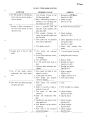
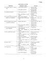
I: ELECTRICAL SYSTEM.
SYMPTO[4
l. Pilot lamp not 0n
2. Pilot lamp on, motor does
not run in "forward " position
{{F.q)
PROBABLECAUS€
1- No power to the AC wall
outlet
2- Defectivepower cord
3. Faulty transformer sr connection
4. Delective pilot lamp
1- Defectivemotor module
2. Defectivcor open motor connections
3. Faulty motor capacitor
4- Switch cam not activating
micro switch #'l
5. Defectivemicro switch #1
6.'Motor thermalswitchopen.
( U L & C S At y p e )
REMEDY
1. Checkoutlet
2. Check& repairor replace
3. Repaircr replace
iSec Sec+41
4- Replace
1. Replaceor repair
{SeeSec4-3}
2. Check& repair,or replace
{SeeSec4-3-C)
3. Check & rep'tace
{SeeSec,4-3}
4. Check& adjust
(SeeSec8-1-A)
5. Check & replace
{SecSec8-1-A)
6, Atlow motor to cool and
check again.
3- Pifot larnp on, motor runs
but the lamp does not come
on in "forward lamp" position { {: rff }
1. Defectivefamp
1. Repface lamp
2. Lamp not seatcdpropsrly
2. Check& reseat
the socket
rarf lP socket
3J- Defective
LrE r TLLIYE lamp
IrLtqtL
3. Repairor replacc
'
4- Check& replace
4- Defectivemicro switch #4 or
#5 on the function control
{SeeSec8-l-A)
5. Open fr.ansfcrrner connection
5, Check&:repair
{SeeSec4-4-B)
6- Replacp
6. Defectivetransforrnermodule
{SeeSdca-a)
4. Pitqt lamp on, motor runs in
"forward",
but not in
"reYersc"position (
tg; )
1. Micro switch it? andlor *3
defective
2. Defectivemotor module
5..Function switch. does not
1. Loose function switch knob
follow the indicatedsequence 2- Loose switch cam
3. Reverse ol
take-up clutch
eann'sinstall$d
*it:
1. Checkor replace
{SeeSec8-1-A}
2. Replace
{SeeSec4-3}
1. Re-lacate and tighten
2. Re-positionand tighten
3. Checkand repair
& 5-3)
SecSec.5-1.,
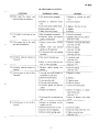
II: SELF-THREADINGSYSTEM
SYMPTOM
PROBABLE
CAUSE
REMEDY
6. #2 film guide {or self-thread
lever)doesnot set the mechanismto thread
1- Cam bracket.is lsose on the
#2 film guide shaft
2. Main interlocking bracket is
binding or not latchingwith
the releasebracket hook
1. Re-positionand tighten
(SeeSec5-5-B4l
7. Check & adiust
(SeeSec5-5-B)
7. Leaderor film is dimpledin
the first few inches bv the
spro.cketteeth
1. Film is inserted with the
sprccket holes opposite the
sprocketteeth
2. Not enough clearance between the sprockelplate and
the fiim shce
3. Film path and #2 sprccket
drive out of alignment
1. Re-insertthe film correctly
4. Film teadertoo sofit
8. Leader iams in the #1 film
guide
9. Tip of the leader enters
underneaththe inner guide
rail
10. Film doesnot threadthrough
the gate,and jams
l. Film leadcr not trimmed
properly
2. End of film is severelycurled,
.
.
1
or twrstedl
3. Very soft'leader
4. +1 film guide shaft looseor
bent
5. Aperture plate assemblyrnisaligned.
-1.
Inner guide rail bent or nof
alignedcorrectly
2. Looseguidc rail screws
3. Film leader end severely
curledor twisted.
1. Film leader not trimmed
properly
2. Leadcr is severely curled or
twisted,or too soft
3- Too much t #'l film shoc
clearance
4. Dirty and obstrusted film
garc
5. lnsufficientside travel af the
inner guiderail
6. Side pressurespring tension
too strong
7. Film shoe is not rctracted
during threading
-5-
2. Check& adiust
(SeeSec5-5-81).
3. Check alignrnent.of the tension guiderollers
(SeeSec5-5-86)
4. Check with anothcr fiIm
leader.
-l
. Trim and repeatthreading
2. Straightenand re-thread
3. R.eplace
leader
4. Re-alignand check.
(SeeSec5-5-82)
5. Rc-alignand chBck
{SeeSec4-f }. ,
l. Af ign or replace
(SecSec4-5)
2. Tighten {SeeSec4-5)
3. Trim and re-thread
1 .T r i m
2. Trim, straightcnor replace
3. Check& adiust
(SeeSec.5-5"81)
4- Clean& check
5. Check& adjust
{SeeSec4-5}
6. Check & adiust
(SeeSec45}
7. Check& adjust
(SeeSec4-5)
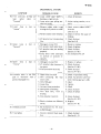
(sELF-THREADt NG SYSTEM)
SYMPTOM
REMEDY
PROTJABLE
CAUSE
'1.
Claw is Rot completely
retracted
1. Check& adjust
{SeeSec 5-5-83}
12^Clicking noise during threading
1. Claw is hitting the rhutt";
blade
1" Check& adiust
(SeeSec5-5-83)
13. Curled film goes over the
loop setter roller
i
1 . L o o p setter position is too
low
2. Severelycurledfilm
1. Check & adjust
(SeeSec54)
2. Straightenthe lcad end
14. Film goes under the #3 film
guideor comesout
1. #2 Film guide defective
2. #3 Film guidedefective
3. #? and #3 film guidesare n+t
aligned
4. Curledfilm
1. Replace
2. Repface
3. Chedk & adiust
{SeeSec5-5-84)
4. Straightenthe leadend
15.Film will not threadoverthe
s*unddrum'
l. Rough surface on the lamp
house casting,restrictingthe
film ravel
2. Rubber pinch roller not completely released from the
sound drum
3. Rubber pinch roller bound
up or eut of alignment
1. Remove & inspect the cait'r*g
guides
11, Chattering
threading
'16.
noise
during
Fifrn stops at the #? sprocket
I. Rough surfacaor restriction
to the film path on the lamp
housecasting
2. #2 spracket reeth or cover
plate loose.
3. Tension guide and roller
assembiyout of alignment
4. #2 sproeketshoeclearanceis
too righr.
17. Film comes sut sf the #2
sprocket shoe
I. #2 sprocket plate is loose
2. #2 sprocketqhoespringweak
or mlssrng
18. Self-threadingmechanismnor
released with a tug on the
film
2. Check& adjust.
(SeeSec5-5-85)
3. Check,adiustand lubrieate
{SeeSec5-5-85)
1. Removethe lamp house
ing and inspect
2.Tighten and re-time
{SeeSeE5-4}
3- Check for correct film feeding from the sound drurn t0
the #? sprocket.
(SeeSec5-5-86)
4. Check and adjust
(SeeSec5-5.87)
1. Tighten and check timing
(SeeSec5-4)
2. Check& replace
{See See 5-5-87)
1. Releasebracket spring is too
weak or broken
2. Releasebracketpin binding
guidenot align19. Film dces nct crosgthe auto1. Auto-take-up
:.
ed properly
take-uPguide
o
n
l
y
)
2.
Fifm twisted,or curled
{NST
i
-6-
1. Check & udiurt
{SeeSec5-5-B)
?. Lubricate pin and adjust
linkage
{SeeSec5-5-B}
1. Check& adiust.
?. Stretch, or replace the fifrn
leader.
lll: MECHANICAL SYSTEM
SYMPTOM
SROBAALE CAUSE
20. Pilot lamp o*, motor run$
but film doesnot advance
21. Film speedis too slow or too
fast
??. Film comes out of ehe
near the sound drum
'J4...
REMEDY
1. Still picture leverengaged
2- Broken or defrctive motor
belt
3. Cam tank plate washerloose
4. Motor pulley loose
5. Main drive belt broken
3. Tighten (SeeSec4-1-B)
4. Tighten
5" Replace
1. Belt is installedincorrectly
?. Incorect motor and shutter
pulleycombination
l. Check & reinstall
2. Replacewith correct pulleys
(SeeSec4-3-D)
1
r.
E',.t-lrFrassg!t
-:6^t
lrltrlta
-^tt^lvttvt
taJ
L:^..f
uf
au-
ing
2- Rubber roller and tension
gukle out of alignment
3. #? sprocket shoe not s€ating
properly
23. Excessivetake-up torque in
"forivardl
1. ReJeasete normal run position
?. Check & replace
"l
- Dry cork of spindleassy
-!.
Remove,lubricatearidadiust
(SeeSec5-5-85l
2. Check& adju+r
{SeeSees-5-86) .
3, Check& adjust
{SeeSec5-5-87}
2. Dirty or sticky take-up
belt, or take-uppulley
1. Lubricate cark
{SeeSec5-1}
2. Clean or rcplzce.
{SeeSec5-l }
24. Excessivetake-up torgue
"rgvel5g"
1. Reverse clutch spring
str$ng
l. Check& adjust
{SeeSec 5-3}
25. Take-up Foor cr not at all in
"forward"
1. Take-up,armbelt broke*, or
stretched,or oily belt.
?. Defectiveball bearing.
3- Lsose spindleshaft
4- Take-uppulley biading
5" Excessivegreasr-on take-up
pufley
6. Clutch cam defective.
X. Replaceor cle+$.
7, Tos loosefilm on thetake-up
reel
26- Take-up poor or not at all in
"fgveFsett
i. Broken or $retched or oily
supply arrnbelt
?. Reversebelt brakenar oily
3. Clutch cam nct engaging
4. Reverseciutch spring weak
-7-
?. Replace.
3. Tighten screw.
4. Clean or rbphce
5. Avoid over-lubricatien
6. Check & repface, or reposition clutchcam.
{SeeSec5-l }
7. Check & absorb extra. film
slack.
1- Replace
?. Cleanor replace
3. Check & repair {SeeSec5-3}
4. Tighten knurled nut
{SeeSec5-3}
SYMPTOM
27. Weak back tension of the
supply rsel in "forward"
28- Weak back tension of the
take-up reel in l'revgrse"
?9. Loop lsstter roller sontinr,res
to activate, or activates erraticallyin "forward"
TMECHANTCAL
.PROBAELE
CAUSE
'1.
Reverse clutch cover pulley
binding and clutch cam is not
releasing, or clutch caver
pulley defective
?. Clutch cover pulley has nc
end play on the #'l sprocket
drum shaft.
3. Clutch cam seated ineorrect,
or defective
4. Clutch cam binding between
clutch coyer pulfey and
spacer
1. Drive gear is binding,or has
no end play on the drive
pullby shaft.
2- Clutch cam seatedincorrect,
or bindingbetwcendrive gear
and clutch cov€r assy, or
defectiveclutch cam
3- Drive gedr, ar clutch cover
defective
1. Damagedor paar film
2. Insufficient gear spring tension
r
3. Loop setterl roller in the
wrong position4. #2sprocket plate loose
5'. Lower loop is toc'small
6. Insufficient claw protrusion,
or claw pitch.
7- Brokenclaw
8. Too much take-uptension
REMEDY
l. Check & adjust; or replace{SeeSec5-3}
2- Check & adjust.
{SeeSec5-1}
3. Cbeck & reposition, or replace. {SeeSec5-1}
4. Check& adjust
l. Check& clean,or adjust{SeeSec5-3}
2- Cheek & reposition
(SeeSec5-1)
S.Check & replaee
1. Repair.cr repface
2. Stretchor replace
{See5ec 5-4-B}
3. Relosate& ehdck
{SeeSec54}.
4. Check & {ghte;n
5. Check #2.sp1o.1r*t
timing
Sec
54-B).
{See
6. Check
{SeeSec4-1-DI }
7- Cheek & replaee
8- Check & lubricate take-up
spindlecork
{SeeSec5-1}
9. Adiusl clearance
(SeeSec 5-41
9. Incorrect cldarancebetween
the laop setter gearand main
drive belt
10. Loop setter gear, or main 10- Replace
drive belt defective,or broken
1 I . Insufficient tension of the 11. Stretchor replace.
film shaesprings
-8-
{MECHANTCALSYSTEM)
SYMPTOM
FROBABLE CAUSE
30. Film continues tc .flap
loop
roller
setter
"forwardtt
31, Lower loop
"rgvgrsg"
is
lo*t
1. Loop setter .gear shaft is
binding,or tight in hub.
2. Loop setter gear spring tension too strong
in
1. R*verse rubber roller is rxlt
drivingthe flywheelset collar
2. Reverserubber rsller bt:nding
3. #2 sprocketnot transporting
film.
12. Upper loop . is
"forward"
lost
33. Upper loop
"rcv€rsett
lost
REMEDY
1, Check & lubricate
2. Adiust spring tension,or replace.
l. Check reverie rubber rotler's
function
{SeeSec5-3)
2. Clehn & remove Ifie causeof
binding
3. Check& adjust
{See$ec 5-4}
1. Damaged,or poar film
2.#1 sprocketteeth plateloosc
3. #1 sprocketshoe,notseating
properly.
4- Loop setter roller continues
to activate or actavates erratically.
I
1. Repair.orreplace
2. Check& tighten.
3. Check& adiust.
{SeeSec5-5'81}
4.SeeSymptomNo. 29
in
1. Darnaged,or p+or filrn
2. #1 sprocketshoeclearanceis
too great.
3. Claw protrusicn irteorrect
I. Repair,or replace
2. Check& adjust
(SeeSec5-5-81)
3; Check& adiust
{SeeSec4-1-Dl}
34- Excessivenoise in the film
gate in "forward" with a
godd undamagedfilm
1. Upper lsop too small
?- Film contacting the loop
scttcr roller.
3- Dirty film gate
4. Looseclaw
5. I nccrrect claw'protrusion
6. lnner guide rail binding
7. Film shoe bent, worn or
binding
L Claw poaition incorrect
1. Check #1 sprocket timing
2. Check #? sproqketand laop
settertiming (See$ec 54'B)
3" Clean
4. Tighten
5, ChecR
6. Check & adjust
7. Check & replace
is
9. Weakor broken cam follower
, spring
35. Unsfeadypicture
L Check & adiust
{SeeSec 4-1-D?}
9. Replace
{SeeSec+1-B}
1, See Symptom No- 34, noise
in tl':efilm gate
36. Travel ghost
1. Check& adiust
{SeeSec+1-F}
-$-
SYSTEMI
iMECHANTCAL
SYMFTOM
37. Excessivenoise in
only
PROBABLE
CAU$E
1. Claw positionincorrect
2. Clzw angleis inccrrect
38. I nsufficient framing
1. Claw position incorrect
2. lllorn carn follower {or gliding pin)
REMEDY
1. Check& adjusl
{SeeSec+1-D2}
2.Check& adjust
{SeeSec4-1-E)
1. Check & adiust
{SeeSec4-1-D:}
2. Replace
{SeeSec 4-1-BJ
39. Excessivenoise when thestill
Bisture lever is depressed
T. Motor'pulleymisaligned
2. Shutterpuffeybindingon the
shaft
40. Film transportdoesndt stop
in stitl pictureoperation
l Shutter pulley sslzed
2. Remove, clea$, inspect and
i
lubricate
(SeeSec4-l-G)
:l. Renieive cam tank, clea* &
2. Still picture lever shaulder
screwsloose
lubricatepulley
{SeeSec+1€}
2. Tighten scre!,r/s
{SeeSec4-1-c}
41. Film burns when still picture
lever is depressed
42. No rewind or poor rewind
1. Stitl picture lever not completcly depressed
2. Heat filter misaligned' or
braken
1 . Take-upspindlecork too dry
or tight
2. Bfoken cr stretched or oily
rupply arm belt
3. Defectiverewind gears.
4.8roken rewind arfn t€nsiofi
spring
5. Take-up pulley binding on
the shaft
1. Adjust
1. Fully depress
2. Check,realignor replace
1. Removeand lubricate
(SeeSec5-1)
2. Check and rbplace
3. lnspebt& replace
4. Check & rJeplace
{SeeSec5{}
5- Clcan& lubricate
43. f4oisyrewind
1. Rewind gears nat fully engaged.
2. Worn or defective rewind
gears-
1. Adiustthe gearposition
{SeeSec5-5}
2. Replace
{SeeSec*5}
44. Uneven foeus
1- Dirtl, film gate
2, Fitm shoe binding and not
completely seat€d
3. Inner guider:ailbinding
l. Clean
2.Check & realign
{SeeSec4-5-B}
3. Check
.{SeeSec4-5)
4. Check & adjusr
SeeSec4-5
4. Lensholdermisaligned
*10-
+r
s
-(Ir
i*t
r
= c
=
5--
5'
:e
-{!
.s,
{e
=
e
a
E
5|a
UT
Al
F
3
5
{1i
E
-}
n
E'
6'
=
g
At
I.'
ft
E
r€
G Ers
E
E?
P P o
qt;_
tD
=6
o - .
5 A
si'q
n
at
:r
Bg'
f65j9t
nn-r
T =-:
?
g
fF ;i rS5 :
=-
t
=tl
m I'
r lD
N'
g
;t
ltslr
B
f
g
F
B F$ F
!\'-
f
t-l
.9'!"i {'} r n
IT
I f;s
F d H
F'
ir
.
f
rl =
S
F
!ntsne
=
's
A
fF lr
+
:i
t
4
f
H
X
iB
E
sE l
=
g.
itt
N
=
?
D
v
A
r
}
i-)=
-t
j
=
$
F
H t r : . e He c
3 t 5c t s =n f f i I
o
.tts
09
=
=
Efr { FE
Ro
i
E
- = r' r:!
t(!
.
!
(|i
s-
f;
E-
o
.d -g
yl',r-
f
bH
gff
Oo
FFI-
+
I
I
f)
+
n
=
{
O l -or : +
!*i:
EF-458-45 r$g
g ? = E = 1F€g
.'.o
:E i-"
e
= < g
t t : = i :
-Ei.o
P
=
$-3 *il33[5ig F *
i F * n e f g Fd I
f
= f t t t '
i
a
.f
a
o
tr
t!l
|r,
E
Ilr
5
dr
!EJF
=rt/,
U}
.{
d
m=
5
P
I
7
!L
J o
-
i !
frno3
- E a SFrt'l
* = I € il=
Gl
t,
la
T D 6 B
F r F
:Jrq
f!
F,
c
H
=
. h
I
rs
T'
.t
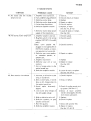
V: SOUNDSYSTEM
SYMPTOM
PROEABLE
CAUSE
4 7 .No sound and the exciter
1. Amplifier is not turnedon.
2.9 pin amplifierplug defective
3. Defectiveexciter lamp
4. Defectiveexciter lamp socket
5. Exciter larnpfuseblown
6. Defectivearnplifiermodule
lamp is not on
T. Defective exciter lamp power
supply of the transformer
48. No sound, exciter lamp is on
49. Poorsoundor low volume
REMEDY
1 . T u r no n .
2. Check & repatr, or replace.
3. Replace
4- Repairor replace
5. Check& replace
6, Reptace,or repair
{SeeSec3-2, & 4-21
7 . Losate & repair, or replace,
(SeeSec44)
l. Amplifier volurneis tao low.
2. Mag/Optswitch in the wrong
position (NST/NT-2,-3models
only)
3.Rear cover sp€aker not
pluggedin {not applicableon
NST/NT-3 models),or extension speakersnot connected4. Defective rear coYerspeaker,
or extension speaker, or
speakeriack.
5. Amplifier fuseblown
6. Defective solar cell of connections
7. Dirt or foreign objcct in the
optical soundlens
8. Defectiveamplifier module
1. Check& adjust.
?. Check& switch
l. Incorrect,ordefectiveexciter
lamp,or soundlens.
?. Dirty exciter lamp, or sound
Iens,or dirt, foreign object in
the optical soundlens
3. Sound optics incorrectly
aligned.
4. Low exciter lamp voltage,or
low AC supply voltage.
1. Check& rbplace
5, Weakor defectivesolarcell.
6. Defective speakers,or poor
speakerconnection
7. Poor film quality
8. Defective amplifier module
-12-
3- Check & connect.
4. Repairor replace.
5. R.eplace
6. Repairor replace
(SeeSec42)
7. Clean.
B. Lscate & repair,or rcplacc
{SeeSec 3-2 & +21
2. Clean,or replace-
3. Check & re-alignsound pickup system {SeeSec6-1}
4. Check & repair amplifier
exciter lamp supply. {SeeSec
4-21.Cheek walI outlct.
5- Replace6- Check & replace
7- Check with anotherfilm.
8. Repair or replace"
{SeeSec3-2, & 4-2}
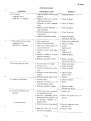
{souNDsYsT€M)
SYMPTOfi'
50. No sound
(magneticonly)
{NST/NT-2,-3 modcls}
5J. Poorsoundor low volume
{magneticonly)
-3 mdets}
{NSTINT-2,
52. Exciter lamp fuse blows
PROBABLECAUSE
1- Mag/Optswitch in the wrong
position.
2. Magnetichead not in contact
with the sound track
3. Defective or dirty rnagneti€
head
4. Maelopt switch defective,or
bad connection
5 - Defectivespeakers,or speaker
connections
6- Defective amplifier module
1. Poor soundtrack?. Dirty, or defectivehead
3. Head not making good contact with the film
4. lncorrect sound head alignment
5- Defective speakers,sr poor
speakerconnection
6. Defectiveamplifier module
1. Excessive
AC line voltage
2. lncorrect fuse
3. Incorrect,ordefectiveexciter
lamp
4. Defectiveexciterlamp power
supply
5" Defectiveexciter lamp socket
53. Amplifier fuse blows-
54. Excessive
amplifier hum
iopticat)
- to be continued-
l. Incorreetfuse
?. lmproper connectianto an
external speakersystem
3. Defectiveamplifiermodule
1. Exciter lamp cover missingor
REMEtrY
1. Check& switch.
2. Check& adjust.
3. Clean,or replace.
4- Check & replace
5- Check & replace6. Repair or replace
SeeSec 4-2 & 3-71
1. Checkwith anotherfilm.
2. Cleanor replace.
3. Adiust
(SeeSec6-2)
4. Align
{SeeSec6-2}
5. Check & replace
6. Repairor replace
{SeeSec 4-2 & 3-2lr
l. Checkwall outlet.
2. Check & replace.
3. Check & repface.
4. Check& repair
(SeeSec4-2)
5. Replace
1. Check& replace
?. Check
3. R,epairor replace
{5ee Sec 4-2 A }-21
l. Installcover
not installed correctly.
2. Incorrect grounding whcrr
connccting the projector to
an external amplifier or
sound system
3. Defectiveexciter lampsupply
4. Defectivc solar cell or connectionsto arnplifier.
.- t3-
?. Check for grourrd loop conditions.
3. Checkvoltageand repair,
(SeeSec4-?!
4- Check& repair
{souND SYSTEM}
SYMPTOM
amplifierhum
54. Excessive
(optical)
- continued-
amplifierhum
55. Exccssivc
{magnetic}
56. Distorted sound
wow & flutter
57. Excessive
PROBABLE
CAUSE
5. Front or rear cover speaker
jacks not insulated from the
chassisproperly
Defective
amplifiermodule
6.
1. Poor film rerording
2. Motor shield not installed
3. lmproper connectaonto an
external amplifier or sound
system.
4. Magnetic head in poor contact with the film.
5. Poor shieldingto the heador
the head coil shorted to the
projector's frame
6- Defectiveamplifiermodule
1 . lncorrectexciter larnp.
2. Exciter lamp covernot completely installed
3. Amplifier module is defective
4. Defectivespeaker
5. Magnetic sound recorded
poorly
6. Optical soundlensnot aligned
correcdy
?. Dirt on the sound drum or
on the solarcell
8. SeeSymptomNo. 57 also.
1. ltubber pinch rollerbinding
2.Sound drum bearings dcfcctive
3. Reverserubberdrive roller in
contact with the set collar
4. Flywheelnot installed
5. Flywheel rubbing on the
power cord
6. fncorrect alignment or tension of the t€nsionguideand
roller assembly
58. Ssund not stabilized
after starting
l - lnsufficient flywheel plate
sprlngtensron
2- Weak rubber pinch roller
spring
*14-
REMEDY
5- Check& repair.
6. Repairor replace
{SeeSec+2 & 3-2)
l. Checkwith anotherfilm.
2.Check & install.
3. Check & re-connectproperly
4. Adlust
(SeeSecG2)
5. Rcpair
6. Repairor replace
{See Scc 4-2 & 3-2l'
l. Check & replace
2. Check& re-install
3. Rcplace
4. Replace
5.Try a known good recording
6. Check & realign
(SeeSec6-1i
7. Check& clcan
8. SceSymptomNo. 57
-1
. Check, clean, lubricate
adjust(SeeSec5-5)
2- Check& replace
{SeeSec5-7)
3. Check& adjust
(SeeSec5-3)
4. Check
5. Check& adjust
6. Check & adjust
{SeeSec 5-5-86)
1. Check& adlust
(SeeSec5-7)
2. Check& replace
{SecSec 5-5-85)
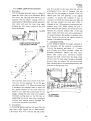
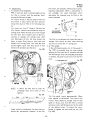
n-
manufactured to meet such regulations,inclqding
the opticn of 50H2, 60H2, 50/60H2 operationPower transftrrmerg vzry aceordangto the voltage
range and also to the various electrical safety
requirements.The secondarywindings of all transformers provide 8V AC to the Pilot Lamp and
Exciter Lamp circuits, 24V AC (HIGH) and 22V
AC {LOW} to the Halogen Prciection Lamp and
40V or 36V AC to the AmPlifier.
{SeeSec.+4 TRANSFORMERMODULE).
Motor OFUOFF and Lamp ON/OFF and reverse
is controlledby the FunctionSwitch which consists
of a Cam and 5 micro switches.
I.2: IIilECHANTCALSYSTEM
The proiection lamp b a Halogcn ELC type 24V
"High-Lorv" position wilt extend
250 watt- The
The ElKl Self-threadingproiector is contrclled by
operatingcorditions.
a single function switch for forward, reverseand the lamp life,dependingupon
: The Hatogen LamP EtL tYPe 24V
NOTE
high-lowlamp positicns.
200W maY also be uscd with some
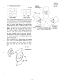
A. T.HEEAD!_\!_Q:
reductionin light outPut.
Threading is accomplishedby s€tting the
is an induction type with capacitor.
motor
The
threading guide lever to thread' function
Motors are available for all the voltage ranges
switch to forward and inserting the fitm
also
i*to the threading channel- The threading above. Optional Synchronoul motor kits are
available for precise film spcedr and tele+ine
mechanism is automatically releasedand
conversions,
engagesthe claw by a light tug of the film
Transformers and motors are simple and easy'toreel.
the
take-up
when attaching ir to
replace modules. AC power cords, line terminals,
B. to[lu4lql Al''tf'
and all other electrical parts are designedto meet
Advance the switch from forward to lamp
the safety reguirementsof the countries listed'
low or high,
l-1: INTRODUCTION
"N" seriesself-threadingprolector is very
The El Kl
"R" s€riesmodel with added
similar to the earlier
improvements such assilent threading, flet response
amplifier, lighter weight, etc. With few exceptions,
"N" series
zuch as color, most parts from the
"R" sries'
substitute direetly into the previous
This manual also coversthe NT manual threading
models when excluding the sectionson the threading mechanism.
C. REVERSE:
To reversethe projector, return the function
"OFF" and then to reverseand
switch to
lamp.
D. REWIND:
To reivindthefilrn,engagethe rewind lever.
Attach the film to the empty supply reel
"Forand advancethe function switch tc
ward".
1-4: SOUND SYSTEM
ElKl "N" seriesmodelsare designatedaccordingto
the sound playback and record capabilitieswith or
without front cover extension speakers.
Optical Playbackonly: Model NST-O'-l
& NT4, -1
NT-2
qEIE4_ann"gr'relg
l!"yLqck;ModelNST-z,
eEq..!4_l$tg1ericRecard
l':t!gy!gg!:
Model N5T-3, NT-3
1-3: ELECTRICAL SYSTEM
Modet NST-I , -2 & -3 and NT-l, NT-? & NT-3 are
built[lKl "N" seriesprojectors are availablein voltages standardwith two {4 ohm, 12.5cm)speakers
'l0V,
and
NT-1
&
2,
NST-I
Models
cover.
front
in the
120V, 2?0V and ?40V. 110/220V
of 100V, I
(8
12-5cm)
otrm,
and 120124fiVdual voltagemodelsars alsoavaifable. & 2 zre atso standard with one
speakerbuilt-in the rear cover.
To comply with electrical safety regulations of
Models NST-0, and NT-0 are standard r,Yithsne
variouscountries,UL (USA), CSA {Canada),VDE
'l2.5cm}
built-in the rear
speaker only {8 ohm,
{Germany), SEV (Switzerland),SAA (Australia},
cQvef.
SEMKO {Sweden},NEMKO {Norwav), FEMKO
The standard amplifier modules for the NST-0
(Finland), DEMK0 (Denmark),specific modelsare
-15*
*
FP
E
-t T
:lE
o 6
F e F
t t
i E E+ = + i
E r E I z
E- #
Er
6iq I
E q E
t r g O _
F
.
-
F
5
=
E
E
o
H
-+r
=-o
tu
E t !
' F+ ' 4-
F q
F,
1
* ,i.
O r P
eci
= Z
E l - 1
Eil
I t
f i f r
I t a r Y
R ' i . t
: 1 : { =
U
A
1F3-'
" E - 5-I! i
E.+
Sx
tr
5 r o
oz.
1U?
:
B =
6'e
o
E
[,]
B
E Eh)
i
E ,
ri
H =a
+ H A
=
t
*ER
- ! !
r 5 .
S F
. J E
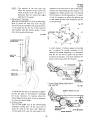
Tsal Nc. 3?0-0tT
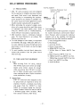
2-1: PRECAUTTONS
CamClawProtrusionTool
1. ElKl "N" seriqsprojectors have been designed
{seesec.4-1-D)
for the ultirnate in simplicity and easeof seryice
and repair. Eaeh screw is very impcrtant, and
gMALL
when servicing or re-assemblingth€ projector,
"v" $oTcH
scfaw$ should not b€ omittd or carelesslyfost.
All screwsshould be firmly tightened to assure
reliable projector operation after re-assembly?. When lubricating the projector's plastie parts,
silicon oil or greaseshould be us€d.Other types
of lubricants may harm plastic partr. Avoid C. T s! _quipment:
using any solvents such as Trichloroethylene,
A limited amount of test equipment is required
which will harm rnost plasticor painted parts.
for routine maintenanceand modular replace3. EIKI projectcrs require a minimum of special
ment. However, vrhen servicing the individual
tsols. The mort important is an ordinary l5O
modules such as the amplifier, the follawing
Phillipsscrewdriver s€t.
equipmentand test films would be essential:
4. To avoid damage to screw heads,it is important
a. Vom {Voltage/Ohmmeter}
to remember the adage"70% push, 3096turn."
b. Oscilloscope
It is also irnportant to selectthe right sizescrew
c. Audio AC VTVM
driver blade. A rule of thurnb is to use the largest
d. Wow & Flutter Meter
blade possible.
e.40slHz SMPTE Test Filrn
possible
electrical shock, always dis5. To avaid
f. 3130t1z Wow & Flutter SMPTE Test
connect the proiector from the power source
Film
g. Mulli FrequencySMPTETest Film
when servicing.
h. 7000H2 Sound FocusSMPTETest Filrn
i. 7000H2 Mag.Azimuth SMPTETest Film
?.?: TffiLS AND TEST EQUIPM€NT
i- Buzz Track SMPTETest Film.
A. Tools:
k. Audio Oscillator
When servicing ElKt "N" series, ordinary
ISO {Phillips type} screwdriversand singlebladed scr'evr drivers should be enough.
(ElKl screwdriver kits, PlN 5615 are available-) A Malex extractor taol is most useful
when replacingthe pins of Nylon connectors
to the transformer or motcr,
B. Speciallcols:
ElKl "N" serieshave been designedso that
no special tools are required to servicethe
projector. However, a common elaw protrusion gauge {Tool No- 32O{1T} is most
helpful for accurately setting the claw protrusion. Standard16mm film may be usedas
a thickness gauge where n€cessary-{Most
filrn is about0.l5mm or -005" thick).
-17-
Apply a few drops after every 500 operatinghours.The items marked yvith * would require more frequent
L.rbrication.
CAUTION:DO NOTOVERLUBRICATEFts.#r
12
frt
E$#
DESCRIPTIOITI
#1 Sprcket Hub
#2 SprocketHub
Duramn GuideRolbrs
Durcon GuldeRollers
*Flubbr PinchRoller
Self-Thred Letler
RubberPinch Eoller
Pivot $heft
Rewind LeverShaft
OampeningRofler
Pivot Shaft
TensionGearArm
Pivot Pin
TensionGeaShaft
SUGGESTEDEIKI
LUERICAHT PART #
Fetrohum
Qif
Petroleum
oil
SiliconeOil
#100
$ilicone Oil
#100
Molybdenum
Dizuffide
Grease
Petrsleum
oil
Petreleum
oil
Petroleum
Oil
htroleum
oil
Petroleum
oil
Silicone Oil
#r00
*#t
Petroleum
SprocketGear&
Worm Gear
oil
*ReyerseRubber Fotler
Petralaum
Shalt
oil
Sound Drum Ball Bearings {Fctory
sealed
56:11
'TEM #
15.
DESCFIPTIOIII
SUGGEETEDHTI
LUBRICAHT PART #
*Take-Up ftrlley Cork
Liner
Loop S€tterSh8ft
6631
Silimne
S25
Groase
Petroleum
16.
5631
oil
1?.
#3 Film GuidePiyotPin Silimne Oil $029
#1Hl
TensionGuide Holler &
SiliconeOil Eg29
18.
BrackatPin
#16
MdyMenum 56i18
19, *Tak*Up Pulley & Shaft
Oiislfide
Greaee
20. *Supply Arm $pindle Shaft Petrol:um
5631
oil
Maly&num
21 EamTank
5Q28
Diqrlfide
Grege
Molybdenum 5632
21-A CamTank Felt
trisr|fide Oil.
(5S281
or Gresse
22.
RewiqdGears'Shaft
SiliconeOil 5629
#100
Flywhrol Hole
Petroleum
8.
5631
oil
24.
Loop Safery Rollar
Siliccne Oil 562.9
5631
fi-
Mein laterlocking 8ra*st
08608Z
26.
ReelGuide BracketHole
5631
5629
ffi?,9
5628
5631
5ql1
8631
5531
5631
5629
-r8-
#loo
Sificone
Grease
Petroleum
oil
5625
5631
ITEM#
27.
za.
29.
30.
suGG€sTED €tKl
DESCFIPTION
ITEI' #
LUBF|CAilT PAET #
ReelGsi& l$re
Petraleum
Fr,lrction $ritrfi Cam
E6gI
31 .
AnchorageFulcrum Pin
O{t
Bracket
Shutter Pulley Bushing
MolyHenum E62B
Disulfide
32_ Function Switdr Shsft
Grease
CamTank Fulerum Pin
Petoleurn
E63l
oil
st.
Loop Safety ffoller Arm
All Ball Bearings
Pin
{Factory Os€OSz
oESzZ
realedl
34.
Clutch Cover Pulhy
oa-g?go.zz
&rshing
o8-626
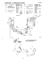
I}ESGRTPTTON
FILM PATH
SUGGESTEDEIKI
LUBfiICATIIT PAflT #
Molybdenum 5628
DisulfHe
Greesc
t*olyMenum 56?8
Disulfide
Grease
$licon
5625
Greare
Fetrcleum
5fr11
oil
I (HUB}
Fry'#z
I lPtNl
6 {Prfit
7 {PtN}
tt
1? (PtXl
3
t6 {ptlfi
Fis.#s
$E LFTTHREABII*GMECHAT*ISiI
{lilain Inerlodring Brrd<et}
"{
- 19-
i )
rj
Fis-#l
CAM TANK hIODULE
CAM TAIIK MODULE& FILM GATE
Fis. #5
io
I
I
I
I
.I t-----]
It":-J
-20-
I
#T SPROCI(€TG€AR A HU8.
CLUTGH COVERPULLEY
fis. #6
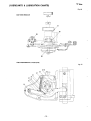
Fe-*r
souttftr trRult|.HuB,
& FLYWH€EL
TAI(E-UP PIJLLEY & SHAFT
Fis' #8
LOOPSETTEF
-21-
Fis-#to
REWINDGEARS& GOT{TflOL
LEVER
TAK€-UP ARM DRIVE
ruLLEY
SUPPLYABM DRIVE PULLEY
TEf{SION GEAB
-22-
Fb.#rr
SUPPLYARI' SPIT{DLE
REVER$E FUBSEF ROLLER
Pltrl
Fi$ #15
RUBER PTNCH
ROLLER
Fis-#18
FUfiCTTOnFOTARYSWITCH F,s.#tt
LOOPSAFEW
ROLLEB AR[tt
-?3-
fe. #2r
24: TROUBLE SH0OTING HINTS
DIOD€S
A. There are four basic steps to trouble_:lrpS{rrg
a. Analyze the symptom
b. Localize the trouble to a functional system
or module
c. Replaceor repair t}lat systemor module
a. lsolate the trouble within the module
b. Locate and repair the specifictrouble
B . CheckingSemiconductorsWirh A VOfi4:
a- Set the ohms scaleto R x 10
b. The forward resistanceshould be low
c- The reyerseresistanceshoutd be high
TRAFISISTORilPN TYPE (2$C.2SD,
FIs.#I9
Fb. #eo
+
/--\
--FtlGH-
tttrlltglgglgl
\_./
+
!
I l.:tNOTE: Farutard and reversr resistanceLOW &
HIGH is only a suggestedquick and easy check
of componentsout of circuit. This test is only
firr shcrted and open junction t€st. A VOM will
not test the quality of a :erni-conductor accurately.
C. lC's are best checked by checking the signat
input and output conditisn. This can be done
by inserting a low level audio tone inta the
MIC jack and the signal path from the input
of 1C-1through lC-2 and to lC-3.
D. Amplifier test cables can be easily made from
locally availableparts. A nine pin miniature
tube socket and mate plug can be wfred as an
extensicn power cable, allowing the amplifier
to be operated away from the projector. The
solar cell and exciter lamp connestion can also
be extended if so desired.
re. #ze
TypicalAmplificrTestSet-Up
o8clLL0SC0PE
SPEAK€R
EIIISITSFUT
-24-
Frs.#23
iIOTOR IfrODULE
CAM TAHK
MOOULE
AMPLIFIERITIOBULE
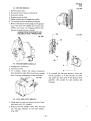
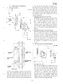
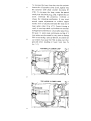
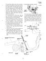
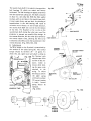
3-l: CAM TANK MODULE
1 . Unplug th€ projector and open the rear cover.
2. Remove the 3 transformer mounting $erews
and unplug the transformer-{SeeSec 34}
3. Removethe motor belt.
4- Remove the main driving belt by releasingthe
tensiongear.
5. Retract the claw by turning the inching knob.
6. Open the lamphouseand remove the lamp and
holder asscmbly by unscrewing the knurled
nut7. Unscrewthe two cam tank mounting screws.
8. Remove the cam tank slowly and carefully.
Care *rould be taken to avoid darnaging the
claw by strikingit againstthe main casting.
9. Re-installation can be done by the reverse
procedure.Care should be taken that the cam
tank worm gear and main drive fiber gear do
not bind. A small amount of gear lash is
required ta prevefit abnormal wear.
10. To check the timing and cla',v adjustments,
refer to Sec.5-1 and 6-3Fis.#24
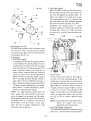
3-2: AMPLIFIER MODULE
1. Removethe flywheel2. Unplug the rsar cover speakercord.
3. Removethe volume, bassand treble knobs.
NOTE: cn magneticmodelsremov€the mag/opr
knob.
4. Unplugthe MT 9 pin plug.
5. Unplug the sslar cell and magneticlezd miniature
plug.
6. Rernovethe two phillips scfe$rg,one at eachend
of the amplifier.
7. The amplifier can now be removedby sliding
out.
8. To re-install, rwerse the procedure above. Be
sure that the indicator on the controls lines up
and all thc connectorsare sccurd.
Fis.#25
q
-xt -
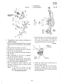
3-3: MOTOR MODULE
Fa.+F28
1. Removemotor belt.
2. Disconnectmotsr.nylon connector(s).
3. Unscrew 3 screws.
4. Removemotor module.
5. Motor modulesare exchangedlesspulley,
6- To re-install, reversethe above procedures.
7- Motors with plasticfan housingsus€theground
strap. NST after S/N l$484, and NT after SlN
18550, with metal fan hcusing t320-121411,
the ground strap hasbeenomitted.
GRO$NbSTRAP
IFORPLASTICFAf{
HOUSIiIGOF EARLYPRODUCTIOIII
Fig. i+z$
Fis.#2C
*)
3-4: TRANSfORMERMODULE
l. Unplugnylon conne€tors.
2. Unscrew3 screws3. To re-install, reversethe above procedures(Careshouldbe taken tfrat the wlresare ro{Jted 3- To re-install ttre film gate assembly,follow the
awayfrom any movingpartsof the projector)"
revers€ procedure- lt is also necessaryto check
and adjust the claw ravel in the aperture plate
assembly. {See section 42 claw position and
framing).
Ft*#Zt
3.5: LENS AND GATE MODULE
1. Swing open the gate and remoyethe lens.{Antitheft screwon U.5.A. models).
2. Remove the two phillips screws {40} securing
the film gate assetnbly to the main casting.
{Fie. #?9}
-?6*
4. tThile holding the shutter blade {a6} slowfy
raise the still picture clutch, releasing the
tension of the clutch spring (12) and shutter
A. Spgcifications
Revolution
blade with hub.
5. Removethe shutter blade and hub arrembly.
24FPS.1440RPM
18 FPS.1080RPM
6. Position the still picture clutch where it exposes
all drree cam tank sover scr€ws {a5). Remove
CamClawProtrusion
MlN. 1.0mm MAX. l.2mm
(.040" to .045")
the screwsand cover plate assembly.
Pitch
7.
The curved plate spring (24) fits over fulcrum
7.67mm
Claw
7.64
control pan. Unscrew the screw {T2} and
remove eurved plate spring.
8.
Unhook the claw leverspring {36i, and remove
NOTE: Tension of Claw Lever Spring is mea*
claw leverassy.{?8)
ured with a tension scale pulling on Cam Claw
9. To remove cam {10} and cam plate {9}, unand the Claw Levrr Spring sffetched to maxiscrevrthe three set screws {l I }.
mum10. To rcnrove cam shaft assy. {4}, remove inching
of C4l!_T'a4 [Fig. #30 & 31]
B. Disarss.mbly
knob {E} and uprm gear (7}.
1.Set the still picture clutch to the still posiaion
11, To replace the cam tank bearings, the inner
with the shutter pulley {50} ratati*g freely,
bearing is pressedan the carn tank shaft and is
2. Unscrew {53} at the end of the cam shaft and
replaced as part of the cam shaft with bearing
shutterpulley {50)assy.
3. Remove shutter pulley {50) and the plate
wa$her(511. Care should be taken not ta loose 12. Clean all the old dried molybdenum grcase
the slim washer {5a} behind the pfate washer.
from the cam rank,
The slim washer is selected where neces$ary
to provide the corect clearancebetween the
Fis. #C,
shutter pulley (50) and the strutter blade and
hub (46).
4-1: CAMTANK MODULE
.
;;::;iil-:"';i**
3
- '.2sks
1'2
#;
:t8
39
-2t *
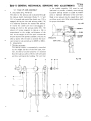
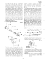
D. Adjustments
1. Claw Protrqliq4
FE-#gt
C. Reassembly
of Cam Tank By ReversingThe
AboveProcedure
1- Makesurecurvedplatespring{2a} is nor iammed
betweenthe endof fulcrumpin (181andwasher
(231.
2. The cam shaft should have no end play3, Worm gear (7) is mounted without any clearance
betweenthe cam tank bearing.
4. No end play is allowed for the ball bearingson
the cam shaft.
5. When overhauli*g the cam tank, it is suggested
that the felt oil pad be replaced.
6. Re'lubricate the carn area with a small amcunt
of molybdenumdisulfide greaseand moisten the
felt with a few drops of rnolybdenumoil.
T.lVhen mounting the shutter bfade and hub
assembly,the hub rnust line up with the mating
hub in the cam tank.
NOTE: In the event the shutter has been
removed from the hub, See Sec. 320It-l-F ChangingShutter Blades.
-?B-
Fic. #34
a. Claw protrusion can be adjustedby the scrcw
(B) on the fulcrurn collar. As the sliding pin
{31} wears, the protrusion will increaserequiring the adjustmentof the protrusion.
Fn #f,1
scRElr fAl
-sREw(al
scaElY lcf
b. Loosen set screw {A} by 1/8 of turn as indicatedin Fig. #32 &33.
c. Turn screw (B)- Looseningscrew (B) {counterclockwise) increases the claw protrusian.
Tighteningthe screw {B) (clockwise)decreases
the claw protrusion.
d. Checkingclaw pratrusion usingTool No. 32001T {fig. #3a}
and gate assy.
ilTopenEdholder
(2| Attach the tool berween rhe inner guide
rail and the outer guide rail.
(3) With the small "V" notch toward the
outer guide rail, the claw should just
contact the tool"V" notch toward the
{4} With the large
outer guide rail, the claw should move
freely without contacting the tost.
Fis. #94
sMAl l
{1
l, /
l
;d;'ilir*r *F
l
I
tll
I '''i
6Ft
IQL
CLAW STOPS
LARGE
fl
_--L I
-o- NorcH r. l
{ 'i
ffil I
leLt-'
cLAw Movgs
FREELY
e. When using anather tyFe of claw protrusion
gauge of similar specifications as {320-41},
disregarditems 2, 3, 4 and follow the instructions associatedwith that gauge.
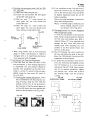
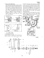
2. Claw PositionAnd FramingAdiustments:
a. lf the claw does not enter the center of the
film perforations,or if the framing adjustment
is insufficient, the claw position should be
adjusted. This adjustrnentcan be either horizontal or vertical. To adjust the fulcrum assy.
slightly laosen th€ two screws {C} shawn in
F r s -# 3 2 & . 3 3 .
{1} Checkingthe Framilg Adiustment:This is
best accomplishedwith tfie proiector running, showing a shap test film. With th€
framing control lever in the up pcsiticn,
the frame bar of the film should appearas
in {Fig. #}51 and in the down posirion the
frame bar shouldappearas in (Fig. #36).
Fis-#35
{2} lf thc conditions in step I are not corr€ct,
adiust the vertical or up and down posirion of the fulcrum assy.{Fig. #Z Afil
by slightly loosening scretvs {C} on the
fulcrum assembly.
Only a very small movementis requiredto
effect the framiilg position.
NOTE: lf framing rang€ as indicated cannot'be reachd, cheek for a worn
cam follower (32 af Fig. #31|
(gl QTT!11Sf"rttb" rr, !".*cr Atlglrmenl
lVith The Sprocket Holes:
To vie* thie claw position in the sprocket
holes, thread a strip of good filrn. Remove
the film shoe and brackat assy. With a
standard 50mm {2"} lens installedt,look
through the lens- Focus and rotate the
inching knob while observing rhe claw
position in the film sprocket holes. {Do
not turn on the lamp).
(a| Fig. #37 indiciatesthe csrrect position of
the elaw iust before the $tart of the pulldown. Fig.+38 indicatesthe positionafrer
completionof thc pull dawn.
(5) To adiust the claw position,movethe fulcrum zsty. harizontal and slightly vertisal
until the distancesa, b, c, d are equal as
indicatedin Fig. *37 & 38. Upon completion of thc position adjustment, tighten
the fulcrum assy- screws and re-check
the framing range with the projector
runn,ng.
Fis' #gt
Fw.#*
EEFOREPUIL DOWhI
AFTEBruLL D(NTN
rl
t t
ql
t
l
_l L_
e
PERFORA
Fig.#3e
cLAllt
t,o" r-*_l
ll-'-l I
_J L __.10F_
c
t l
I l-ll
-79 -
E- ReplacingThe_Claw
When replacing a worn or defective claw, it is
important to rnount the claw correctly before
sceuring the mounting $crews. lncorrect claw
rnountirqg may result in excessivefilm gate neise
or unsteadypicrure.
t. CcffegrclgrvPitch
The lnternatbnal dimensiort ol the f6rnm film
Frg. #3O
2- Adiustlng The Claw Pitch
a. Moving th€ fulcrum control assy: The fr.llcrum control assy lFig. #all harizantally
adjusts thc contact point betwe€n the cam
foflouer and the cam which i* turn effects
the claw pitch. Moving the fulcrurn control
assy. to the left decrcases the pitch and
moving it to the right increasesthe pitch.
Fs. #4r
CLAW LEVER
SFRING
TETTISIOFI
oso:o-os
Gf
c!
0
q
- l $ '
lt
q
c
+l
F
q
Gg
o
+l
q
n|
e
COTSTEOLA,SY
a
o
E
o
o
EI
CAM FOLLOTYER
b. The fulcrum control assy. should only be
rnoved slighrly. Tco much adiustment will
cause the claw to hit the sides of the film
perforationscausingfilm jitter.
c. Carrect claw angle is shown in Fig- #42-AUnder some cirsumitanc*s a bent claw lever
as shown in Fig- #42-B and 42-C may have to
be ccrrected by straighteningout lhe claw.
a. The lnternational dimensions of the l6mm
film are shown in Fig, #39. Claw pitch is set
at 7.64 - 7.67mm. A pitch lessthan 7.64mm
will causethe claw to engagethe film between
Fis' #42
'
perforations possibly causing film damageor
unsteadypictures.
b. A pitch morethan 7.67mm will causeexcessive
gate noise. Typical film perforation should
3. Claw LeverTension (SeeFig.*41)
have a pitch of 7.605 - 7.635mm, but older
The claw lever tension force should be from 1.2
films may have a smaller pitch due to shrinkto 1.25kg when the spring is stretched to the
agF.
maximum travel of the elaiy lever arm. lf the
c. The claw as shown in {Fig. #40} has a 5
is too weak, the cam follawer may float
tension
degreeangle at the top tooth, and should the
off rhe cam surface causing excessivegate noise
claw pitch becomelargerthan the pitch of the
and an unsteady picture. On the other hand,
perforations,this would help preventany film
if the spring is too strong the cam follower may
damage.
wezr ottlt prematurely Ei ealrtfta sligfit hesitation
Fi8'#48
. tT S*
of the claw lever when the projector is initially
ttarted. To obtain the correEt tension it may be
necessaryto replace the spring. A slight adjustmeni can be made by stretching the spring if
necessary-
=df :+ =d
-an-
F. ChangingShutter B!4des
mtst|ltc
Fb. #rr3
:
tt
:
t
t
t
t
t
t
l
t
I
t
r-------t
t
l
t
l
UPFERGHOST
I
$EI|il-CtRCLE
Fb. #45
n
tr tr
LO{IIERGHOST
Two, three and five bladed shutters can be mounted
on the shutter pulley. The mounting holes usedto
securethe bladesto the pulley allow a srnalladjustment for shutter blade timinp. Incorrect shutter
timing results in what is commonly called "ttavel
ghost". The adjustment is accomplishedusing the
NOTE:
SMPTE test film and adjusting the blade posirion
for minimum upper or lower imagemovementas
shown in {Fig. #43}. Since the adiusting scre$'s
are only accessiblewith the cam tank removed,
thil becomes avial and error adiu*tment. Ho*ever,
the skilled technicianscan ascornplishthis in one
or t\ro adjustmentsWhen mounting the 2 blade shutter, the missing
semi circle on ths hub must be positioned toward
one of the blader. The curved edge of the blade
faces away from the cam tank {See Fig. #44,
4sl.
Fh- #4{
PRIIIIEBLADE
HUB
-31-
3 BLADED SHUTTERS IIYILL AUTOIIIATICALLY LIFIE I,'PC-OREECTLY.
G. Still PictureClutch
fne stitl picture clutch consists of the shutter
pulley (50|, the shutterbladeand hub {a6} and rhe
still picture clutch lever {55) and uensionspring
(12). The ftiction betwee* the shutter bladehub!
coned $urface and the coned surface of the rhutter
pulley is maintained by the tension spring (12)
when the still picture clutch is in the up position,
driving the cam tank and fhe r€st sf the projector
mechanism.In the down position the still picture
lever releasesthe spring tension, slightly separating
the shutter blade hub and the shutter pulley. To
adiust the still position clearance,spacer{54} may
be added or deleted, as necessary.Lubricate the
bushing with a small amount of molybdenum
'the
disulfide grsase. In
still position th€ heat
filter {57} allows a single frame to be shown
without burning the film, however, the proiector
is not designed to sperate in this position for
extended periodsof time. Long still operationswill
caus€Frematurewear to the shutter pulley bushing
and cam tank shaftFq'.#*
51
52
$l
-3?-
(NOT[: NT proiectorsafter SIN ?6135and NST
after S/N 10674 are supplied\'/irh 36V
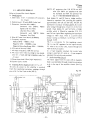
Referto the amplifiercircuit diagram:
AC standard and 40V AC oprional"Sce
A. lp*91lggtiqql
Sec.4-4 TRANSFORMERMODULF,)
1. Solidstate;3 lC's7 rransistors
{g transisrorsDual diodes 51 and 52 form a bridge rectifier,
for -3 type)
[iltered by capacitorC44, providingthe amplifier
2. Ourput power: 20 watts RMS I ahm load
approximately56V DC {or 50V DC). The 8V AC
3. Distortion;Lessthan 4o/o
at 40OHz
transformersecondarywindingsuppliesAC exciter
with
SMpTe
400H2
{measured
lamp voltagethrough pins 14 and #5 of the 9 pin
SignalLevelTesr Fitm|
socket. Dual diodes 53 and 54 form a bridge
Lessthan 19lo
at I KHz
rectifier which is filtercd by capacitorC14. Cl5
wirh
SMPTE Mutti. and Cl6 are ripple filters regulatingthe baseinput
{measured
FrequencyTest Film)
voltage to TR-l 's base. R-32 is a current *nse
4. Wow & Flutrer: Lessthan 0.2%WRMS.
resistorservingas feedback to the baseof TR-2
5. Frequencyresponse:
through R-29.
Optical 50Hz - 7000H2t 4db
TR-2 is a protector for this regr.llatingcircuit.
Magnetic5CIHz* l0000Hz t 4db
TR-l is the DC regulator for the approximately
MagneticRecordingRange50Hz l0000Hr
3.5 volts to thc cxcitcr lamp, routed throughpins
6. S/N ratio of the amp: 60db
*8-9 of the 9 pin socket,
7. Mic input impedance;
6O0ohm and up.
ln -2 rype magnetic playtrack the excitrr lamp
8. Mic input level:1Ornvmax (highor low imped- voltageis switchedoff, while in -3 type magnetic
anse for -2 type and high irnpedance
playbackthisswitchis not provided.
only for
-3 rype.)
c. |qdi" Ampllktltrsgl
9. Phonoinput level:50rnv{highimpedancc}
The input signal from the solar cell or magnetic
l 0 S p e a k eJr a c k s 8: o h m
headis accomplishedthrough rcspccriveminiature
iacks in the top of the amplificr chassis.(SeeFig.
B. AmplifierPowerSupplyCircuit.{r*r-nj6,47)
40 volts AC power ro thc arnplifier is supplied *4t)
4 - 2 : A M P L I F I E RM O D U L E
from the transformersecondarywindingsthrough
pins#l & 2 sf the 9 pin socket(MT-91.
Fig. s47
SP.J for Front
Cover Speaker
FUSI 2A
-- d\9
FiJSE2A
C4.?p0o{F
---f
I
'\'
.}1 1
L
fit
dl
F4
*
.s
!
q)
-!4
!0
ru
l . B
oul
k
F:
$
$T
$
$
e^t
t6 (J
{
$
Y.t
EN
*33-
{'
. ?
R46 presentsa 10K impedanceload to the solar
cell in optical playback. C42, R5O, R54 and C48
for the input equalizationnetwork. The signalis
coupled to lCl (AN360) through eapacitor CL
Feedbackto lCl is accomplishedthrough a selecrable network consistingof C18, R?, R3, R5 and
C21. Position1 and 3 of opticallmagneticselectcr
switch providesa linear responseof lCl, position
2 switchesin the magnericplaybackequalization
required-Basscontrol VR-l, R8, C25, CZ4 end R9
form a low frequency boost and attenuation
equalization network- Treble control VR-2 and
C22, C23 provide for high frequency boost and
attcnuation. Thc signal frorn the tone controls is
fed through C6 tc pin 2 at lC2. Thcoutputof lC2
is coupledthnrugh C7 ta volume control VR-3,lo
pin I of lC3 through capacitorC28. Feedbackfor
lC2 isaccomplished
throughthe network consisting
o f C 8 , R ' 1 2 ,R 1 0 , R l 1 , C 2 7 , a n d R l 6 . F r o m l C 3
the signal is fcd to TR3, TR4 and TR5. TR6 and
TR? act as complimentaryfinal output driversto
an 8 ohm speakerthrough capacitorC13.
5incethis is a singleendedcommongroundoutput,
Output Transformer Less{so called O.T.L.
should
be
taken to avnid a ground
circuit), care
loop condition which may result in amplifier
damage,when conncctingthe speakerground to an
externalearthor electricalground.
D. Masnetic Record[49_d4r(NST-3 & NI!]
NST-3 & NT-3 modelswith magneticrecord use a
special amplifier module which include the bias
and eraseoscillator circuits. This circuit consists
of Tl and sscillatortransistorsTR8 and TR9.
ln magnetic recard, the Mag/Rec selector switch
set to the No. 3 position.Audio from the speaker
jack @ is rauted through the capaciror resistor
network C-38 and R41 to the magnetic record
head, At the samc timc bias and crasccurrcnt is
suppliedfrom the biasosillator to the cornbination
magneticplayback/rccordand eraseheadE. Amplifier Circuit Diagrams
'1."N"
seriesAmplifier Diagram{See the end of
this manual] f, 73'+-t P tY
2. "N" seriesAmp. P.C.BoardBlock Diagram{See
the end of this manua|\ P,7l
3. "N" seriesAmp- Frequency Response(Seenext
page)
Fig- #48
llrAc sH.
Rli4?t
Rtz rA
to efaset
-34-
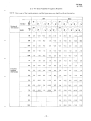
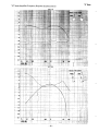
Response
E-3:"N" Series
AmplifierFrequency
NOTE:Thisis oneof the typicalpattcrns,
afidrhefiguremayvaryslightlywith eachprajectorOPT
, . * * d ! ,i_)'.. v
."jF--,
ro'rfft}n or
Tone Cantrol
BASS
i
MAG
'--\
1 ,\,3
\t
i
't)I, "J O
Y
f',
50
3.5
- 12.0
100
3.5
-7-5
200
0.s
so
o.o
500
t-5
2.0
0-5
I
0.5 i
1K
3.0
3.0
2.0
r.0
2R
3.0
l).5
3.5
:1
2.5
-4.5
4.5
-oo
rt.- - Vj
/'F\
r
"tt'i
l ,-\
V)
t)
| ,.'- -, /^\
o
\- ),t'{L.,i
ft,
\, ri \_t V-I
't0.0
8-5 - 1 1 . 0
1.5
-15.5
6.0
5.0 - 1 4 . 5
8.0
7 . 4 I -7.0
1.5
-9.0
6.5
5.5
-8.0
-3.0
4_0
3.O
_30
*0.5
-4.5
3.0
2.0
*4.0
-t.o
1.5
-t.O
-o.5
-1.5
lO
1.fi
-t.o
2.o
0.5
1-0
-0.5
l_ o,
4.0
3_9
1.5
-2.O
5.O
z-o
-6.O
s.5
6.5 -r.o
I
5:s
.
.
I
.
l
_1.0
1.0
0.0
-0.5
-t.o
3-O
-2.5
2.0
-3.5
5.5
-5.0
7.0
89
2_O
-5_5
T
-7.5
8.5
6.5
3.O
-i.r_
9.O
-8-5
10-5
3.0
-7.5
't0.5
-s.5
1?.0
.99 12!_
-10.0
13.0
3.0
I
Frequency
Rerponse
{4O0Hz Odbl
ilK
5K
_3.o i
__?:t .-1o-0.
I
J-12.o
I
6K
-3.0 ,-1i.5: 3.0
---r-- l-,a.0
t
-5.O l-rg.o : 1.0 .-?o.a
t
1
l;
_.5
9K
10K
i
i
-35-
2.5
4.4
4.O
-9,5
1?.0 - 1 t _ 5
3.0
-1 1.5
12.0 -14.0
5.O
13.5
13.0
i
t.5
-15.0
10.0 - 1 7 . 0
11.0
oPT (21
i
i !'
l
' ' - il - - - : !:-. ,
'--.1---+---i--
, i ': , i , ,
-.=j__*J_r
!
l
:
i
l
,:
MAG{1}
l
i
l
l
:
:
I
MAG {2}
MAG {3}
-38-
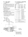
B- Mator Circuit Siagram
4-3: MOTffi FIODULE
A- Speclflcation
AC Induction type
1'2OHP
gR(}{s[|
THENTilAL
100- 120V,and220 -24QV
Foxerconsurnption:
144-- 168W{120V,1.2A}or
(?tr, 24SVg.7Al
Starting Torque: l,6kg
RatedTorque: 0.8kg
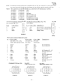
C. 6 pin ft{ctcr Connector {Fernafe}(Fig. #50}
t!!-f
tUire f*lor
Connected To:
1.
2.
3.
4.
Brown
$thit€
MicroSwitch#1
MicraS\ryit{h#2
5-
6.
Nlc
Elue
Grey
Red
fHicnrSwitch#3
MicroSwitch#3
AC Terminal#4 - #3
{Semko:TerminalSr)
Fis. {lgc
-3,9*
Fig.#e
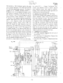
D. Silent Film Operylron And 5O* 6OHzConveL:
sion
1. Silent Film Operatic_n
a. Disconnectpower cord.
b. Open rear cavel. Turn inching knob, at the
sarnetime guiding the belt first to the smaller
motor pulley then to the largershutter pulley.
c. Changeback to sound speedby reversingthe
absve procedure.
NOTE: 5O/6OHz models do not have silent
swf'd*
2. 50 60Hz Conversion
The standard "N" reries proiector is available
either as 50Hz sound and silent or 60Hz ssund
and silent operations. Conversion from 5O to
6OHz or 60 to 50Hz can be accomplishedby
changingthe motor pulley only.
ry
I
To allow the proiector to be operated at either
50 or 60Hz sound only, it is necessarytc change
the motor pulley and the cam tank pulley
(Shutter Pulley)- lt is now pcssibleto change
frequency by simply shifting the motor drive
belt.
The chart below indicateseach speedcsmbinatis*:
NOTE: For Dual-Voltagemodels,such as 11Ol
220V, ar 120/240V 50/60H2,the combination ir;
1101220V 12s{240v
soFoHz
50re0t+.
Pulleyr
Shutter
f tTll gOt
f r Z-rrg0r
Motor Pulley :
314-12991
3'14-12981
Chilge CombinationShert
SOHzSound & Silent
{24fps & tSfps)
.
1
I
i
'---'---
SO/6OH.Sound/Sotrnd
(24fps& 24fps}
i
'
OOHrSound & Silcnr
{24fp & tSrp}
ShutterPulley
312-t1801
3r2-r1S01
312-11801
Motor Pullqy
312-129?r
3r4-r2971
312-t2g1t
50Hz 24fps s
Sound {24fpr} speed
Sound (Z4fpslspeed
W m
I]
tf.llrrt
dt llErDI
"u
LIITT
Silent llSfpslspeed
\l
Sound 60Hr 24fps speed
Sif"nt {lSfps}
Silent
rp**d
tfSfprt speed
lrl
lll I|
ilth
tft tr
llh|'
t _
il{tPtr
tt-'ll
:40 -
i
!
tl-4: TRANSFORfTI€RMODULE
A. Transforqqlllgg!! !bgl4!!
(EarlierProduction)
Applicableon;
NT :SlN 10001-2613s
NST: SlN 100OI- 10673
EXGITEF LAfiP
{Later Production}
Applicableon;
NT : $lN 26136andup
NST :5/N 10674and up
Fig.*r5t
lsPEc
l{XtV}
---^ --
Fis' #52
ls?€c
2tXw)
'zq$t
FPEC
(S|PEC
tmvl
2{mtl
-1-----?{trl'
E
P
w-iiw--
E
E"t
E
II
..".c,--ro6;---zzsv
F
B
g-utrE€-_b_
>l
IJ
___w
HALT}GEItI
LAiIP
Hl-l-ost
B. ConnectorWiring Code
{Earlier Production}
9 Pin Nylon Connectol {Male) (FrS.,r{5.!}
Applicableon;
NT : S/N 1O001-26135
NST : S/N 10001 - W677
Pin #
Color o[ Wire
Frl6qT-zov,zzov,
240V*ypes)
Brown
Yellow
Nlc
Nic
White
Red
Black
Black
Red
{!-aterfroduction}
(Male)(Fig.#5a)
9 PinNylonConnecror
Applicable on;
NT : SIN26136andup
NST: SlN 10674and up
Color of Wire
iforTloV type only)
Brown
Grey
N/C
NIC
White
Red
Black
Blask
Red
Pin #
IETmq-
Color of Wire
{fw 1t0V
type onty)
&lorof Wire
{for tfOV
Brown
Yellow
N/C
Orange
White
Red
Black
Black
Brown
Grey
N/C
Orange
White
R€d
Black
Black
Brown
Yellow
Grey
Orange
White
Red
Black
Black
Color of Wire
120V,??0V,
240Vtypcs)
12.
3.
4.
5.
s.
7.
8.
TMALE'Fb- #53
uL a csA)
fMALEI Fb. #5r
-4t -
NOTE: Transforfiers of later producticrrarc suppliedwith the 35V tap connected.To changetc the 4OV
tap, extract pins #4, #6, and insert the orangewire into #6 hole and the red wire ta #4 hole.
NOTE: The transfcrmerwith AC36V & 40V taps ls identifiedby the following part numbers;
Transformer
120V
T44A2O1a
314-60301a
Transforrner 110V
Transformer
2201240V
314-60401a
Transformer 220V {FEMKO type}
314-60801a
314-60951a
Transformer
22OV {SEMKO type)
31tt-60981a Transformer 1f0/220V {Dual Voltage}
31460991a
Transformer 12OI24AV(Dual Voltage)
3 Pin Nylon cglgglgflF€n'ld
(for all typesJ(Fig. #55)
Fig.#55 3 pin Nyton Cannector{Male}{Fig. +56)
{for all types)
Pin #
Color of Wire
Pin #
1.
0range
Blue
White
1.
Red
2.
Blue
White
2.
3.
J.
Fis.#56
C-olorof Wire Connectionto'.
Micro Switch #5 (Lamp HiSh)
Micro Switch #4 tlamP Low)
HalogenLamp
tFEmALEI
IMALE}
9_Pin Nylon Connector {Female}{
Pin# C-olorqf \V.ire
{for 100V,110V,120V,
?20V,?40V standardtypes)
Color _o_l\iVjre Color of Wire.
{for 120V UL, {fer ?20V
SCAN type)
CSAtype)
Connectionto:
l.
2.
3.
Erown
Black
NiC
Brown
NIC
AC Terminal #1
AC Tcrminal#2
4'
N/c
5.
6.
White
Orange
N/C
White
Orange
f'llC
Blask
N/C
N/C
White
Orange
Nlc
7.
pBlue
t"Blue
lBlue
-Blue
;Blue
'Bluc
L
pBlue
LBlue
p Blue
L Blue
;Blue
L
Blue
Orange
9.
Orange
Orange
AC Terminal#4 - #3
MT 9 Pin Socket#1
(or #2)
MT 9 Pin Socket +r4
Pilot Lamp
MT 9 Pin Socket #5
Filot Lamp
MT 9 Pin Socket#2
{or #1}
{STANDARDTYFE}Fq. #57-A
Fts. #57-B
hzov UL& csA TYPET
Fig. #57-C
{zANVSBN & SEMKO TYPE}
IFETTJIALE}
{FEMALEI
{FEMALEI
_42_
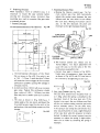
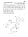
4-5: LENSAND GATEMODULE
A. Film GateAssembly
"
l[
-*
6d
79 _.
{
Ul^
15
$
29-
or dirt. The apertureplate {26) is mcunted to the
gate plate by two nuts, allowing it to slidc up and
down with the framing lever.The outer guide rail
Fic- #EB
{38} is fixed to the gatc plate by twc serews.The
inner guide rail {34} is movableand is mounted by
twn shculd€r scrcws and is adjustedby the side
pressurespring{36).
1. AdiustmentOf The lnner_GuideRail:
The tensian af the inner guide rail is determined
by thc side pressurespring {35} about 60 - 70
grams- Excessivetension wifl cause early film
wcar, while insufficient tension causes an
unsteady picture. The tension can be increased
ar decreasedby slightly bending the spring. A
\l
weak or incorrectly formed spring should be
replaced.
2. AdiustingThc Outcr Guidl n_qt1Po14io1:
Unlessthe gate plate has been removedor the
outcr raiI has been replaced, no adjustment
should be required.Ta adiust,thread a SMPTE
registrationtest film and align the cent€r of the
framc with the center of the apertur€ by adjusting the position of the outer rail- lt may also
Fis-#sg
be necessaryto rc-position the claw {See See.
ilrL,,
4-r-D)
B. Fifm ShoeAnd LensHolder Assembly
Fh. #60
APERTUg€
FL,ATE
I
hr
IH]{ER€UIDE
FAlL
OUTERGUID€
AAIL
3
!8IT'E PRESI',RE
;€PftIHE
FRAilING
LFYES
6ATEPLATE
The film gate assembly consists of the aperture
plate (26), framing lever(30), inncr (34) and outer
{38} guide rails and the film gateplate {27). The
film gateassemblymaintainsclosecontact with the
film and must be kcpt free from accurnulateddust
f
T
__l
4
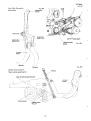
1. Fjfm Shqs{Fig-#60}
The film shoeassenrbly{?) consistsof the filrn
droe {5), the threadingreleaseplate {6} and the
shoe lock {3). The film shoeassemblyis easily
removablewith the shoe lock for clcaningor
replacement.lt is important that the shoe be
kept clean and free to seat squarely againstthe
aperture plate. The threading rcleasc platc
engageswith the self-threadingmechanism to
releasethe filrn shoeduring threading.
_43_
Fb. *er
b- Film ShoePosition
WEenlE gat€ is closed the film shoe should
line up along the edge of the outer guide rail
and seat flat against the aprrture plate. To
adjust the position of the film shoe, loosen
the retainingplate scrsws[11], closethe film
gate and insert one film thickness between
the outer rail and the film shoe.{Fig. #6?}
Reposition the retaining plate to obtain
moderate tensios on the film and securethe
rctaining plate screws (11|. Open and close
the gate to be sure the film shoe seatscompfetefy.
&
tl
FILM
Fic.see
1S
2. Lens_Holder
{Fig. #61}
The lens holderconsistsof the lensholder barrel
{9), the focus knob (16) and the lens friction
drive pinion, the upperand lower shoepins {12}
and springr{14} and {15}.
3. Adiustments
". l-.tln Shoe Pressure
The pressureof the film shoeagainstthe film
is maintainedby the tension springs{14 & 15}
located behind the shoe pins {12}. Excessive
film shoe tension will causeunnecessaryfilm
wear, inzufficient tension can cause an unst€ady picture, excessivefilm gate noise and
unevenor erratic focus. To test the film shoe
pressur€retract the cam claw, insert a strip of
film in the gate and slos€ the gate. Attach a
gfam scal; to the end ofthe fitm at the top- A
gentle steady pull should produceabout 90 to
ll0 grarm of pull, indicating the corrcct film
shoe pressure.To adjust the presrure,stretch,
shortenor replacethe shoesprings,
NOIE: The upper spring is shorter than the
lower spring. The extra tensien af the lower
spring is designedto overcome the film movement causedby the claw action at the lower end
of the film shoe- lt is important the shoe pins
move freely in the lens holder. lf noq clean
away any dirt or grease restricting its free
movement.Do not lubricate.
-44-
c. UnevenFscu;
Uneven focus occurs wheneverthe imageon
the film is not flat and perpendicular to the
optical path. To adiust the axis of the lensto
the aperture plate, set the proiector to exact
right anglesto the screen. Without a film in
the gate, project an imageof light on a screen
at least3'or lm wide.Focusthgedgesofthe
image. lf both sides ar-enot focused equally,
adiust the lens holder index screv,,and lock
nut {19 A 2A} to achieve optimum equal
focus.
NOTE: Fast lensessuch as the standardfi 1.2
50mm {2"} require more precise
adjustmentsthan slower lenses.
d, Lens Holder Hinge Adiustment
The lensholder providesfor autamatic closing
of the No. 1 film shoe when manually thread-
ing the projectorand restrictsthe openingof
the film shoeduring the self-threadoperation.
Too tight a clearancednes not aflow for easy
film threadingor removal,and may possibly
puncture the film between the perforations
during self-thread.The clearancebetweenthe
No- 1 film shoe and the lens holder shculd
be no lessthanthreefilm thickness.(Fig.+63)
To adjust, open the larnp house door and
loosen two set screwsbehind the gate plate
(29 at Fig. #58, and Fig, #61l; and slightly
turning the upper and lower pivot screws{?8
of Fig- #58, and Fig. #63) adjust the lcns
holder's position to obtain the correct clearance.The pivot screwsshould be snugagainlt
the lcnsholder.
Fis. #S3
}\
$ETSCREW
&,_
SET SCREW
&_-
LOWER PIVOT SCREW
1{
'!:
&
F}
I
in the spindlc assymbly {14} must be well
lubricated to provide a smooth, even take-up^
Excessivetake-up tension is causedby insufficient or impropcr luhricationof the cork liner.
Weak or no take-up may be causedby r worn
cork liner or cily belt. Referto lubricationchart
for proper lubrication.
5-l: TAKE-UPARM ASSEMBLY
A. Description(Fig. #64 & 65|
The drive to the take-uparm is obtainedthrough
the take-up clutch mechanism{ltems 1 1, 12 and
13). ln forwardand rewind the clutch cam (12) is
engaged,driving the belt and take-up pulley (18)
in a clockwise direction for normal fitm take-up.
In reversethe clutch cam (12) is disengaged,
removing all drive to the take-uppulley {18}. The
arnrlunt of torque required to take-up a film is
proportioned to the weight and diameter of the
reel. As the weight of the film pack incrcascsthe
friction betweenthe spindleassembly{14} and the
take-up pulley (18) increases
to provide the necessary torquc to take-up reelsup to 2000ft or 600m.
B. Adiusrments
1- The take-uptorque
The take-up torque is automaticallycontrolled
by the weight and size of the film pack, how*
ever, for this to function properly it is essential
that the take-up pulley (18) be well lubricated
and free running on the bushing-The cork liner
t8
I
--s
Fig- #64
ARMBELT
9EARINC
EOVER
SFINOLE PIN
C1OBKLINEB
Fig. #6s
2
t
10
I
I
I
I
&
Hr\Y/
-47 -
2. Take-UpClutch Mechanism:
The take-up clutch rnechanismrequiresno lubrication. The clutch cam {12), clutch cover {13},
and drivegear(11) shouldbe kept cleanand free
from dirt. A small amount of siliconeoil on the
drive pulley shaft is sufficient {see lubrication
chart). When re-assembling
the clutch mechanism, it is important that the clutch cam be
pcsitio4ed correctly. A s,pace of 0.2mm is
required between the drive gear and clutch
cover.{Fig. #56 & 67)
to the film. The amountof backrensioniscontrolled
by the cork disc {17} spring {20} and the adjustment of the knurled nut {22}. In reversethe motor
reversesdirection engagingthe reversedrive clutch
(18) and the reversebelt drivesreversepulley {19}
which is cfuteh coupled via the cork disc {'l7} to
drive the pulley {8) and spindle (23) providing
r€v€rsefilm take-up.
ln rewind the drive to the supply arrn is accomplished through upper and lower rewind gears
which are engagedwhen the rewind leyer is in the
rewind position. {Fig. #69 & 70}
Fis.#GB
T€ltlSlON SPRIIIG
IIUT
R€VEFSE
BELT
T.FPEF
GEAE
LOYTER
GE*R
CLUTCH GOVFR
PULL€Y
CLUTCH CAf,'I
DFIVE CEAF
5-2: SUPPLYARM
*. _nf:tp{gl: {Fig.#68}
During forward the supply arm only servesas a
dreg to providea srnallarnountcf back tension
Fb. *te
-48*
B. Adiustments:
The supply spindl€ should be lubricated with
petroleumoil {seelubricatisn chart}. The belt must
be clean and free from oil or dirt. Oily belt may
result in poor rewind. The knurled nut (221adjusts
the back tension ta the supply reel, too little back
tension will result in unevenor jerky film feed and
weak reversetake-uptension-Adiusting the knurled
nut effects both tfie rlverse take-up and the supply
tension.Correct adjustment will be a compromise.
i:Pt|lilG
Fig. #7!l
REYEBI'E
RUBAER
BOLLER
$guilDDEtril
SHAFY
SET COLLAF
Driving the flywheel is necessaryto maintain the
fower loop when operating the prcjector fn reverse.
5-3: REVERSEPROIECTION
In normal forward projection the main drive belt
A. Description
carries the reverse rubber roller and bracket
Fig. #71
assembly {15} away from the set cal}ar where it
can rotate freely. The rubber roller must not be
in contact with the set collar in the forward mode(SeeSec.5-7-A)
B. Adjustments:
The reversetake-up clutch requiresno lubrication
Exceptthe bushing of the clutch cover pulley {18}.
(See lubrication chart). ltfhen re-assemblingthe
reversetake-up clutch mechanism,it is important
that the cluich cam {19} be positionedcorrectly.
A space of approxirnately 0-2mm is required
between the drive gearassembly{8} and the pulley
{18}- This is determined by the porition of the set
ln reversethe motor rotates in a counter-clockwise collar {20}.
Fis.#74
direction engagingthe reyersetake-up clutch cam
I
r.--{19} which in turn drives the clutch cover pulley
(18), driving the reversebelt. At thesametime the
main drive belt drivesthe reverserubberroller (15
of Fig. *i72 & Fig.73l againstthe set collar behind
the flywheel, thereby driving the set collar or the
sound drum in the counter clockwisedirectionFis.#??
The reverserubber roller requires no adjustments
ar long as th€ main drive belt is in contact
with the rotlerk drive gear. The spring lzal is
required to maintain enough pressureto assurethe
gearscontact with the main drive belt. lt may be
n€cessaryto stretch this spring lo assurethat the
roller has clear*d the set collar in the normal
forward position and that it drivesthe sound drum
during reverse. This action can be observed by
operating the mechanisrnmanually via the inching
knob and with the flywheel removed.The rubber
roller should be clean and free from any greaseor
oil. A dry or glazedroller should be replaced.
11
12
l4
10
-49-
5-4: LOWER LOOP SETTER SYSTEM
A. Descriptign
Torn or damagedsprccket holes in a film will
cause the lawer loop to be shortened-lilhen
this occurs, the fl[m pull dow* wi]l be out of
sequencewith the shutter causing e iitter or
iumping picture. litlhentltis occurr the automatic
loop setter will resct the lower loop again
bringing the film under conrrcl of the pull
down rnechanisrn.
Fis.45
LOWER LOOF SETTER ROLLER
'?:3{l O'GLOCK" P0SITiOFI
gear {11) parallelto the main drive belt with approximately 0.5 to 1mm of clearance.The belt
must ride flat with respsct to rhe gear. lf nor, the
tension gear and arm assembly is not aligned
correctly. To correct thir condition it may be
necessaryto reform the tensiongeararm. With the
belt and gear parallel the loop setter roller is
adiustedto the 7:30 positionby looseningthe arm
position screw (10). While holding the gear in
place,adjust t}rearm position and securethe screw.
Operate the proiector withour fitm. lf the loop
setter rotatet ffiore than once with a smali arnount
of upward pres$ure,the spring (12) tension is too
loose. Remove the spring and slightly stretch or
replaceit- Re-adjust and test again.
C. Loop SetterTiming:
Corffiiffi[iliied
Fis'#zo
7' ---------r
for prawr operationof
the loop-setter. Set the projector to self-thread.
Turn on the proiector and insert a 2 - 3 meter
strip of good film. When threaded, releasethe
threading mechanism. Observe the loop setter
slrould only rotate once- Continucd rourion
indicatestoo small a lor*er loop. Too large a loop
will not reset the loop when missing or damaged
sprocket holes are present. The size of the fower
loop is determinedby the relationshipbetweenthe
claw and the #2 sprocket drive-
The automatic loop settcr consist! of the sctter
roller {6}, the hub assembly(li and the gear
and shaft assembly(11)- Whenthe lower loop
is shortened one complete frame or more, the
filrn applies pr€ssureon the setter roller (5)
which in turn causesthe cccentricgear{11} to
engage,rotating fhe s€tter roller one complete
revolution, pulling down on the film thus reestahlishingthe correct lower loop. Additianal
rotations may indicate severelydamagrd film
or incorrect loop scttcr adiustments.
B. Adiustments
In the normal operate position with good film the
loop setter roller should rcst at approximately
7:30 o'clocf {Fig. #75}, v;36 the flat side of the
-50-
e
@
#Z SPBOCKET
COVEB SCFEW
@
the sprocket teeth plate counter clockwise (Fi
#781. To decreasethe loop, ratate the sprock
teeth plate clockwiw (Fig.+79). Tightenthe cov
screw. Unthread the projector, re-thread ar
releasethe threadingmechanism.lt may requi
several repeat adiustments to achieve appro)
mately5mm of clearance
betweenthe loop and tl
laop setter roller {Fig. +77}. Correcrtiming tr
resultin one loop settercyclewhentwo successi
damagedsprocketholesor
a badsplicepassthrcu;
the gate. In somecasescontinuouscyclingof tl
loop setter maybe e*usedby very poor or damagr
film or too stronga take-uptension-Excessive
tak
up tensionrnay causethe film to skip overthe j
sprocket drive resultingin lower loop lass"{5'
Sec.5-l ).
T@SMALL A LOWERLOOP
TOOLARGEA L(MER LOOP
5-5: SELF-THREADINGMECHANISM
A. Description:
The self-threadingmechanismis activatedby pushing the #2 film guide f ?) into the threadposition,
Iocking the interfocking bracket {14} to the refease
bracket(8).
At the sametime the #1 film guide(1) is extended
from behind the castingto guide the film into rhe
film gate while forming the upper loop. The film
shoe is releasedby plate {8} and the claw is retracted out of the gate by plare {7}- Film guide #?
{12} lines up with guide #3 {?2) and the rubber
pinch roller (33) is releasedfrom the sound drum.
The loop setter is locked out by the safety arm
assemblywhich exerts a downward pressureagainst
the main drive belt preventingthe loop sstter gear
from activatingthe loop setter during the threading
operation. The lower porticns of the lamp houre
cover provide the guide.rnecessaryto complete the
threading. To thread, turn the function switch to
forward, set the #2 tilm guide to thread, insert the
film into the film channel. When the film exits at
the last roller, a light tug releasesthe threading
mechanism.The proiectar is now ready to operate,
the safety arm is relemed and the laap settcr ir
activated, the film shoe and claw lever is also
released.The tension around the $ound drum is
automatically controlfed hy the tensisn of the
rubberpinch roller-
Frs.#80
5
4
3
32
12
-52*
SELF.THREADFILM PAT}'
#I SFROCKET
#T FILilGUIDE
v_-"
LAST
ROLLER
AUTO.T*I(E{P
GUIDE
(hFT}
#2 SPFOCXET
#2 flLt$cutDE
*
**
TEfrfSlOll
& ROLLERS
sotrlrD DRUHi
SETTER ROLLER
MECHANISM
SELF-THREAD
(Main f nterlockingBracket)
#3 F}Li'
GT,'II}E
*3 FILf$ GUIDE
* 53:
Cam Cfaw Retractian
Mechanism
FILMSI.(IE
PTJSHPLATE
LOOPSETTER
GEAR
\
\'
v
\r
\
1
l
1
t
,
B
i
!
l
l
r
j
f
t l
OPEFATE
Rubber Pinch Roller &
Main Interlocking Eracket
ilJTI|E Ifl TERI-OICKI|'|€ ERACK€T
#Z F]LM
GUIOE
-54*
FrS.#84
8. Adiustrnents:
shoe wears,the clearancewill becsme too great,
t - #1 Sprocket Shoe Asseqp{y:
requiring replacement. When a replacement is
The #1 sprocket shoe is spring loaded to keep
nat available, the srnall protrusion which
the fifm in contact with the sprocket teeth,
dcterrnincs the clearance may be filed to the
driving the film into the gate.
correct clearance.
Fis.#88
For manualthread, it may be openedwhen the
lens holder is open. Ctreck the shoe clearance
using three layers sf film in the following manner:
First insert one Scm {2"} strip of film into the
25
film channel, advancethe mechanismusing the
CLEARAHCE
-23
inching knab- When the first strip is fed through
PROTRUSIOItt
the film shoe, insert another strip on the first,
continue to advance the inching knob. t4tith
two thicknes:es of film, the shoe should not
Too littlc or no clearancewill causefilm \ilearor
begi* to open. Next, insert a third strip and
damage-Care should be taken when removing
advance the inching knob. This time the shoe
the shoenot to losethe "V" spring{?3).
should slightly open with three layers of film
2. #1 Film Guide_:
betweenthe sprocketsand the shoeIn the self-threadposition, the #l film guide {1,
Frc.#€6
Fig. +80) is extended from the main casting,
guiding the film from the #'l sprocket and shae
into the fllm gate.After rhe threadingmechanism
is released,the guide recedesaway from the film
path.
Y
Fig. #09
4t Fl|-il
#T FILM SUIOE
T
l,{9TEr A simple test film may be madc by
cementing three short strips of film
together.
Fig'#sz
r
._6cm
_ ___+F_ 3fltt +
15cm -_--
ggrr __--__---____q
.r
Under normal circumstances,the shoe does nol
require any adiustments, however, as the film
-55-
COHTBOL
BAR
The film guide travels approximately 20mm
from operate to self-thread- This travel is not
srirical. There should be enough trayel for the
guide to retract away from the film in normal
operation,and in self-threadextend to the width
of the aperture plate- To adjust this travel,
loosen or tighten the scrcw and jam nut. tsec
Fig. #89).
NOTE: The position of the cam tank may
affect the position of the control bar
which activatesthe #1 film guide- lt is
important that the control bar aligns
with the #l film guide.
3. RetractionOf The Claw:
When the #2 film guide (12) is ser to self-thread,
plate {7} pushesthe claw away from the gate.
The claw must be completely r€tracted,however,
if it is pushed too far, the rear of the claw lever
will interfere wlth rhe $hurter blades. A loud
click, click soundwill be heard,
Fig.#Sl
mounted to the pivot shaft of the #2 film guide,
activatesthe interlocking brac{<etsub-assy.(14}
engagingthe releasebracket assy. {32) locking
the mechanismin self-threadposition. To adiust,
it may be necessaryto reform the latrhing pin
on the releasebracket if the mechanismwill not
set to self-thread.
Frs,#91
r-eG
I r-30
l l
d,sP*-
n
'-f?
_i
A smalf arnount of silicone greire on latching
pin is required for smooth operation of the
latching and releasernechanism.lt is important
that tfre #2 and #3 film guide line up with a
minimurn of clearance.Too much cleara*cewill
allow the film to ga underthe #3 guide.
a
H
_6
J\
2E-
I
t
SHUTTER
BLADE
-tz
LATCH}TTG
3t_
32
CLEARANCEMTX'TBE
uAfitrTAilrt€o
rr
a
t4
h
,4
4
4
v'1
Fig. *S?
n
v
A
4
A
-1
FILM GUIDE
l
CAM CLAW
crfr cLAs
PUSFI FLATE_.
\
\
t
<l-'
\_----
-"'
#3 FILIIIGUIDE
t
t
t
l
i
t
5. SoundDrum RuhberPinch Roller:
{Fig. #92,93}
To adfust this clearanceritis necesary to slightly
re-form the plate (7! decreasingor increasing
the claw:s retraction. In instances where the
shutter blade has been bent, it may be necessary
to re-form the shutrer blade.
4. #2 Film Guide:
The #2 film gulde acti as the self-threading
mechanismsetting lever- At the same time it
forms the path for the lower loop- When the
#2 film guide {I2) is set, rhe cam bracket (13),
-56-
lltf{|lrftr}l
CLEARAHC€
Fig. #*l
RI.I8BERPINCHROLLER
GUTDEROLLER
The sound drum rubber pinch roller is mounted 6. TensionGuideAnd RollerAssembly
on the #4 film guide (or pinch roller bracket
Fis' #gE
3'12.',79911*hich direccs rhe film up and oyer
the sound drum in the self-thread operation.
This is accomplishedby the interlocking bracket
312-17091 wfrich depressespin 312-17361,
TEITISION.
raising the rubber pinch roller away from the
GUIDE
sound drum. When the self-threadmechanisrnis & ROLLEFS
released,the rubber pinch roller rests firmly
againstthe sound drum.
The tensian guide and roiler assemblyprovides
It is important that the rubber pinch roller be
the dampening required between the #2 sprocket,
kept cleanand that it rotatesfreely on the shaft.
drive and the sound drum. Whenthe guiderides
Removethe roller to clean and lubricate.
midway between its limits, wow and flutter is
lf the roller does not turn freely, it may restrict
minimized. During the self-threadoperation, the
the film from advancingover the sound drum
tension guide {4I} provides a path for the fitm
during self-threading.A dirty or resrrictedroller
totravelfromthesound drum to the#Z sprocket
may also contribute to excess wow & ffutter.
driveTo adjust the tensionsof the pinch roller, push
Fis.#96
the #2 film guide to self-threadposition.
['-*
a. lnsert twc layers of 16mm film between the
shouldersof the rubber pinch rollcr and lamp
housecasting.
b- Locate pin 3f2-17361 so that it touches the
bottom edgeof the interlocking brackrt.
c. While pressingthe rubber pinch roller toward
the casting twith filrn between the roller
shouldersand casting),tighten the screwthat
1l
holds the pin bracket to the rsbber roller
shaftFrg#*l
sr-t7srt
sFRllre
l r -
t ^J-.. I
HAIil
TilTERLSCKING
g,a-r7Esl
BEASKCT
.__
:ii;o
fd'i'?tit
K',+h
S0lrlrD DRuffl
sT.lt-ir
ABM
sT-r7tgl
GUIDE ROLLER
312-t?gSt
SRACKgT
-5 7 -
ttz-t #?
Flil
must be clean and
l42l
rotate freely on the shafts. The tension guide
assembly(41) must pivot freely without bindingA rhythmic movement of the tension guide
roller assembly indicates that a roiler or the
sound drum is binding or out of round. An outof-round or bent #2 sprocket drive will also
cause exc€ssivetension guidc movement. All
cf the above symptoms will result in abnormal
wow and flutter. The tension of the guide and
roller assemblyis determined by spring {49} and
can be adjustedby replacingthe spring or slightly
stretching ar shortenlng the rpring to achieve
rninimum wow and flutter. All nylon rollers
shauld be cleaned wirh alcohol and lubricated
sparinglywith silisoneoil.
otherwise it must be replaccd. For correct
timing adjustment of the #2 sprocket drivc
assembly, refer to the loop setter section.
{Sec.54}
The #2 sprocket shoe keepsthe filnr in sontact
with the sprocket teeth. The shoeshould always
remain closed on all self-threading projectorsThe shoe tension is maintained by the "V"
spring (55). lt is important to note that the #?
sprocket shoe spring is stronger than the $1
sprocket shoe spring, The proper clearance
between the shoe {53} and the sprocket drum
{a6} is very important. To test this clearance,
take short piece of film and feed it into the #2
sprocket using the inching knob to advancetJre
projectorsmechanism.Add anotherstripof film
ofl top of the first and advancethe projector.
With a double thisknesssf film the film shoe
should not begin [o open. Add a third layer cf
film and advance the projector. This time the
film shoe should begin to open, indicatingthat
thc shoe clearanceis correct.
NOTE; A simple test film may be made by
cementing three short strips of film
together. (SeeSec.5-5-B-1,Nate)
7. #2 SprocketAnd ShoeAssemblyi
Fis.#97
52
47
Fig- *"9g
,18
*
3cm .f
.----8cm-d
-- 43
F -
{
lScm-*
is dctcrmined by
The proper film shoe cleara.nce
a small protrusion moldcd on the shoe which
indexesthe shoeagainstthe bushinghub {50}.
59
58
54
Fis. SB
Y
L55
The drive consists of the sprocket cover (48),
the sprocketteeth plate (47), the sprocketdrum
and shaft {45}, the hub and bushing assembly
(50), and the drive gear (52). There must be no
end play of the sprocket drum shaft in the
bushing. Small fibcr washers {G4-070120,
G8-0701?0| are insta|led to achievethis condition. The sprocket plate (47) must be in good
condition, with no defective sprocket teeth,
-58-
FILMSHOE
PROTRTJSIOH
53
As the shoe wearsit may be necessaryto replace
it to ohtain the correct clearance-In someeases
the shoe clearanccmay bc rcduced tly filing thq
protrusionToo close a clearancewill reufl i61
!!UTION:
poor threading or possible nlql
damage.
T'
5{: REtflND MECHANISM
(Fig.#100, 101)
A- Description
The rewind is accamplishedby threading the film
from the take-up reel to tlre supply reel, and
engagingthe rewind gearsby pressingdown on the
rewind lever, then switching the projector to the
Rewinding
w-)E
4t{'d
B- Adjustments
The am6ffi of gear lash is determined by the cap
screw {38)" Thc tension of the rewind lever is controlled by the spring {37}. The rewind gears {45}
and {49} must mesh comp'€rely wirh only a slight
amount of lash to avoid unnecessarywear, lt is
important that afl the gearsroff freely with a slight
Fis.+1O0 amount of silicone oil on the shaft. The rewind
bracket assemblyshould also operate freely on its
pivot shaft {33}.
*it
Fig. #1&l
'.1,.{i
ti
d(i
*Eu$tirD TEn$O$
SPFING
EeeE}|?nrc
Whenthe rewind lever{24} is engaged,the eccentric
*raft {25} releasesthe pressureto the cap s€rew
(38) causing the rewind gears {45} and {ag} to
rnesh,thus positively driving the supply arm.
-
- 23
Fis. #1O1
&r-r,
e r \
CAP SCFETV
L(NTER
GEAN
--38
SNAEXET
5-7: SOUNDDRUM AND FLYWHEEL
A. qg$_tE!ro!.
The sound drum and flywheet assembly'smain
function is to stabilizethe film, allowingthe sound
optics cr magnetic head to read the sound tracks
with a minimum of speed variations. The ssund
drum, shaft, bearing and flywheel are precision
machined and balanced to maintain a cansistcnt
linear film speed,Care should be used when disassemblingor re-assembling
thescprecisionparts.
h
-5S-
The sound drum shaft {5} is seatedin two precision
ball bearings {3} which are sealed and factory
lubricated. The ball bearingsare lightly presrfitted
into the sound hub casting{2}. The shaft is secured
in place by a set collar {6}. With rhe fiber washer
in placa,with no end play in the sounddrum shaft,
it msst rotate freely and not bind- Any binding or
imperfections in the ball bearing will result in
excsssivewow & flutter. In the forward direction,
the sound drum shaft {5} is driven by the tension
of the film. The flywheel is free ro slip on the
sound drum shaft during the initial start up of the
proiector to prevent any possiblefilm damage.In
the reversedirect'ron, the set collar {6} ls driven by
the reverserubber roller, allowing the film to be
transported smoothly acrossthe sound drum in the
r€yers€direcrion.{Fig. #103, 104, 10S}
B. Adjustffents
The drive torque to the flywheel is determinedby
the tension of the plate spring {8}. The normal
torgue should be between 2B - 25 grams. To
chesk this, use a gram scale and attach a string to
L-JuI
Fis.#to4
*_ilI
,r""=**r"
Fis. #llE
R€VERSE
ERACEET
REVERSERUBBER
RT}LLER
#toe the flYwhe*l with
leig.
I r
SPRINGscALE
I l.'
FORHAN9
)rl adhesivetape. With
-a | no
*^ +ir^-^
filmirin +rrr
thepro-
20_zseniils-lil
jector,switch to
srwrrcH
tJ
iftl
.nsvenss*fr*Jll revers€
whilehold-
rAPE
AoHEsrvE
)-_
|
ing the gram scale
attached to the
string. To adjust
this torque, remoye
the plate spring
and bend to obtain
the corre€t tenEion.
A badly formed
spring should be
replaced-
{
i
#
| *o,"oJ,,r=
sELr
\
\
I (Fis.+106)
Fis,#tge
Ls
l_7
*60-
SOUND FOCUSING
Gl: OPTICAL
PROCEDURE
A. Description
Models NST-O,NT-0, NST-I and NT-l are optical
sound pfayback onfy. Models NST-2 & NT-? are
both optical and magneticplayback and NST-3 &
NT-3 are optical playback *ith magneticplayback
and record. The optical pick-up $ystem resemblesa
small preijector within a projector, consistingof a
light source,a lens,an image,and a screenor targgt.
Frs.#1O7
2. Set-up.Pracedure
a. Open the lamp house door and remove the
exciter lamp cover.
b. Removethe lamp housedoor with frame casting to obtain accessto the sound lens,
Fig. #l0g
-__-
EXCITER
ut|HP
_ LETGHOLDEB
EXGITERLAMP {BRK}
c. Insert the tool No. 3?0-02Tonts the larger
barrelof the ssund lensand tighten the set
screwon the tool.
Fb.#110
The light from the exciter lamp is focusedthrough
the sound track imagedonto the {target} :olar cell
where varied light intensity is converted into
minute electricalvoltagechangesthat are amplified
and cqnvert€d into acoustical variation or sound
which directly relate to the photographicvariation
reeordedon the film.
B. Sound Focus Al_igrl1ryI1-lrylg{g5!
1: Tsols and Eq*ipment Reguired
a. Screwdriverset {lso}
b. Sound lens adiustment tool (Tool No. 32002T. Fig. #.|08, Seenote below)
c. $MPTE sound focus test film 7000H2
d- SMPTE buzztrack test film
e. AC VTVM {audio range}and or
f. Oscillosccpe
g. I ohm 30 watt dummy load resistor
h. External speaker{frant cover}
Fas-#109
66
$OUND LENSA&IUSTMENT TOOL
320-{t2T
srlt r\lDLENS
TOOL
AA'USTME{TIT
SARREL
SOUNDLETIIS
NOTE: This adiustment may also be pcrformed
lens with your
by adiusting the *lnd
fingers,if the tool is not available.
3. Sound FocusingAdiustment Procedure
a. Connect the dummy load resistor to the
speakeroutput jack.
b. Thread the 700OHz SMPTE test film loop
with the emulsionside towards the film shoe.
c. Connect either an AC VTVM {?0 volt range}
or an Oscilloscopeacross the dummy load
resistor.{Fig.#t 13}
NOTE: When usinginstrumentswith agrounded
shield input, avoid a ground loop conditian by not connecting the slrield at
the load resistor.
d. Turn the projectors function switch t$ &rrward-
-61 -
e- Set the treble control to the Max. position 4. Buzz Trac! :\c!iqslqqlttqlglqg
and the basst0 the Minimum.
a. Conne€t the profector to thc test set-up as
Lcosen the sound focus lens clamp screw
Fig.#113slightly to allow a rotation of the lens.
b- Load an SMPTE buzz track test film loop
f. Tum on the volume control towards maxiwith the ernufsionside towards the film shae.
mum and observe the AC VTVM or the
c. Turn the function control switch to the
Oscilloscope
.
Forward position"
(1). With the AC VTVM connected,observe
d. Turn the amplifier yoJumeand tone cantrols
the mefer while slowly moving the lens
to maximum {clockwise)and listen for a clear
up or down and slightly rotating until
1000H2 tone.
the maxfmum vo{tagereadingis achieved.
e. Sound {ens holder is mountrd on two pins
Clamp the scund lensand this completes
(4) & {5) which slide into holesof the frame
the soundfocusingalignment.
casting.Loosen the upper screw {B) to allow
adjustment.
{2}. Wittr the Oscilloscopeconnected across
the dummy load resistora more precise
Adiust the buzz track by slowly sliding out
alignment can be achieved.Observethe
[he sound lens holder (1], until the 1000H2
7000H2 sine wave at hoth full volume
tone is inaudibleand a 300H2 tone hecomes
and a lower volume at the sarne time
audible.
adjusting the rotation and up or down
f. Then slowly slide in the sund lcns holder
pcsition of the sound lens,for maximum
until neither the 300H2 or the 1000H2 tone is
P-P voltage of the sine wave. A clean
aadible, indicating correct buzz track altgnundistoned sine waveshouldbe abserved
ment.Tighten the upperlack screw(8).
asshownin Fig. #1l'l correspondingto
g. Re-cherkthe 7000H2soundfocus alignment.
the volume and tone cantrol positions
h. Remr:vethe exciter lamp. Rernovethe round
as indicated.
lens adjustment tool. Re-installthe exciter
Fig-#1rr
lamp and wipe off any fingerprints.
f t n ',-J
Li
n
_ t
\
ni
\ /
\-l
CLIPHilG
TDISTORTED}
r-
Fis. #112
4
4
_L_N0FMAL
SINEWAVE
\ /
\_-/
IUND|ST0BTEDI
g. This conipfetes rhe Sar.rndFocus adjustment.
Clamp t}te sound lens clamp screw and test
with a good sound track film.
AC VOLTAGE METER
rYPtcat_tE5r5EI-uE
o$elLLoscoPE
3ffit Sohrr
DUFTMYRESISTOR
SPEAKER
SPEAI(ERPLUG
-62-
Fic.#113
6-?: MAGNETIC SOUND PLAYBACK
5Y5TEM
2. Set-upfrocedure
A. Description
ln adAition to the standard optical sound playback, models NST-Z & NT+ include magnetic
soundtrack playback and models NST-3 & NT-3
include both magnetic playback and recard. The
Magl0pt selectar ssitch opsrates a lever which
positionsthe magneticheadagainstthe films sound
track, at the same time the appropriate electrical
connections are rnadeIn the record modelsthe lock-out button prevcnts
the selector from being accidently switched to
record- A special combinaticn reccrdfplay and
erasehead is usedfor simplicityand a minimum of
adiustrnent. Both the reccrd level and playback
vofurne is accornplished with the volume control
and equalizationis providedby the bassand treble
controls.The smallmeter provideslevelmonitoring
during record.
Since the record and playback is accomplished
using only one head the alignment procedure
for the NST-? & NT-z and N5T-3 & NT-3 models
are thc same"
Fis.#114
HU{UCO|L 131440sr11
l{T: S/H r847FAIfp UP
NST: SfirO4EIANDUP
MAGNETICHEAD
B. Magnetic
HeadAlieqrygllPrglggrll
I. Toolsand EquipmentRequired
a. Screwdriu*t s"tllio)
b. MagneticAzimuth 7000H2 alignmentSMPTE
te$tfilm loopc- Fliers
d. AC VTVM (Audio Range)a*d or
e. Oscilloscope
f. $ ohm 30 watt dummy load resistor
g. External speaker{fronr cover)
-63-
Fts.#115
- ' b i-46
45
4
I
E}
-s
a, Open the lamp housedaor.
b. Remove the frame casting to obtain access
to the mdgnetichead.
c' Thread a magnetic azimuth alignrncnt tcst
film.
d . Set the Maelolrt" swirch rs the Mag play
position.
e. Connect the projector tc a durnmy load
resistor and msr set-up- {See Sec. &1-B-3F i s .# 1 1 3 |
f. Turn on the proiector and amplifirr.
8. Set the treble control to the Max. position
and the bassat the Minimum.
h. Adiust the volume conrrcI to iust beforerhe
amplifierclips.
i . Carefullyloosenthc adjustmcntscrcwwhich
allows the head te be positioned on the
rnag.trackTo adjust, hold the mag. head gently $/ith
the pliersand slightlyturn thc headclockwise
or counter-clockwiseuntil the correct head
positionon the mag.track is obtained_Then,
align the head core slit right on the mag.
track by slightly bending, if necessary,the
head mounting arm to the right or leftWhenthe corr€ctheadpositionand thcangle
arc obtaincd, a maximum voltage reading
will be indicatedon the AC VTVM, while at
the same time the sine wave observrd c
the oscilloscopeis not clipped.
i. With the Oscilloscap* connected acrosstl
load resistor, cbrerve that the 700OHzcir
wave is not clippedor unu$Ially distarted;
bsth low and high vtrfunre. If necessar
makeadditionalminsr adjustments.
k. When a clean,undistortedsine wayeat mar
murn voltage is achieved, the alignment
complete.
Secure the adiustment screw, and appty
drop cf lock-tight sealer.
m . Check the sound with a well recardedscur
track.
n- On NST & NT-3 models, make a recordir
and re-checkthe playback.
NOTE (1): $hould the record not function, ref(
to the arnplifier section 314-4-2 an
check amplifier Gr bias oscillatorfunr
tions.
NOTE (2): Excessiveasdio hum may occur b
installinga motor without its magneti
shield.
b.y
7-1: LAMPCIRCUIT
A- Description
The "N" seriesproiector is designedwith a 24valt
AC Quartz Halogen 250 watt ELC lamp. A 200
watt EJL lamp may alre be used with some reduction in light output. The function switch provides
either a high or low lamp voltage selection to
extend the lamp life.
B. ReplacementAnd Alignment
t. OisconnectnC power;ord-.
2. Open the lamp hou* door.
3. Push the lamp ejcction lsver to the left and the
lamp will come outCAUTION: LAMP MAY BE HOT
4. When replacing lamp be sure that it snapsinto
the lamp socket properly and that heat shield
and lamp house cover aro re-inst:lled.
5. For maximum, even illumination, it may be
n€cessaryto adiust the lamp position to allow
for slight varietions in lamps-Turn knurlsd nut
for horizontal adjustment.
oFFo
.Fg
4
{:
m
*{REV}
8-1: ELECTRICALSYSTEM
A- FunctionSwitch
sflTfru@
Function
sw#l
sw#2
Farward
Reverse
Reverse
LampLow
5W#3
A LL O F F
sw#l 0N
sw#t & 4 0N
s w #l ,4 & 5 0N
5 W#1 ,2& 3 0 N
sw#l,?,3&4(}N
FUNGTIOiI ROTARY SWITCH
sw#4
sw#5
v-ls-1A3M 312-60051
v - l 5 - 1 A 3 M 3l ?-60051
v - I 5 - 1 A 3 M 312-60051
v-15-lhl$ 31240051
v-ls-lA3M 312-50051
Wire# Color Type
Connectedto:
Brown AWG#?0 {*} Motor5 Pin
Connector#1
Brown
hWG
#2A
AC Terminal#1t**)
#2
Motor6 Pin
l{hite AWG#2S
#t
Connector#2
Motor6 Pin
Grey AWG#20
#4
Connector#5
Blue AWG#20
Motor 6 Pin
#5
Connector#4
Blue AWG#18
3 Pin
Transformer
#6
Connector#2
Transfcrmer3 Pin
Rei AWG#18
#7
Connector#1
HalogenLamp
Red AWG#18
#8
*NOTE {1}: For }zOV UL & CSA on}y, wire #'}
is AWG#18.
**NOTE (2): For 220V SCAN type, rrire #2 is
connectedto AC Terminal#2
NOTE(3): For 220V SEMKOtype s€epagc78#1
Fis.#1tn.
a: Common
b: Normalopen
c: Normal close
__.--2
B. Elsgl11gq!1!l5g!
!i"s*
(Electrical Schematie|
{ElectricalBlock Diagram}
{Seethe end cf this manual}
-85-
LampHigh
sr
a t3g
3
F
*
i
+
Eltr&
F+i$
m
sq.{ f;
tol,
Et.+
E tll
cL
5'E
I
C
ilr +H
$ Ft d
.r !i
6'
I 3 =
F E
;
g 3=
Fg
?
+ B'!fi
Efi
F
i3 s1 Ee
(
m
,
F
}
P
g
.
g
n $
-
E
5
g gF
-l
m
o
cL
,
u r =
1
+
i
s H d
H E t'