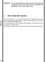
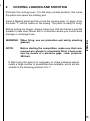
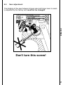
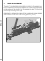
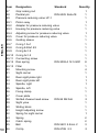
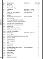
1
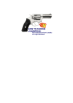
Dear sporting shooter!
The Steyr Match LP 10, caliber 4.5, as built by Steyr Sportwaffen GmbH,
ist a further development of the successful Steyr Match pistol series.
This new high-performance sporting pistol has been designed uncompromisingly with the object to fully exploit the shooter's performance
potential both in competition and training. The most outstanding features of this match pistol are precision, quality and easy handling.
ISSF
Bavariaring 21, D-80336 Munich 2,
Germany.
ENGLISH
Its use is exclusively subject to the "General technical rules" for all
shooting sport disciplines of the INTERNATIONAL SPORT SHOOTING FEDERATION (ISSF).
27
Important rules for the handling of firearms
While it can be assumed that, in general, the shooters are aware of the
following principles they should be stated again fo safety's sake:
All firearms are dangerous objects, storage and use of which demand
utmost caution.
ENGLISH
Always treat an unloaded weapon as if it were loaded.
Never put your finger on the trigger, except when actually firing a shot.
Always ensure that the weapon is pointing in a safe direction. Only
perfect condition of the weapon ensures safety.
Improper handling and lack of care may impair operation and safety of
the pistol. Tampering with its mechanism as well as any damage and
alterations forcibly caused by third persons, will cancel any guarantee
rights towards the manufacturer.
Repairs on the weapon have to be carried out exclusively by authorized specialists.
Weapons always have to be stored out of the reach of unauthorized persons, particularly children and juveniles. Ammunition must
not be stored at the same place as the weapon.
In order to avoid damage to the weapon during transportation the weapon has to be carried in its original packing or in a pistol case (available
as optional equipment from Steyr Sportwaffen GmbH) .
28
2
1
2
3
4
5
5.1
5.2
5.3
5.4
6
6.1
6.2
6.3
6.4
6.5
6.6
7
8
9
9.1
10
11
12
13
14
Technical Data ....................................................................... 30
Special features and advantages ........................................ 31
Dry firing mechanism ........................................................... 32
Cocking, loading and shooting ........................................... 33
Sight adjustment ................................................................... 34
Moving the rearsight ................................................................ 34
Moving front sight .................................................................... 34
Adjusting rear sight plates ...................................................... 35
Checking precision .................................................................. 35
Trigger adjustment ................................................................ 36
Trigger blade adjustment ........................................................ 36
Triggerstop adjustment ........................................................... 37
First stage pressure adjustment ............................................. 38
First stage travel adjustment ................................................... 39
Second stage pressure adjustment ........................................ 40
Sear adjustment ...................................................................... 41
Grip adjustment ..................................................................... 42
Changinging a compressed-air cylinder ............................ 43
Refilling the compressed-air cylinder ................................. 43
Refilling .................................................................................... 44
Accessories ........................................................................... 45
Cleaning and care ................................................................. 45
Guarantee clauses ................................................................ 46
Service .................................................................................... 48
Parts list LP-10 ...................................................................... 49
ENGLISH
Table of Contents
29
1
TECHNICAL DATA
This single shot pistol uses Diabolo bullets cal. 4.5 mm (.177). Dehumidified compressed air is used as propellant.
ENGLISH
Its design corresponds to the state of the art in shooting and was developed in cooperation with renowned top shooters.
Caliber ..........................................................
Overall height ...............................................
Overall lenght ...............................................
Overall width .................................................
Sight length ..................................................
4.5 mm (.177)
142 mm
400 mm
50 mm
adjustable from 319 mm
to 365 mm
Barrel lenght ................................................. 227 mm
Maximum filling pressure ............................. 200 bar
Total weight with filled cylinder .................... 1060 g
Trigger pull weight (adjustable) is
factory-set ..................................................... 500g
(corresponds to ISSF-shooting rules)
Front sight .................................................... 4,5 mm
Number of shots ........................................... appr. 170 shots.
30
2
SPECIAL FEATURES AND ADVANTAGES
Well controlled shooting owing to stabilizer, compensator, and
optional barrel weights.
Bore-holes in the barrel enhance the effectiveness of the compensator and ensure silky soft shooting. The bore-holes also
prevent the weapon from jolting during firing and, in addition,
give you optimal view of the target while firing.
Maximum precision
Extremely short shot release.
The dry firing mechanism at the same time serves as a permanent safety for the hammer.
The compressed air cylinder is easily replaceable without the
use of tools.
The layout of the trigger ensures minimum tilting moment when
firing. Recoil energy is transferred directly into the hand.
Various grip sizes are available for right or left handers.
The palm shelf of the grip is height-adjustable and swivel-mounted.
The grip is adjustable for height and the angle at which it is fitted
to the pistol can be altered.
Rear sight carrier and sight adjusting plate are mounted on
springs and will always return to the position adjusted by the set
screws.
ENGLISH
2
31
WARNING: The enclamped item numbers shown in the following
paragraphs refer to the numbers in the illustration of
the pistol on the inside of the cover.
ENGLISH
3
32
DRY FIRING MECHANISM
The cocking lever (1) is pulled backwards (to a vertical position) and
then moved forward again until you feel the first resistance. The letter
"T" on the casing is still visible.
The mechanism is cocked. Trigger characteristics are realistic and can
be tested for real shooting.
The trigger release noise is audible but no compressed air will escape.
4
4
COCKING, LOADING AND SHOOTING
Pull back the cocking lever (1) to the stop (vertical position), this cocks
the pistol and opens the loading port.
Insert a Diabolo pellet and fully close the cocking lever (1) again. Only
the letter "F" will be visible on the casing. The pistol is ready for firing.
Before pulling the trigger, always make sure that the barrel is pointed
towards a safe area. Never aim in a direction where you could cause
damage or endanger lives.
WARNING: When firing, use ear protection and safety shooting
glasses.
NOTE:
Before starting the competition, make sure that compressed-air cylinder is completely filled. (check pressure by means of a pressure gage - max. pressure:
200 bar).
ENGLISH
4
If after trying the pistol it is necessary to make individual adjustments a large number of possibilities are available, which are described in the following sections 5 to 7.
33
5
SIGHT ADJUSTMENT
Careful firing tests have been carried out with the pistol at the manufacturer' s. Nevertheless, the sight adjustment may not fully suit your
eyes or stance and individual adjustments may be made as follows:
High hit Low hit -
Turn elevation screw (3) in direction "H"
Turn elevation screw (3) in direction "T".
ENGLISH
One notch of the elevation screw changes the impact position by 1,2
mm at a target distance of 10 m.
Right hit Left hit -
Turn lateral adjustment screw in direction "R"
Turn lateral adjustment screw in direction "L"
One notch of the lateral adjustment screw changes the impact position
by 1,2 mm at a target distance of 10 m.
5.1
Moving the rearsight
Loosen screw (5) using Allen key 2.5, move sight carrier to the desired
position and tighten screw (5) again.
5.2
Moving front sight
After loosening the countersunk screw (6) the front sight may be moved
lengthwise. Three positions are available. This allows you to lengthen
or shorten the sighting line.
34
5.3
Adjusting rear sight plates
ENGLISH
The Steyr LP 10 is equipped with anadjustable rear sight, this feature
enables you to adjust sighting width continuously from 0 to 5 mm.
Turning screw (7) clockwise increases the gap between the rear sight
plates, turning screw (8) counter-clockwise reduces the gap and vice
versa.
The depth of the gap is continuously adjustable from 1.8 mm to 2.6
mm.
For this procedure, loosen screws (9). Slide cover plate (2) into desired
position and retighten screws.
7
8
5.4
Checking precision
To check precision with a clamped
weapon, it is advisable to clamp
the pistol around the area of the trigger guard.
Clamp here
35
6
TRIGGER ADJUSTMENT
In the factory the trigger adjustments are set in such a way that the
trigger pulling force corresponds to the ISSF-shooting rules and a
smooth pulling function is ensured. An individual adaptation of the trigger action is possible for optimum individual performance.
It is advisable to make all adjustments with dry fire mechanism engaged.
ENGLISH
Before making any alterations to the trigger, ensure the pistol is unloaded and be sure to read this operator's manual carefully.
6.1
Trigger blade adjustment
The trigger blade may be adjusted for length, height, and angle.
Longitudinal adjustment: Loosen screw (A) and shift blade on the blade
carrier. Retighten screw (A).
Adjustment for height and angle: Loosen screw (B) shift blade vertically or turn it. Retighten screw (B).
A
B
36
6.2
Triggerstop adjustment
Turning the screw clockwise shortens the 'aftertravel' of the trigger
blade after shot release. Turning the screw counter-clockwise lengthens the 'aftertravel' after shot release.
ENGLISH
A too close adjustment may cause unsteady trigger action.
37
First stage pressure adjustment
ENGLISH
6.3
Turning the screw clockwise
increases the first stage
pressure
Turning the screw counter-clockwise
decreases the first stage pressure.
WARNING: Mind total trigger pressure! It is the sum of first stage
pressure plus second stage pressure (also see chapter 6.5).
38
First stage travel adjustment
ENGLISH
6.4
To reduce first stage travel, first loosen the triggerstop screw counterclockwise a few turns.
Turning the screw clockwise shortens first stage travel;
Turning the screw counter-clockwise extends first stage travel.
Re-adjust the triggerstop after adjusting the first stage travel (see 6.2).
39
6.5
Second stage pressure adjustment
ENGLISH
Remove the grip. Loosen screw (10) with Allen key.
Turning screw clockwise increases
the second stage pressure;
Turning screw anticlockwise
decreases the second stage
pressure.
WARNING: Mind total trigger pressure! It is the sum of first stage
pressure plus second stage pressure (also see chapter 6.3)
40
6.6
Sear adjustment
ENGLISH
The bridging of the sear between trigger sear and trigger lever is exactly adjusted by the factory and must not be changed.
Don't turn this screw!
41
7
GRIP ADJUSTMENT
The grip (11) is adjustable and pivotable in relation to the weapon system in all directions and may be adapted over a wide range depending
on the posture of the shooter. For this purpose the grip (11) has to be
removed by loosening screw (10).
42
ENGLISH
Adjustment is achieved by means of the countersunk screws located
at the bottom and the rear of the casing (Allen key, 2 mm).
8
CHANGINGING A COMPRESSED-AIR CYLINDER
The compressed-air cylinder may be unscrewed and removed at any
time even without being emptied.
For refilling the propellantl cylinder the following 'Filling Instruction' must
be exactly adhered to.
REFILLING THE COMPRESSED-AIR CYLINDER
GENERAL:
The legal rules and regulations of the respective country must be adhered to.
WARNING: In compliance with pertaining transportation laws, the
steel cylinders supplied with the pistol are emty.
ENGLISH
9
WARNING: Do not tamper with steel cylinder.
Repair work involving propellant cylinder or valves
may be carried out exclusively by the manufacturer
or persons specifically authorized in writing by the
manufacturer; only original parts may be used.
In case of non-compliance the guarantee shall be void.
The compressed-air cylinder is to be charged with a maximum filling
pressure of 200 bar. This charge will suffice for appr. 170 rounds.
Prior to competition, check pressure by means of a pressure gage!
Refill if pressure is too low.
43
ENGLISH
9.1
Refilling
1.
Dismount cylinder from weapon.
2.
Mount adapter on refill cylinder (standardized thread) and
tighten using a wrench size
27 mm.
3.
Mount compressed-air cylinder on adaptor by hand
(make sure to use only cylinders with a maximum filling
pressure of 200 bar).
Compressedair cylinder
Adapter
4.
Open valve of refill cylinder to charge the compressed-air cylinder with compressed-air (make sure to use only dehumidified
compressed-air).
Close valve of refill cylinder and dismount compressed-air cylinder from adaptor.
5.
Check pressure by means of pressure gage.
WARNING: Since weapon is also functional with low filling pressure, adaquate caution should be exercised!
Do not expose the cylinders to temperatures above
60° C.
The compressed-air cylinder has to be checked ac1212.
cording the local law!
44
10
ACCESSORIES
Standard accessories:
1 compressed-air cylinder with
integrated pressure gage
1 filler adaptor piece
2 O-rings 4x1,5
4 barrel weights
25 g standard grip weight is mounted in the grip.
For shifting the barrel weight notches in distances of 9 mm are provided on the barrel casing. The grip weight (which is already fitted in the
hand rest) may be exchanged after loosening the two lateral head cap
socket screws.
11
ENGLISH
The barrel weights are mounted on the barrel
casing and may be shifted along the barrel.
CLEANING AND CARE
During normal shooting the pistol is maintenance-free and need not be
greased. However, it is advisable to slightly grease the two O-rings in
the loading port and the O-ring at the threaded adaptor socket for the
propellant cylinder with a special lubricant (acid-free silicone grease)
every 1000 shots. This will increase the service life of the O-rings.
In addition, it is recommended to wipe the pistol with a soft cloth after
use. The visible metal parts may be slightly oiled from time to time with
a good gun oil. To clean the barrel shoot some dry (not greased) felt
pellets through the barrel.
45
12
GUARANTEE CLAUSES
These guarantee clauses do not apply to the USA.
If within one year from the day of purchase any cracks or breaks should
occur on this weapon that are due to material failure we undertake to
repair the defective parts free of charge.
ENGLISH
The Steyr Sportwaffen guarantee may be claimed only by the first owner and only under the following conditions:
Guarantee will be given by either replacing or repairing the weapon or
individual parts of it at our sole discretion. Any costs for material and/or
working time shall be borne by us. Neither rescission of sale nor reduction may be claimed.
lf during the period of guarantee material failure or improper weapon
function should occur repeatedly, any guarantee claims have to be
submitted without delay, at the latest, however, within a period of one
month.
Only authorized Steyr Sportwaffen dealers, authorized Steyr Sportwaffen
service workshops and the Steyr Sportwaffen GmbH may accept guarantee claims.
The customer shall bear any cost and the risk of loss or damage of the
weapon on the way to the agency authorized to accept guarantee claims.
The costs for returning the repaired weapon or replaced parts to the
customers shall be borne by the Steyr Mannlicher AG & Co KG unless
otherwise agreed.
Please return the fully completed Steyr Sportwaffen guarantee card
to the manufacturer within ten (10) days after purchase of the
weapon. In case of a guarantee claim the weapon has to be submitted along with the Steyr Sportwaffen guarantee card .
46
a.
if the weapon has been damaged or destroyed by force majeur or environmental influences;
b.
in case damages/defects have been caused by improper treatment, or handling or by inadequate maintenance;
c.
if the weapon has been repaired, worked on or altered by any
person or workshop other than an authorized Steyr Sportwaffen
workshop;
Claims for damages and product liability
No claims for direct or indirect damage will be accepted.
Liability for material damageas defined in the product liability law,as
well as any product liability claims that could be derived from other
provisions are exciuded.
ENGLISH
No guarantee claims will be accepted by the Steyr Sportwaffen
GmbH or their agencies:
The object of purchase warrants only that type of safety which may be
expected in accordance with the homologation rules , service manual,
manufacturer’s instructions as to the treatment of the supplied object
(Operater's Manual) as well as any other pertinent information received.
The above provisions shall fully govern the legal relationship with our
company. Any additional claims, in particular for any kind of damage or
losses caused by the weapon or its use, are excluded. Any claims
against the Steyr Sportwaffen dealer as seller are excluded, if and to
the extent as we give satisfaction.
47
Steyr Sportwaffen accuracy guarantee
Steyr Sportwaffen barrels are made from high-quality barrel steel and
are produced according to the latest findings in barrel production technology.
Our weapons are well known for their outstanding performance.
However, the accuracy of a weapon depends on several factors, one of
the most important factors being the ammunition used. Not every type
of ammunition is suitable for a given type of barrel.
ENGLISH
Even ammunition of the same manufacturer and of the same brand
may show different accuracy results from batch to batch and when
fired from different weapons.
With optimal ammunition we guarantee excellent accuracy of our weapons.
Claims regarding insufficient accuracy must be reported to us in writing within twenty (20) days after purchase of the weapon. Should accuracy test show that the claim was unfounded, we reserve the right to
charge the costs of the test and for shipping to the claimant.
13
SERVICE
Your air pistol has been thoroughly and very carefully tested before
delivery.
Should it become necessary to replace parts or to carry out repairs on
the weapon please contact anauthorized Steyr Sportwaffen dealer.
WARNING: Only genuine spare parts may be used!
48
Item
1
2
2.1
2.2
2.3
2.4
3
4
5
6
7
8
9
10
11
12
13
14
15
16
17
18
19
20
21
22
23
24
25
26
PARTS LIST LP-10
Designation
Barrel LP-10
Barrel casing LP-10, assy
Barrel casing LP-10
Compensator LP-10
Hexagon socket set screw
Hexagon socket set screw
Hexagon socket set screw
Front sight 4.5 mm
Countersunk screw
Barrel weight assy
O-ring 6x2
Barrel weight
Screw lock
Hexagon socket set screw
Hexagon socket set screw
Casing LP-10
O-ring 18x2
Hexagon socket set screw
Cam
Cam screw
Pressure spring
Valve assy
Hammer LP-10
Set screw V0
Threaded bushing
Cocking lever
Cocking lever handle
Stop screw
Parallel pin
Hex. socket countersunk
head screw
Standard
Quantity
1
1
1
1
DIN 913 M 3x3
1
DIN 913 M 5x5
1
DIN 913 M3x3
1
1
1
1
3
4
4
DIN 914 M3x4
1
DIN 913 M3x5
4
1
1
DIN 914 M5x6
2
1
1
1
1
1
1
1
1
1
1
DIN 6325 2m6x18
4
DIN 7991 M3x8
8
ENGLISH
14
49
ENGLISH
50
Item
27
28
29
29.1
29.2
29.3
29.4
29.5
29.6
29.7
29.8
29.9
29.10
29.11
29.12
29.13
30
31
32
33
34
35
36
37
38
39
40
41
42
43
44
45
46
Designation
Standard
Quantity
Grip locking rod
1
Parallel pin
DIN 6325 3m6x18
1
Pressure reducing valve LP-1
1
Piston assy
1
Adapter for pressure reducing valve
1
Housing for pressure reducing valve
1
Adjusting screw for pressure reducing valve
1
Cover for pressure reducing valve
1
Guiding sleeve
1
O-ring 1.5x1
1
O-ring 8.92x1.83
1
O-ring 4x1.5
1
O-ring 3x1.5
1
Connecting screw
1
Disc spring
DIN 2093 A 12.5 GR1
8
Filter
1
Mounting screw
4
Sight carrier
1
Rear sight plate right
1
Rear sight plate left
1
Spindle, right
1
Spindle, left
1
Fixing clamp
1
Cover plate
1
Slotted cheese head screw
DIN 84 M2.5x5
2
Sight yoke
1
Sliding block
1
Height adjusting screw
1
Spring for sight carrier
1
Spring
2
Catch spring
2
Ball
DIN 5401 2.5mm V
3
Circlip
DIN 6799 2.3
2
58.5
58.6
58.7
59
60
61
Designation
Lateral adjusting screw
Sight plate LP-10
Screw for sight plate
Washer
Spring
Pressure spring
First stage pressure spring
Spring
Trigger blade carrier assy
Trigger blade carrier
Screw lock
Screw lock
First stage pressure adjusting
Slotted set screw
Slotted headless screw
Trigger lever assy
Trigger lever
First stage pressure adjusting
Slotted headless screw
Screw lock
Trigger sear
Trigger complete
Trigger mount assy
Trigger pin
Trigger blade
Slotted raised countersunk
head screw
Hexagon socket set screw
Hexagon socket set screw
Disc spring
Bolt LP-10
Stabilizer LP-10
Catch lever
Standard
Quantity
1
1
1
DIN 125 A 4.3
1
1
1
1
1
1
1
1
1
screw
1
DIN 551 M3x10
1
DIN926 M3x0.35x6x2.5 1
1
1
screw
1
DIN926 M3x0.35x6x2.5 1
1
1
1
1
1
1
DIN 964 M3x8
1
DIN 913 M3x5
DIN 913 M3x3
DIN 2093 A10 GR1
1
1
3
1
1
1
ENGLISH
Item
47
48
49
50
51
52
53
54
55
55.1
55.2
55.3
55.4
55.5
55.6
56
56.1
56.2
56.3
56.4
57
58
58.1
58.2
58.3
58.4
51
ENGLISH
Item
62
63
64
65
66
67
52
Designation
Standard
Quantity
Bolt roller
1
Guide ring
1
Pressure spring
1
Parallel pin
DIN 6325 1,5m6x7
1
Ball
DIN 5401 2mm III
1
Cross rec. countersunk
DIN 965 M3x5
1
head screw
68
Spring
4
69
Hexagon socket set screw
DIN 913 M3x8
1
70
O-ring 3x1.6
1
71
O-ring 5x1.5 FPM70 or FPM81
1
72
Propellant cylinder compressed air
1
72.1
Cylinder body compressed air
1
72.2
Cylinder valve compressed air
1
72.3
Valve head
1
72.4
Trigger adjusting spring
1
72.5
Cylinder valve tappet assy
1
72.5.1 Cylinder valve tappet
1
72.5.2 Parallel pin
DIN 6325 2m6x16
1
72.6
O-ring 20x2
1
72.7
Valve body for pressure reducing valve
1
72.8
O-ring 2.9x1.9
1
72.9
Supporting ring
1
73
Grip, complete
1
73.1
Grip
1
73.2
Palm shelf
1
73.3
SMG- label
1
73.4
Slotted cheese head screw
M5x35 8.8 A2R
3
73.5
Grip weight 25 g
1
73.6
Distance plate
1
73.7
Rest plate
1
73.8
O-ring 4x1.5
1
73.9
Washer 5.3
1
74
Sight carrier assy
1
11
5
8
8
9
11
6
4
9
45
39
3
2.3
42
1
46
6
47
ST
2
EY
29.9
30
LP-10
2.2
29.5
29.7
R-S
25
2.1
PO
RT
29.11
WA
31
29.13
45
44
FF
EN
45
29.4
40
29.10
41
29.11
2.4
34
44
43
74
32
49
36
46
73
37
29.2
14
51
61
68
7
29.12
72.2
50
43
18
29.6
33
35
73.7
38
66
STE
YR
71
12
LP-
72.3
10
48
59
65
67
-SP
OR
TW
AU AFF
STR EN
IA
29.1
29.8
F
72.5.1
10
T
73.6
69
62
64
63
73.1
68
73.4
70
72.4
72.9
25
29.3
72.6
21
15
26
68
16
28
22
72.1
20
52
72.7
72.8
72.5
19
13
29
72.5.2
60
73.3
53
55
23
17
26
54
7
24
26
25
55.1
55.4
58.4
56
27
73.2
73.8
73.9
56.2
55.3
58.1
56.4
58.7
72
58
58.5
73.4
58.6
58.3
58.2
57
55.6
55.2
55.5
56.3
56.1
73.5