1
SVM 122-A
TM
IDEALARC DC-400
Oct. 1996
For use with machine code numbers 9847, 9848 and 9850
Safety Depends on You
Lincoln arc welding and cutting
equipment is designed and built
with safety in mind. However,
your overall safety can be
increased by proper installation
. . . and thoughtful operation on
your part. DO NOT INSTALL,
OPERATE OR REPAIR THIS
EQUIPMENT WITHOUT READING THIS MANUAL AND THE
SAFETY PRECAUTIONS CONTAINED THROUGHOUT. And,
most importantly, think before
you act and be careful.
SERVICE MANUAL
LINCOLN
World’s Leader in Welding and Cutting Products
ELECTRIC
®
Premier Manufacturer of Industrial Motors
Sales and Service through subsidiaries and Distributors Worldwide
22801 St. Clair Ave. Cleveland, Ohio 44117-1199 U.S.A. Tel. (216) 481-8100
i
i
SAFETY
WARNING
CALIFORNIA PROPOSITION 65 WARNINGS
Diesel engine exhaust and some of its constituents
are known to the State of California to cause cancer, birth defects, and other reproductive harm.
The Above For Diesel Engines
The engine exhaust from this product contains
chemicals known to the State of California to cause
cancer, birth defects, or other reproductive harm.
The Above For Gasoline Engines
ARC WELDING CAN BE HAZARDOUS. PROTECT YOURSELF AND OTHERS FROM POSSIBLE SERIOUS INJURY OR DEATH.
KEEP CHILDREN AWAY. PACEMAKER WEARERS SHOULD CONSULT WITH THEIR DOCTOR BEFORE OPERATING.
Read and understand the following safety highlights. For additional safety information, it is strongly recommended that you
purchase a copy of “Safety in Welding & Cutting - ANSI Standard Z49.1” from the American Welding Society, P.O. Box 351040,
Miami, Florida 33135 or CSA Standard W117.2-1974. A Free copy of “Arc Welding Safety” booklet E205 is available from the
Lincoln Electric Company, 22801 St. Clair Avenue, Cleveland, Ohio 44117-1199.
BE SURE THAT ALL INSTALLATION, OPERATION, MAINTENANCE AND REPAIR PROCEDURES ARE
PERFORMED ONLY BY QUALIFIED INDIVIDUALS.
FOR ENGINE
powered equipment.
1.h. To avoid scalding, do not remove the
radiator pressure cap when the engine is
hot.
1.a. Turn the engine off before troubleshooting and maintenance
work unless the maintenance work requires it to be running.
____________________________________________________
1.b.Operate engines in open, well-ventilated
areas or vent the engine exhaust fumes
outdoors.
____________________________________________________
1.c. Do not add the fuel near an open flame welding arc or when the engine is running. Stop
the engine and allow it to cool before refueling to prevent spilled fuel from vaporizing on
contact with hot engine parts and igniting. Do
not spill fuel when filling tank. If fuel is spilled,
wipe it up and do not start engine until fumes
have been eliminated.
____________________________________________________
1.d. Keep all equipment safety guards, covers
and devices in position and in good
repair.Keep hands, hair, clothing and tools
away from V-belts, gears, fans and all other
moving parts when starting, operating or
repairing equipment.
____________________________________________________
ELECTRIC AND
MAGNETIC FIELDS
may be dangerous
2.a. Electric current flowing through any conductor causes
localized Electric and Magnetic Fields (EMF). Welding
current creates EMF fields around welding cables and
welding machines
2.b. EMF fields may interfere with some pacemakers, and
welders having a pacemaker should consult their physician
before welding.
2.c. Exposure to EMF fields in welding may have other health
effects which are now not known.
2.d. All welders should use the following procedures in order to
minimize exposure to EMF fields from the welding circuit:
2.d.1. Route the electrode and work cables together - Secure
them with tape when possible.
1.e. In some cases it may be necessary to remove safety
guards to perform required maintenance. Remove
guards only when necessary and replace them when the
maintenance requiring their removal is complete.
Always use the greatest care when working near moving
parts.
___________________________________________________
1.f. Do not put your hands near the engine fan. Do not attempt to
override the governor or idler by pushing on the throttle control rods while the engine is running.
___________________________________________________
1.g. To prevent accidentally starting gasoline engines while
turning the engine or welding generator during maintenance
work, disconnect the spark plug wires, distributor cap or
magneto wire as appropriate.
2.d.2. Never coil the electrode lead around your body.
2.d.3. Do not place your body between the electrode and
work cables. If the electrode cable is on your right
side, the work cable should also be on your right side.
2.d.4. Connect the work cable to the workpiece as close as
possible to the area being welded.
2.d.5. Do not work next to welding power source.
IDEALARC DC-400
LINCOLN
ELECTRIC
®
ii
ii
SAFETY
ELECTRIC SHOCK can kill.
ARC RAYS can burn.
3.a. The electrode and work (or ground) circuits
are electrically “hot” when the welder is on.
Do not touch these “hot” parts with your bare
skin or wet clothing. Wear dry, hole-free
gloves to insulate hands.
4.a. Use a shield with the proper filter and cover
plates to protect your eyes from sparks and
the rays of the arc when welding or observing
open arc welding. Headshield and filter lens
should conform to ANSI Z87. I standards.
3.b. Insulate yourself from work and ground using dry insulation.
Make certain the insulation is large enough to cover your full
area of physical contact with work and ground.
4.b. Use suitable clothing made from durable flame-resistant
material to protect your skin and that of your helpers from
the arc rays.
In addition to the normal safety precautions, if welding
must be performed under electrically hazardous
conditions (in damp locations or while wearing wet
clothing; on metal structures such as floors, gratings or
scaffolds; when in cramped positions such as sitting,
kneeling or lying, if there is a high risk of unavoidable or
accidental contact with the workpiece or ground) use
the following equipment:
• Semiautomatic DC Constant Voltage (Wire) Welder.
• DC Manual (Stick) Welder.
• AC Welder with Reduced Voltage Control.
4.c. Protect other nearby personnel with suitable, non-flammable
screening and/or warn them not to watch the arc nor expose
themselves to the arc rays or to hot spatter or metal.
FUMES AND GASES
can be dangerous.
5.a. Welding may produce fumes and gases
hazardous to health. Avoid breathing these
fumes and gases.When welding, keep
your head out of the fume. Use enough
ventilation and/or exhaust at the arc to keep
fumes and gases away from the breathing zone. When
welding with electrodes which require special
ventilation such as stainless or hard facing (see
instructions on container or MSDS) or on lead or
cadmium plated steel and other metals or coatings
which produce highly toxic fumes, keep exposure as
low as possible and below Threshold Limit Values (TLV)
using local exhaust or mechanical ventilation. In
confined spaces or in some circumstances, outdoors, a
respirator may be required. Additional precautions are
also required when welding on galvanized steel.
3.c. In semiautomatic or automatic wire welding, the electrode,
electrode reel, welding head, nozzle or semiautomatic
welding gun are also electrically “hot”.
3.d. Always be sure the work cable makes a good electrical
connection with the metal being welded. The connection
should be as close as possible to the area being welded.
3.e. Ground the work or metal to be welded to a good electrical
(earth) ground.
3.f. Maintain the electrode holder, work clamp, welding cable and
welding machine in good, safe operating condition. Replace
damaged insulation.
3.g. Never dip the electrode in water for cooling.
3.h. Never simultaneously touch electrically “hot” parts of
electrode holders connected to two welders because voltage
between the two can be the total of the open circuit voltage
of both welders.
3.i. When working above floor level, use a safety belt to protect
yourself from a fall should you get a shock.
3.j. Also see Items 6.c. and 8.
5.b. Do not weld in locations near chlorinated hydrocarbon vapors
coming from degreasing, cleaning or spraying operations.
The heat and rays of the arc can react with solvent vapors to
form phosgene, a highly toxic gas, and other irritating
products.
5.c. Shielding gases used for arc welding can displace air and
cause injury or death. Always use enough ventilation,
especially in confined areas, to insure breathing air is safe.
5.d. Read and understand the manufacturer’s instructions for this
equipment and the consumables to be used, including the
material safety data sheet (MSDS) and follow your
employer’s safety practices. MSDS forms are available from
your welding distributor or from the manufacturer.
5.e. Also see item 1.b.
IDEALARC DC-400
LINCOLN
ELECTRIC
®
iii
iii
SAFETY
WELDING SPARKS can
cause fire or explosion.
CYLINDER may explode
if damaged.
6.a. Remove fire hazards from the welding area.
If this is not possible, cover them to prevent
the welding sparks from starting a fire.
Remember that welding sparks and hot
materials from welding can easily go through small cracks
and openings to adjacent areas. Avoid welding near
hydraulic lines. Have a fire extinguisher readily available.
6.b. Where compressed gases are to be used at the job site,
special precautions should be used to prevent hazardous
situations. Refer to “Safety in Welding and Cutting” (ANSI
Standard Z49.1) and the operating information for the
equipment being used.
7.a. Use only compressed gas cylinders
containing the correct shielding gas for the
process used and properly operating
regulators designed for the gas and
pressure used. All hoses, fittings, etc. should be suitable for
the application and maintained in good condition.
7.b. Always keep cylinders in an upright position securely
chained to an undercarriage or fixed support.
7.c. Cylinders should be located:
• Away from areas where they may be struck or subjected to
physical damage.
6.c. When not welding, make certain no part of the electrode
circuit is touching the work or ground. Accidental contact can
cause overheating and create a fire hazard.
6.d. Do not heat, cut or weld tanks, drums or containers until the
proper steps have been taken to insure that such procedures
will not cause flammable or toxic vapors from substances
inside. They can cause an explosion even though they have
been “cleaned”. For information, purchase “Recommended
Safe Practices for the Preparation for Welding and Cutting of
Containers and Piping That Have Held Hazardous
Substances”, AWS F4.1 from the American Welding Society
(see address above).
6.e. Vent hollow castings or containers before heating, cutting or
welding. They may explode.
6.f. Sparks and spatter are thrown from the welding arc. Wear oil
free protective garments such as leather gloves, heavy shirt,
cuffless trousers, high shoes and a cap over your hair. Wear
ear plugs when welding out of position or in confined places.
Always wear safety glasses with side shields when in a
welding area.
6.g. Connect the work cable to the work as close to the welding
area as practical. Work cables connected to the building
framework or other locations away from the welding area
increase the possibility of the welding current passing
through lifting chains, crane cables or other alternate circuits.
This can create fire hazards or overheat lifting chains or
cables until they fail.
6.h. Also see item 1.c.
• A safe distance from arc welding or cutting operations and
any other source of heat, sparks, or flame.
7.d. Never allow the electrode, electrode holder or any other
electrically “hot” parts to touch a cylinder.
7.e. Keep your head and face away from the cylinder valve outlet
when opening the cylinder valve.
7.f. Valve protection caps should always be in place and hand
tight except when the cylinder is in use or connected for
use.
7.g. Read and follow the instructions on compressed gas
cylinders, associated equipment, and CGA publication P-l,
“Precautions for Safe Handling of Compressed Gases in
Cylinders,” available from the Compressed Gas Association
1235 Jefferson Davis Highway, Arlington, VA 22202.
FOR ELECTRICALLY
powered equipment.
8.a. Turn off input power using the disconnect
switch at the fuse box before working on
the equipment.
8.b. Install equipment in accordance with the U.S. National
Electrical Code, all local codes and the manufacturer’s
recommendations.
8.c. Ground the equipment in accordance with the U.S. National
Electrical Code and the manufacturer’s recommendations.
IDEALARC DC-400
LINCOLN
ELECTRIC
®
iv
SAFETY
7. Quand on ne soude pas, poser la pince à une endroit isolé
de la masse. Un court-circuit accidental peut provoquer un
échauffement et un risque d’incendie.
PRÉCAUTIONS DE SÛRETÉ
Pour votre propre protection lire et observer toutes les instructions
et les précautions de sûreté specifiques qui parraissent dans ce
manuel aussi bien que les précautions de sûreté générales suivantes:
8. S’assurer que la masse est connectée le plus prés possible
de la zone de travail qu’il est pratique de la faire. Si on place
la masse sur la charpente de la construction ou d’autres
endroits éloignés de la zone de travail, on augmente le
risque de voir passer le courant de soudage par les chaines
de levage, câbles de grue, ou atres circuits. Cela peut
provoquer des risques d’incendie ou d’echauffement des
chaines et des câbles jusqu’à ce qu’ils se rompent.
Sûreté Pour Soudage A L’Arc
1.
iv
Protegez-vous contre la secousse électrique:
a.
b.
Les circuits à l’électrode et à la piéce sont sous tension
quand la machine à souder est en marche. Eviter toujours tout contact entre les parties sous tension et la
peau nue ou les vétements mouillés. Porter des gants
secs et sans trous pour isoler les mains.
Faire trés attention de bien s’isoler de la masse quand
on soude dans des endroits humides, ou sur un plancher metallique ou des grilles metalliques, principalement
dans les positions assis ou couché pour lesquelles une
grande partie du corps peut être en contact avec la
masse.
c.
Maintenir le porte-électrode, la pince de masse, le câble
de soudage et la machine à souder en bon et sûr état
defonctionnement.
d.
Ne jamais plonger le porte-électrode dans l’eau pour le
refroidir.
e.
Ne jamais toucher simultanément les parties sous tension des porte-électrodes connectés à deux machines à
souder parce que la tension entre les deux pinces peut
être le total de la tension à vide des deux machines.
2.
Dans le cas de travail au dessus du niveau du sol, se protéger
contre les chutes dans le cas ou on recoit un choc. Ne jamais
enroule le câble-électrode autour de n’importe quelle partie
du corps.
3.
Un coup d’arc peut être plus sévère qu’un coup de soliel,
donc:
a.
Utiliser un bon masque avec un verre filtrant approprié
ainsi qu’un verre blanc afin de se protéger les yeux du
rayonnement de l’arc et des projections quand on soude
ou quand on regarde l’arc.
b.
Porter des vêtements convenables afin de protéger la
peau de soudeur et des aides contre le rayonnementde
l’arc.
c.
Protéger l’autre personnel travaillant à proximité au
soudage à l’aide d’écrans appropriés et non-inflammables.
4.
Des gouttes de laiter en fusion sont émises de l’arc de
soudage. Se protéger avec es vêtements de protection libres
de l’huile, tels que les gants en cuir, chemise épaisse, pantalons sans revers, et chaussures montantes.
5.
Toujours porter des lunettes de sécurité dans la zone de
soudage. Utiliser des lunettes avec écrans lateraux dans les
zones où l’on pique le laitier.
6.
Eloigner les matériaux inflammables ou les recouvrir afin de
prévenir ttout risque d’incendie dû étincelles.
9. Assurer une ventilation suffisante dans la zone de soudage.
Ceci est particuliérement important pour le soudage de tôles
galvanisées plombées, ou cadmiées ou tout autre métal qui
produit des fumées toxiques.
10. Ne pas souder en présence de vapeurs de chlore provenant
d’opéerations de dégraissage, nettoyage ou pistolage. La
chaleur ou les rayons de l’arc peuvent réagir avec les
vapeurs du solvant pour produire du phosgéne (gas fortement roxique) ou autres produits irritants.
PRÉCAUTIONS DE SÛRETÉ POUR LES
MACHINES À SOUDER À TRANSFORMATEUR ET À REDRESSEUR
1.
Relier à la terre le chassis du poste conformement au code
de l’électricité et aux recommendations du fabricant. Le dispositif de montage ou la piece à souder doit être branché à
une bonne mise à la terre.
2.
Autant que possible, l’installation et l’entretien du poste
seront effectués par un électricien qualifié.
3.
Avant de faires des travaux à l’interieur de poste, la
debrancher à l’interrupteur à la boite de fusibles.
4.
Garder tous les couvercles et dispostifis de sûreté à leur
place.
IDEALARC DC-400
LINCOLN
ELECTRIC
®
v
v
MASTER TABLE OF CONTENTS FOR ALL SECTIONS
Page
Safety.................................................................................................................................................i-iv
Installation .............................................................................................................................Section A
Installation Section Table of Contents ........................................................................................A-1
Technical Specifications .............................................................................................................A-2
Safety Precautions......................................................................................................................A-3
Select Suitable Location (Stacking, Tilting, Lifting) ....................................................................A-3
Input Connections.......................................................................................................................A-4
Reconnect Procedure .................................................................................................................A-6
Output Connections....................................................................................................................A-7
Operation...............................................................................................................................Section B
Safety Instructions ......................................................................................................................B-2
General Description ....................................................................................................................B-3
Controls and Settings .................................................................................................................B-4
Welding Operation ......................................................................................................................B-6
Overload Protection....................................................................................................................B-9
Auxiliary Power ...........................................................................................................................B-9
Accessories...........................................................................................................................Section C
Maintenance .........................................................................................................................Section D
Safety Precautions......................................................................................................................D-2
Routine and Periodic Maintenance ............................................................................................D-2
General Component Locations...................................................................................................D-3
Theory of Operation .............................................................................................................Section E
Troubleshooting and Repair.................................................................................................Section F
How To Use Troubleshooting Guide ...........................................................................................F-2
Troubleshooting Guide ................................................................................................................F-4
Test Procedures ........................................................................................................................F-15
Oscilloscope Waveforms ..........................................................................................................F-33
Replacement Procedures..........................................................................................................F-40
Retest After Repair....................................................................................................................F-61
Electrical Diagrams ..............................................................................................................Section G
Parts Manual.................................................................................................................................P-234
IDEALARC DC-400
LINCOLN
ELECTRIC
®
Section A-1
TABLE OF CONTENTS
- INSTALLATION SECTION -
Section A-1
Installation
Technical Specifications Idealarc DC-400 ..................................................................................A-2
Input and Output Specifications ..........................................................................................A-2
Cable and Fuse Sizes...........................................................................................................A-2
Physical Dimensions ............................................................................................................A-2
Safety Precautions......................................................................................................................A-3
Select Suitable Location .............................................................................................................A-3
Lifting .................................................................................................................................A-3
Tilting .................................................................................................................................A-3
Stacking................................................................................................................................A-3
Input Connections.......................................................................................................................A-4
Ground Connection ..............................................................................................................A-4
Input Supply Connections....................................................................................................A-4
Input Wire and Fuse Size ...............................................................................................A-5
Reconnect Procedure .................................................................................................................A-6
Output Connections....................................................................................................................A-7
Wire Feeder Connections.....................................................................................................A-8
Connections for Stick, TIG, Air/carbon Arc Operations.......................................................A-8
IDEALARC DC-400
LINCOLN
ELECTRIC
®
A-2
A-2
INSTALLATION
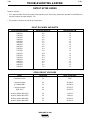
TECHNICAL SPECIFICATIONS - IDEALARC DC-400
INPUT - THREE PHASE ONLY
Standard Voltage
Input Current @ Rated Output
208V
230V
460V
575V
87A
78A
39A
32A
RATED OUTPUT
Duty Cycle
Amps
Volts at Rated Amps
100%
60%
50%
400
450
500
36
38
40
OUTPUT
Mode
Current
Range
Maximum Open
Circuit Voltage
Auxiliary Power
Constant Current
Constant Voltage
60 to 500 Amps
60 to 500 Amps
57 VDC
45.5 VDC
115 VAC, 10 Amps
42 VAC, 10 Amps
RECOMMENDED INPUT WIRE AND FUSE SIZES
Input Voltage /
Frequency
Fuse
(Super Lag)
or Breaker Size
Input Ampere
Rating on
Nameplate
Input Wire Size
Type 75°C
Copper Wire in
Conduit AWG
(IEC) Sizes
Ground Wire Size
Type 75°C
Copper Ground
Wire in Conduit
AWG (IEC) Sizes
125
125
60
125
125
70
70
60
87
78
39
81
77
47
44
41
4 (21 mm2)
4 (21 mm2)
8 (8.4 mm2)
4 (21 mm2)
4 (21 mm2)
8 (8.4 mm2)
8 (8.4 mm2)
8 (8.4 mm2)
6 (13 mm2)
6 (13 mm2)
10 (5.3 mm2)
6 (13 mm2)
6 (13 mm2)
8 (8.4 mm2)
8 (8.4 mm2)
10 (5.3 mm2)
Volts/Hz
208/60
230/60
460/60
220/50/60
230/50/60
380/50/60
400/50/60
440/50/60
PHYSICAL DIMENSIONS
Height
Width
Depth
Weight
30.75 in.
(781 mm)
22.25 in.
(565 mm)
32 in.
(813 mm)
473 lbs.
(215 kg)
IDEALARC DC-400
LINCOLN
ELECTRIC
®
A-3
A-3
INSTALLATION
Read this entire installation section before you
start installation.
LIFTING
WARNING
SAFETY PRECAUTIONS
FALLING EQUIPMENT can cause
injury.
WARNING
• Do not lift this machine using the
lift bail if it is equipped with a heavy
accessory such as a trailer or a gas
cylinder.
ELECTRIC SHOCK can kill.
• Do not touch electrically live
parts or electrodes with your
skin or wet clothing.
• Insulate yourself from the work
and ground.
• Always wear dry insulating gloves.
• Lift only with equipment of adequate lifting capacity.
• Be sure the machine is stable when lifting.
• Do not stack more than three high.
• Do not stack the DC-400 on top of any other
machine.
Only qualified personnel should install, use, or service this equipment.
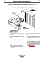
SELECT SUITABLE LOCATION
Place the Idealarc DC-400 where clean, cooling air can
flow freely in through the front louvers and out through
the rear louvers. Keep dust, dirt, and other foreign
materials that can be drawn into the machine to a minimum. Failure to observe these precautions can lead
to excessive operating temperatures and nuisance
shut-downs.
The Idealarc DC-400 weighs 473 pounds (215 kilograms). A permanent lift bail is located at the top of
the machine, positioned at the center of gravity for stable lifting.
TILTING
Place the machine on a secure, level surface. Any surfaces you place it on other than the ground must be
firm, non-skid, and structurally sound.
STACKING
Idealarc DC-400s may be stacked three high. The
bottom machine must be on a stable, hard, level surface capable of supporting the weight of up to three
machines (1419 pounds/645 kilograms). Be sure that
the two pins in the roof of the bottom machine fit into
the holes in the base of the machine above. The lift
bail is positioned so that it fits without interference
under the base of the second machine.
A-4
A-4
INSTALLATION
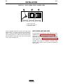
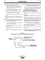
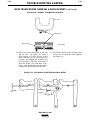
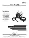
INPUT CONNECTIONS
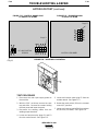
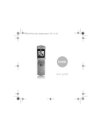
Input supply line entry is through a hole in the case
rear top panel. A removable door covers the input
connection box, which contains the input contactor
(CR1) and r econnect panel assembly for multiple voltage machines. Input power is connected to the three
line terminals on the input contactor. See Figure A.2.
Be sure the voltage, phase, and frequency of the
input power is as specified on the rating plate, located on the case front control panel. See Figure
A.1.
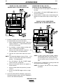
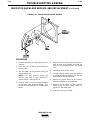
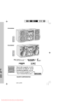
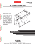
FIGURE A.2 Ð REARPANEL
FIGURE A.1 Ð RATING PLATE LOCATION
1. INPUT SUPPLY LINE ENTR Y HOLE
2. INPUT CONTACTOR CR1
3. RECONNECT P ANEL
1. RATING PLATE
GROUND CONNECTION
The frame of the welder must be grounded. An earth
grounding lead must be connected to the grounding
terminal, marked on the input box floor with the symbol (
).
WARNING
ELECTRIC SHOCK can kill.
¥ Have a qualified electrician
install and service this equipment.
INPUT SUPPLY CONNECTIONS
¥ Turn the input power off at the
fuse box before working on this
equipment.
Be sure the voltage, phase, and frequency of the input
power is as specified on the rating plate.
¥ Do not touch electrically hot
parts.
¥ Insulate yourself from the work and ground.
¥ Always wear dry insulating gloves.
IDEALARC DC-400
LINCOLN
ELECTRIC
¨
A-5
INSTALLATION
A-5
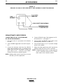
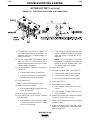
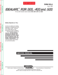
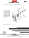
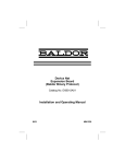
FIGURE A.3 – INPUT POWER SUPPLY CONNECTIONS
1. INPUT SUPPLY LINE
2. INPUT CONTACTOR CR1
3. RECONNECT PANEL
Have a qualified electrician connect the input power
leads to the L1, L2, and L3 terminals of the input contactor. Follow all national and local electrical codes.
Use a three-phase line. Refer to the connection diagram located on the inside cover of the access panel
cover. Also see Figure A.3.
INPUT WIRE AND FUSE SIZE
Fuse the input circuit with the super lag fuses recommended on the Technical Specifications page or use
delay type circuit breakers. Choose an input and
grounding wire size according to local or national
codes; also see the Technical Specifications page.
Using fuses or circuit breakers smaller than recommended may result in “nuisance” shut-offs from
welder inrush currents, even if you are not welding at
high currents.
A-6
A-6
INSTALLATION
RECONNECT PROCEDURE
Multiple input voltage welders are shipped connected
for the highest voltage listed on the machine’s rating
plate. Before installing the welder, be sure the reconnect panel is connected for the proper voltage.
To reconnect a multiple voltage machine to a different
voltage, remove input power. Follow the input connection diagram, located on the inside access panel
cover, appropriate for your machine’s input voltage.
These same connection diagrams are shown below.
For 208, 208/230 & 230/460 volts AC - see Figure A.4.
For 230/460/575 volts AC - see Figure A.5.
CAUTION
Failure to follow these instructions can cause immediate failure of components in the welder.
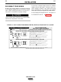
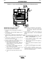
FIGURE A.4 - INPUT CONNECTION DIAGRAM FOR 208, 208/230 and 230/460 VOLTS AC, 50/60 HZ
Do not operate with covers
removed
Disconnect input power before
servicing
DUAL VOLTAGE MACHINE
INPUT SUPPLY CONNECTION DIAGRAM
Do not touch electrically live parts
Only qualified persons should install,
use or service this equipment
IMPORTANT: CHANGE LINK POSITIONS AND PILOT TRANSFORMER CONNECTIONS.
NOTE: MACHINES ARE SHIPPED FROM FACTORY CONNECTED FOR OVER 300 VOLTS
CONNECTION FOR HIGHEST RATING PLATE VOLTAGE, 50 OR 60 HZ.
LINK
1. TURN OFF THE INPUT POWER USING THE DISCONNECT SWITCH AT THE FUSE BOX.
{
LINES
INPUT
L3
W CR1
2. DISCONNECT AND INSULATE THE H2 LEAD TERMINAL WITH TAPE TO PROVIDE AT
LEAST 600 VOLT INSULATION.
L2
V
3. CONNECT L1, L2 & L3 INPUT SUPPLY LINES AND H3 TRANSFORMER LEADS
TO THE INPUT SIDE OF THE CR1 CONTACTOR AS SHOWN.
CONTACTOR
L1
GND
U
H3
H1
4. CONNECT TERMINAL MARKED
CODES.
H2
TO GROUND PER LOCAL AND NATIONAL ELECTRIC
5. MOUNT THE LINKS IN THE POSITIONS SHOWN WITH THE PROVIDED HEX NUTS.
DOUBLE UP THE LINKS IN TWO OF THE POSITIONS TO SAVE THEM FOR FUTURE
USE. SECURE THE REMAINING HEX NUTS IN PLACE.
PILOT
TRANSF.
CONNECTION FOR LOWEST RATING PLATE VOLTAGE, 50 OR 60 HZ.
LINK
1. TURN OFF THE INPUT POWER USING THE DISCONNECT SWITCH AT THE FUSE BOX.
{
LINES
INPUT
W CR1
L3
L2
L1
GND
2. DISCONNECT AND INSULATE THE H3 LEAD TERMINAL WITH TAPE TO PROVIDE AT
LEAST 600 VOLT INSULATION.
V
3. CONNECT L1, L2 & L3 INPUT SUPPLY LINES AND H2 TRANSFORMER LEADS
TO THE INPUT SIDE OF THE CR1 CONTACTOR AS SHOWN.
CONTACTOR
U
H2
H1
4. CONNECT TERMINAL MARKED
CODES.
H3
TO GROUND PER LOCAL AND NATIONAL ELECTRIC
5. MOUNT THE LINKS IN THE POSITIONS SHOWN WITH THE PROVIDED HEX NUTS.
PILOT
TRANSF.
THE LINCOLN ELECTRIC CO., CLEVELAND OHIO U.S.A.
3-17-95E
M15009
IDEALARC DC-400
LINCOLN
ELECTRIC
®
A-7
A-7
INSTALLATION
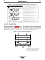
FIGURE A.5 - INPUT CONNECTION DIAGRAM FOR 230/460/575 VOL
TS AC, 60 HZ
D o n o t o p e r a t e w it h c o v e r s
re m o v e d
D is c o n n e c t in p u t p o w e r b e f o r e
s e r v ic in g
L IN E S
IN P U T
{
L3
W
L2
V
GND
O n ly q u a lif ie d p e r s o n s s h o u ld in s t a ll,
u s e o r s e r v ic e t h is e q u ip m e n t
C R 1
H4
R E C ONNE C T
15
5
PANE L
14
H2
H3
1
2
3
A T L E A S T 6 0 0 V IN S U L A T IO N .
8
7
3 . C O N N E C T T E R M IN A L M A R K E D
9
5 . T A P E S E P E R A T E L Y T O P R O V ID E A T L E A S T 6 0 0 V IN S U L A T IO N 1 , 2 , 3 , 7 , 8 , 9 .
TR ANSF.
L IN E S
IN P U T
{
L2
R E C ONNE C T
9
5
2
V
PANE L
8
1
U
H3
C O N N E C T IO N F O R 4 6 0 V O L T S , 6 0 H Z .
6
3
C ONTAC TOR
L1
GND
T A P E IN S U L A T E D U N U S E D L E A D S T O G E T H E R A W A Y F R O M L IV E M E T A L P A R T S .
C R 1
W
H2
H4
16 17 18
2 . IN S U L A T E U N U S E D H 2 , H 4 L E A D T E R M IN A L S S E P E R A T E L Y T O P R O V ID E
A T L E A S T 6 0 0 V IN S U L A T IO N .
3 . C O N N E C T T E R M IN A L M A R K E D
13 14 15
5 . T A P E S E P E R A T E L Y T O P R O V ID E A T L E A S T 6 0 0 V IN S U L A T IO N 1 3 , 1 4 , 1 5 , 1 6 , 1 7 , 1 8 .
TR ANSF.
L IN E S
IN P U T
{
L3
L2
GND
T A P E IN S U L A T E D U N U S E D L E A D S T O G E T H E R A W A Y F R O M L IV E M E T A L P A R T S .
C R 1
C O N N E C T IO N F O R 2 3 0 V O L T S , 6 0 H Z .
9
3
8
V
2
C ONTAC TOR
L1
T O S Y S T E M G R O U N D P E R N A T IO N A L E L E C T R IC C O D E S .
4. C ONNE C T TR ANS FOR ME R LE ADS 1, 2, 3, 4 & 7, 5 & 8, 6 & 9 TO R E C ONNE C T P ANE L.
P IL O T
W
1 . C O N N E C T L 1 , L 2 & L 3 IN P U T S U P P L Y L IN E S A N D H 1 & H 3 P IL O T
T R A N S F O R M E R L E A D S T O T H E IN P U T S ID E O F C R 1 C O N T A C T O R A S S H O W N .
4
7
H1
T O S Y S T E M G R O U N D P E R N A T IO N A L E L E C T R IC C O D E S .
4. C ONNE C T TR ANS FOR ME R LE ADS 16, 17, 18, 4 & 13, 5 & 14, 6 & 15 TO R E C ONNE C T P ANE L.
P IL O T
L3
1 . C O N N E C T L 1 , L 2 & L 3 IN P U T S U P P L Y L IN E S A N D H 1 & H 4 P IL O T
2 . IN S U L A T E U N U S E D H 2 , H 3 L E A D T E R M IN A L S S E P E R A T E L Y T O P R O V ID E
13
H1
.
T R A N S F O R M E R L E A D S T O T H E IN P U T S ID E O F C R 1 C O N T A C T O R A S S H O W N .
4
16
U
IM P O R T A N T : C H A N G E L IN K P O S IT IO N S A N D P IL O T T R A N S F O R M E R C O N N E C T IO N S
N O T E : M A C H IN E S A R E S H IP P E D F R O M F A C T O R Y C O N N E C T E D F O R 5 7 5 V
C O N N E C T IO N F O R 5 7 5 V O L T S , 6 0 H Z .
6
18
17
C ONTAC TOR
L1
I D E A L A R C (2 3 0 / 4 6 0 / 5 7 5 )
IN P U T S U P P L Y C O N N E C T IO N D IA G R A M
D o n o t t o u c h e le c t r ic a lly liv e p a r t s
7
U
6
5
R E C ONNE C T
PANE L
1 . C O N N E C T L 1 , L 2 & L 3 IN P U T S U P P L Y L IN E S A N D H 1 & H 2 P IL O T
T R A N S F O R M E R L E A D S T O T H E IN P U T S ID E O F C R 1 C O N T A C T O R A S S H O W N .
4
2 . IN S U L A T E U N U S E D H 3 , H 4 L E A D T E R M IN A L S S E P E R A T E L Y T O P R O V ID E
1
A T L E A S T 6 0 0 V IN S U L A T IO N .
H2
H3
H4
H1
16 17 18
3 . C O N N E C T T E R M IN A L M A R K E D
13 14 15
P IL O T
5 . T A P E S E P E R A T E L Y T O P R O V ID E A T L E A S T 6 0 0 V IN S U L A T IO N 1 3 , 1 4 , 1 5 , 1 6 , 1 7 , 1 8 .
TR ANSF.
T H E L IN C O L N E L E C T R IC C O ., C L E V E L A N D O H IO U .S .A .
T O S Y S T E M G R O U N D P E R N A T IO N A L E L E C T R IC C O D E S .
4. C ONNE C T TR ANS FOR ME R LE ADS 1 & 7, 2 & 8, 3 & 9, 4 & 5 & 6, TO R E C ONNE C T P ANE L.
T A P E IN S U L A T E D U N U S E D L E A D S T O G E T H E R A W A Y F R O M L IV E M E T A L P A R T S .
M 15666
5-26-95
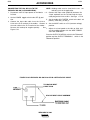
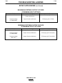
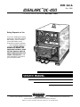
OUTPUT CONNECTIONS
The output (welding) cables are connected to the output
terminals marked Ò+Ó and Ò-Ó. See
able
T A.1 for recommended cable sizes for the combined lengths of electrode and work cables. They are located at the lower
right and lower left corners of the front panel. Strain
relief for the cables is provided by routing them through
the rectangular holes in the base before connecting
them to the output terminals. Lift the output terminal
cover to access the output terminals. Lower the cover
after making the connections. See Figure A.6.
FIGURE A.6 - OUTPUT TERMINAL CONNECTIONS
1. NEGATIVE (-) WELDING CABLE CONNECTION
2. POSITIVE (+) WELDING CABLE CONNECTION
3. CABLE STRAIN RELIEF HOLE LOCATION
IDEALARC DC-400
LINCOLN
ELECTRIC
¨
A-8
A-8
INSTALLATION
TABLE A.1 - CABLE SIZES FOR COMBINED LENGTHS OF COPPER ELECTRODE
AND WORK CABLES
Up to 50 ft
(15 m)
50 - 100 ft
(15 - 30 m)
100 - 150 ft
(30 - 46 m)
150 - 200 ft
(46 - 61 m)
200 - 250 ft
(67 - 76 m)
400 Amp
(100% Duty
Cycle)
3/0
85 mm2
3/0
85 mm2
3/0
85 mm2
3/0
85 mm2
4/0
107 mm2
500 Amp
(50% Duty
Cycle)
2/0
67 mm2
2/0
67 mm2
3/0
85 mm2
3/0
85 mm2
4/0
107 mm2
Machine Size
WIRE FEEDER CONNECTIONS
See the Accessories section of this manual for specific instructions on connecting the following semiautomatic and automatic wire feeders to the Idealarc
DC-400:
The work and electrode cables for stick, TIG, or
air/carbon arc cutting are connected as described earlier, under the heading Output Connections. A TIG
torch is connected to the electrode (+) terminal of the
welder. Select cable size according to Table A.1.
Automatic Wire Feeders:
WARNING
• NA-3
Do not connect a TIG torch and stick electrode cable
at the same time. They will both be electrically HOT.
• NA-5
Semi-automatic Wire Feeders:
If the Idealarc DC-400 is already set up for wire feeder
operation, all wire feeder unit control, electrode, and
work cables must be disconnected first before you
can connect the cables for stick, TIG, or air/carbon arc
operation.
• LN-7
• LN-8
• LN-9
However, the Idealarc DC-400 can be used for both
wire feeder operation and stick, TIG, air/carbon arc
operation if a K804-1 Multiprocess Switch is used.
See the Accessories section of this manual for specific instructions on connecting and using the
Multiprocess Switch.
• LN-25
• LN-742
CONNECTIONS FOR STICK, TIG, OR
AIR/CARBON ARC CUTTING OPERATIONS
WARNING
The output terminals are energized at all times when
the Idealarc DC-400 is used for stick, TIG, or air/carbon arc cutting.
96OCT
IDEALARC DC-400
LINCOLN
ELECTRIC
®
Section B-1
Section B-1
- OPERATION SECTION Operation...............................................................................................................................Section B
Safety Instructions ......................................................................................................................B-2
General Description ....................................................................................................................B-3
Recommended Processes ...................................................................................................B-3
Operational Features and Controls ......................................................................................B-3
Design Features and Advantages ........................................................................................B-3
Welding Capability................................................................................................................B-3
Limitations ............................................................................................................................B-3
Controls and Settings ................................................................................................................B-4
Welding Operation ......................................................................................................................B-6
Operating Steps ...................................................................................................................B-6
Local Control..................................................................................................................B-6
Remote Control ..............................................................................................................B-6
Welding Procedure Recommendations .........................................................................B-6
Semiautomatic and Automatic Wire Feeding with an Idealarc DC-400 ..............................B-6
NA-3 Automatic Wire Feeder .........................................................................................B-7
Good Arc Striking Guidelines for the NA-3.............................................................B-7
Arc Striking with the NA-3 Start Board ...................................................................B-7
NA-5 Automatic Wire Feeder .........................................................................................B-8
LN-8 Semiautomatic Wire Feeder..................................................................................B-8
LN-7 and LN-9 Semiautomatic Wire Feeders................................................................B-9
Overload Protection....................................................................................................................B-9
Auxiliary Power ...........................................................................................................................B-9
IDEALARC DC-400
LINCOLN
ELECTRIC
®
B-2
OPERATION
OPERATING INSTRUCTIONS
Read and understand this entire section of operating
instructions before operating the machine.
SAFETY INSTRUCTIONS
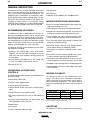
WARNING
ELECTRIC SHOCK can kill.
• Do not touch electrically live parts or
electrodes with your skin or wet clothing.
• Insulate yourself from the work and ground.
• Always wear dry insulating gloves.
FUMES AND GASES can be
dangerous.
• Keep your head out of fumes.
• Use ventilation or exhaust to remove
fumes from breathing zone.
WELDING SPARKS can cause
fire or explosion.
• Keep flammable material away.
• Do not weld on containers that have held combustibles.
ARC RAYS can burn.
• Wear eye, ear, and body protection.
Observe additional Safety Guidelines detailed in
the beginning of this manual.
IDEALARC DC-400
LINCOLN
ELECTRIC
®
B-2
B-3
B-3
OPERATION
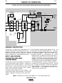
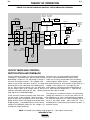
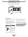
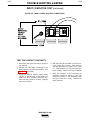
GENERAL DESCRIPTION
The Idealarc DC-400 is an SCR controlled three-phase
input, DC output power source for welding and cutting. It uses a single range potentiometer control. The
welderÕ
s unique combination of transformer, threephase semiconverter rectifier, capacitor bank, arc control choke, and solid state control system deliver outstanding arc characteristics in the constant voltage
mode. For stick welding, an Arc Force Control enables
the Idealarc-400 to perform much like the R3R-500.
¥ DC Ammeter
¥ DC Voltmeter
¥ Voltmeter Ò+Ó Electr
ode or Ò-Ó Electr
ode Switch
DESIGN FEATURES AND ADVANTAGES
¥ Input line voltage compensation keeps output constant for fluctuations of ± 10%.
¥ SCR control extends life of mechanical contactors.
RECOMMENDED PROCESSES
The Idealarc DC-400 is recomended for all open arc
processes including Innershield¨ and all solid wire and
gas procedures within its capacity of 60 to 500 amps.
It also can perform stick and TIG welding and air/carbon arc gouging up to 5/16Ó (8 mm) diameter. A mode
switch on the front control panel selects CV (FCAW,
GMAW), CV Submerged Arc, or CC (stick/TIG).
The Idealarc DC-400 can be connected to wire feeding equipment, including:
¥ Automatic wire feeders NA-3, NA-5, and NA-5R.
(Requires the DC-400 Diode Kit option to use the
cold start and cold electrode sensing features of
these feeders.)
¥ Semi-automatic wire feeders LN-7, LN-7 GMA, LN8, LN-9, LN-9 GMA, LN23P, LN-25, LN-742.
¥ Hinged front control panel provides easy access to
printed circuit boards and other control circuitry.
¥ Fully enclosed fan motor with permanently lubricated, sealed ball bearings needs no maintenance.
¥ Fully recessed control panel protects controls and
minimizes accidental contact.
¥ Recessed output terminals and hinged terminal
cover reduce chance of accidental contact.
¥ Low profile case permits installation under a workbench.
¥ Removable rear access panel provides easy access
to input contactor and input lead connections.
¥ Removable case sides provide easy access for service or inspection, even when machines are stacked.
¥ Dripproof enclosure design permits outdoor operation.
¥ Tractors LT-56, LT-7.
¥ Double-dipped transformer, SCR bridge, and choke
resist corrosion.
OPERATIONAL FEATURES AND
CONTROLS
The following operational controls are standard on the
Idealarc DC-400:
¥ Power Source Pilot Light
¥ ON/OFF Power Toggle Switch
¥ Output Control Potentiometer
WELDING CAPABILITY
The Idealarc DC-400 has the following duty cycle
ratings. If the duty cycle is exceeded, a thermal protector will shut off the machine output until it cools to
normal operating temperature. The amber thermal
protection indicator light will turn on until the machine
cools.
¥ Output Control Switch (with Local or Remote positions)
Duty Cycle*
100%
60%
50%
¥ Output Terminals On or Remote Switch
¥ Arc Force Selector (for CC stick or TIG processes
only)
¥ Auxiliary Power Connections for Wire Feeder and
Other Equipment (115V and 42V)
¥ Mode Switch
Amps
400
450
500
Volts
36
38
40
*Based on a 10 minute time period. For example, a 60% duty cycle
means 6 minutes on and 4 minutes off.
¥ Arc Control
LIMITATIONS
¥ Thermal Protection Indicator Light
The Idealarc DC-400 has no provisions for paralleling.
IDEALARC DC-400
LINCOLN
ELECTRIC
¨
B-4
OPERATION
B-4
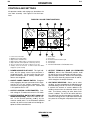
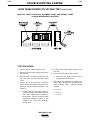
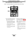
CONTROLS AND SETTINGS
All operator controls and settings are located on the
case front assembly. See Figure B.1 for their locations.
FIGURE B.1 Ð CASE FRONT CONTROLS
1.
2.
3.
4.
5.
6.
7.
Power Source Pilot Light
ON/OFF Power Toggle Switch
Output Control Potentiometer
Output Control Switch (with Local or Remote positions)
Output Terminals Switch (with On or Remote positions)
Arc Force Selector (for CC stick or TIG processes only)
Auxiliary Power Connections for Wire Feeder and Other
Equipment (115V and 42V)
1. POWER SOURCE PILOT LIGHT: This light indicates that the power source input contactor is
energized (closed). This also means that the main
power transformer and all auxiliary control transformers are energized.
2. ON/OFF POWER TOGGLE SWITCH: Energizes
or de-engergizes the input contactor which is powered by the 115 volt auxiliary transformer. The
switch turns the machine ON or OFF. Position ÒIÓ
is ON; position Ò0Ó is OFF
.
3. OUTPUT CONTROL POTENTIOMETER: Controls voltage in CV mode and current in CC mode.
4. OUTPUT CONTROL SWITCH (WITH LOCAL OR
REMOTE POSITIONS): Selects the mode of control. In the ÒLocalÓ position, contr
ol is by the
machine control panel. In the ÒRemoteÓ position,
control is by either a wire feeder unit or through an
optional remote control device.
8.
9.
10.
11.
12.
13.
Mode Switch
Arc Control
Thermal Protection Indicator Light
DC Ammeter
DC Voltmeter
Voltmeter Ò+Ó Electr
ode or Ò-Ó Electr
ode Switch
5. OUTPUT TERMINALS ÒONÓ OR ÒREMOTEÓ
SWITCH: When in the ÒRemoteÓ position, leads
#2 and #4 have to be jumpered externally to energize the output terminals. When in the ÒONÓ position, this switch internally jumpers leads #2 and #4,
which energizes the output terminals.
6. ARC FORCE SELECTOR: Allows you to select
the ideal arc force according to the procedure and
electrode being used for CC stick or TIG welding.
It controls the amount of current added to the
welding current when the electrode shorts to the
work. At minimum setting, no extra short circuit
current is added. The arc will be softer and have
less spatter but may be more prone to sticking. At
maximum setting, the arc will be more forceful and
less prone to sticking but will produce more spatter.
IDEALARC DC-400
LINCOLN
ELECTRIC
¨
B-5
OPERATION
7. AUXILIARY POWER AND REMOTE CONTROL
CONNECTIONS FOR WIRE FEEDER AND
OTHER EQUIPMENT (115V AND 42V): The 14pin amphenol receptacle provides either 115 or
42 volts AC as well as remote control connections. Terminal strips with screw connections are
located behind the hinged control panel for hard
wired control. Only 115 volts AC is available on
the terminal strip. A strain relief connector is provided for cable entry.
8. MODE SWITCH: Selects between Constant
Voltage FCAW/GMAW and Constant Voltage
Submerged Arc (Red range on dial), and Constant
Current Stick/TIG (Blue range on dial).
9. ARC CONTROL: A five-position switch that
changes the pinch effect of the arc when in the CV
FCAW/GMAW mode. It allows control of spatter,
fluidity, and bead shape. The Arc Control is set to
provide optimum welding depending on the
process, position, and electrode. Pinch effect is
increased by turning the control clockwise. It can
also be adjusted while the machine is in operation.
10. THERMAL PROTECTION INDICATOR LIGHT:
This amber light indicates that either of the two
protective thermostats has opened. Output
power is removed, but input power is still being
applied to the machine.
11. DC AMMETER:
welding.
Displays output current when
12. DC VOLTMETER: Displays output voltage when
welding.
13. VOLTMETER “+” ELECTRODE OR “-” ELECTRODE SWITCH: Selects the electrode polarity
for the remote work sensing lead (#21) when using
automatic or semiautomatic wire feeders.
IDEALARC DC-400
LINCOLN
ELECTRIC
®
B-5
B-6
OPERATION
B-6
WELDING OPERATION
REMOTE CONTROL
OPERATING STEPS
The toggle switch on the control panel labeled ÒOutput
Control RemoteÓ gives you the option of controlling
the machine output from a remote location. In the
ÒRemoteÓ position a wir
e feeder with remote control
capabilities or a remote control device such as a K775
must be connected to the DC-400. Refer to the
Accessories section for wire feeder installation information.
LOCAL CONTROL
The following procedures are for using the Idealarc
DC-400 in the local control mode of operation. For
remote control of the machine, see the REMOTE
CONTROL section.
Before operating the machine, make sure you have all
materials needed to complete the job. Be sure you are
familiar with and have taken all possible safety precautions before starting work. It is important that you
follow these operating steps each time you use the
machine.
1. Turn on the main AC input power to the machine.
2. Set the VOLTMETER Ò+Ó or Ò-Ó switch to the
appropriate position.
¥ Set toggle to Ò«Electr
ode NegativeÓ position if
the electrode is connected to the negative (-)
output terminal.
¥ Set toggle to ÒElectrode PositiveÓ position if the
electrode is connected to the positive (+) output
terminal.
3. Set the welding MODE switch to welding process
being used.
¥ CV FCAW/GMAW
¥ CV Submerged Arc
¥ CC Stick/Tig
4. Set the OUTPUT CONTROL switch to ÒLocal.Ó
(Exception: when using an LN-9, LN-9 GMA, or
NA-5 wire feeder, set the switch to ÒRemote.Ó
Otherwise, the wire feeder may automatically shut
down.
5. Set the OUTPUT TERMINALS switch to the
desired mode.
6. Set the ARC FORCE CONTROL to midrange, 5-6.
This control is for CC stick or TIG welding only.
Adjust for best characteristics as necessary.
7. Set the ARC CONTROL to midrange, 3. This control is for CV FCAW/GMAW welding only. Adjust
as necessary for best pinch control.
8. Set the ON/OFF POWER toggle switch to the ON
position (1).
¥ The power source pilot light glows.
WELDING PROCEDURE RECOMMENDATIONS
Select Mode Switch position based on type of welding
to be done.
1. FCAW/GMAW Welding/Other Open Arc Processes:
Use the CV FCAW/GMAW mode.
2. Submerged Arc Welding: Use the CV Submerged
Arc mode. If performing high speed welding,
switch between the CV Submerged Arc and the CV
FCAW/GMAW mode and use the mode that produces the best welding results.
3. Air/Carbon Arc Cutting / Stick Welding / High
Current, Large Puddle Submerged Arc Welding:
Use the CC mode. When the Idealarc DC-400 is
used for Air/Carbon Arc cutting, the OUTPUT
CONTROL potentiometer should be set to Ò9Ó initially. Based on the size of the carbon being used
or the process, turn the potentiometer to a lower
setting as required by the process. You can use
carbon rods up to 5/16Ó (8 mm) in diameter at currents as high as 450 amps with excellent arc control. The welder protection circuit protects the
machine from extremely high short circuiting
pulses.
SEMIAUTOMATIC AND AUTOMATIC WIRE
FEEDING WITHAN IDEALARC DC-400
When using the Idealarc DC-400 with semiautomatic
or automatic wire feeding equipment and for stick
welding or air/carbon arc cutting, it is recommended
that the optional MULTIPROCESS switch be used.
This switch permits you to easily change the polarity of
the connected wire feeding equipment or switch to
stick welding or air/carbon arc cutting.
¥ The fan starts.
9. Set OUTPUT CONTROL potentiometer to desired
voltage or current.
10. Make the weld.
IDEALARC DC-400
LINCOLN
ELECTRIC
¨
B-7
OPERATION
NOTE: The open circuit voltage of the Idealarc
DC-400 varies from apporximately 12
volts to 45 volts in the CV FCAW/GMAW
or CV Submerged Arc modes. The open
circuit voltage is constant in the CC mode.
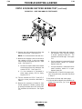
NA-3 AUTOMATIC WIRE FEEDER
1. Set the DC-400 OUTPUT CONTROL switch to
ÒRemote.Ó
NOTE: Later model NA-3 automatic wire feeders
are capable of cold starts when the NA-3
Mode switch is in the CV or CC mode position. Some earlier models are capable of
cold starting only in the CC mode position.
Cold starting enables you to inch the wire
down to the work, automatically stop, and
automatically energize the flux hopper
valve. The cold start feature requires the
factory installed diode option. See the
Accessories section.
3. Run a test weld. Set proper current, voltage, and
travel speed.
a. For the best starting performance, the NA-3
Open Circuit Voltage Control and Voltage
Control setting should be the same. Set the
Inch Speed Control for the slowest inch speed
possible.
b. To adjust the Open Circuit Voltage Control to
get the best starting performance, make
repeated starts observing the NA-3 voltmeter.
2. Set the DC-400 welding MODE switch for the
desired process: CV Submerged Arc, CV
FCAW/GMAW mode or CC mode.
When the voltmeter pointer swings smoothly up to
the desired arc voltage, without undershooting or
overshooting the desired arc voltage, the Open
Circuit Voltage Control is set properly.
3. Set the NA-3 mode switch position to either CV or
CC to match the DC-400 mode selected in step 2.
If the voltmeter pointer overshoots the desired
voltage and then returns to the desired voltage, the
Open Circuit Voltage Control is set too high. This
can result in a bad start where the wire tends to
Òblast off.Ó
4. Set the OUTPUT CONTROL switch to ÒRemote.Ó
5. Set the OUTPUT TERMINALS switch to ÒRemote.Ó
6. For CC welding, set the ARC FORCE CONTROL to
midrange, 5-6. After welding starts, adjust as necessary.
If the voltmeter pointer hesitates before coming up
to the desired voltage, the Open Circuit Voltage
Control is set too low. This can cause the electrode to stub.
7. For CV FCAW/GMAW welding, set the ARC CONTROL to midrange, 3. After welding starts, adjust
as necessary.
8. Refer to the NA-3 operatorÕ
s manual for instructions
on how to use the NA-3 in conjunction with the DC400.
4. Start and make the weld.
a. Cold starts. For cold starts, be sure the work
piece is clean and the electrode makes positive contact with the work piece.
9. Follow the guidelines for good arc striking detailed
below for each welding mode.
GOOD ARC STRIKING GUIDELINES FOR THE
NA-3 WITH THE IDEALARC DC-400 IN THE CV
FCAW/GMAW, CV SUBMERGED ARC OR
STICK/TIG CC WELDING MODES.
B-7
b. Hot ÒOn the FlyÓ starts. For hot starts, travel
should begin before the wire contacts the work
piece.
ARC STRIKING WITH THE NA-3 START BOARD
Following are some basic arc striking techniques that
apply to all wire feed processes. Using these procedures should provide trouble-free starting. These procedures apply to single, solid wires and Innershield
wires.
1. Cut the electrode to a sharp point.
2. Set the NA-3 Open Circuit Voltage Control to the
same dial setting as the Arc Voltage Control. If this
is a new welding procedure, a good starting point is
to set the Open Circuit Voltage Control to #6.
When electrical stickouts exceed 1-3/4Ó (44.4 mm) an
NA-3 Start Board may be required to improve arc striking.
When the NA-3 Start Board is used to improve arc
striking, use the following procedures:
1. Set start time at 0.
2. Set NA-3 start current and start voltage at midrange.
3. Set the NA-3 output current and voltage to the
proper settings for the welding procedure to be
used.
IDEALARC DC-400
LINCOLN
ELECTRIC
¨
B-8
OPERATION
B-8
4. Turn the Start Board Timer to maximum.
NA-5 AUTOMATIVE WIRE FEEDER
5. Set Start Board current and voltage control.
When using the Idealarc DC-400 with the NA-5 wire
feeder, set the controls on the Idealarc DC-400 as follows for the best performance:
a.
Set the Start Board current control to 1-1/2
dial numbers below that set on the NA-3 current control.
b. Set the Start Board voltage control equal with
the NA-3 voltage control setting.
NOTE: These Start Board current and voltage settings result in a start up current that is
lower than the NA-3 current setting and
approximately equal with the NA-3 voltage
setting for the desired welding procedure.
2. Connect the electrode cables to the terminal
polarity to be used.
3. Set the VOLTMETER Ò+Ó or Ò-Ó switch to the same
polarity as the electrode cable connection.
4. Set the OUTPUT CONTROL switch to ÒRemote.Ó
5. Set the OUTPUT TERMINALS switch to ÒRemote.Ó
6. Establish the correct arc striking procedure with
the NA-3 Start Board timer set at maximum.
a.
1. Turn OFF main AC input power to the Idealarc DC400.
For the best starting performance, the NA-3
Open Circuit Voltage Control and Voltage
Control setting should be the same. Set the
Inch Speed Control for the slowest inch speed
possible.
6. Set the Idealarc DC-400 welding MODE switch to
the position that matches the welding process
being used.
a. For submerged arc welding, set welding
MODE SWITCH TO CV SUBMERGED ARC
position.
b. To adjust the Open Circuit Voltage Control to
get the best starting performance, make
repeated starts observing the NA-3 voltmeter.
When the voltmeter pointer swings smoothly up to
the desired arc voltage, without undershooting or
overshooting the desired arc voltage, the Open
Circuit Voltage Control is set properly.
If the voltmeter pointer overshoots the desired
voltage and then returns to the desired voltage,
the Open Circuit Voltage Control is set too high.
This can result in a bad start where the wire tends
to Òblast of
f.Ó
If the voltmeter pointer hesitates before coming up
to the desired voltage, the Open Circuit Voltage
Control is set too low. This can cause the electrode to stub.
c. Set NA-3 Start Board current and voltage as
close to the welding procedure current and
voltage as possible.
b. For all open arc welding processes, set welding MODE switch TO CV FCAW/GMAW position.
7. Set the ARC CONTROL to midrange, 3.
welding starts, adjust as necessary.
After
LN-8 SEMIAUTOMATIC WIRE FEEDER
To use the LN-8 Semiautomatic Wire Feeder with the
Idealarc DC-400:
1. Set the Idealarc DC-400 welding MODE switch to
either CV FCAW/GMAW mode or CV Submerged
Arc mode, depending on the welding process
being used.
2. Set the Idealarc DC-400 OUTPUT CONTROL
switch to ÒRemote.Ó
3. Set the OUTPUT TERMINALS switch to ÒRemote.Ó
4. Set the ARC CONTROL to midrange, 3.
NOTE: The Start Board current and voltage
should be as close as possible to the
welding procedure current and voltage,
while still getting satisfactory starts.
d. Set the start time to as low a time as possible
while still getting satisfactory starts.
5. Set the LN-8 Welding Mode switch to the CV position. The LN-8 Welding Mode switch is located on
the variable voltage (CC) board.
6. Refer to the LN-8 OperatorÕ
s Manual for instructions on how to use the LN-8.
7. Start and make the weld.
IDEALARC DC-400
LINCOLN
ELECTRIC
¨
B-9
OPERATION
LN-7 AND LN-9 SEMIAUTOMATIC WIRE FEEDERS
OR OTHER CONSTANT SPEED WIRE FEEDERS
To use the LN-7, LN-9, or other constant wire feed
speed semiautomatic wire feeders with the Idealarc
DC-400:
1. Set the Idealarc DC-400 welding MODE switch to
either CV FCAW/GMAW mode or CV Submerged
Arc mode, depending on the welding process
being used.
NOTE: These semiautomatic wire feeders cannot
be used in the CC mode.
2. Set the Idealarc DC-400 OUTPUT CONTROL
switch.
a. LN-7: Use either an optional K775 Remote
Control Box Assembly or set the Idealarc DC400 OUTPUT CONTROL switch in the “Local”
position.
b. LN-9: Refer to the LN-9 Operator’s Manual for
instructions on how to use the LN-9.
B-9
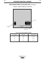
OVERLOAD PROTECTION
The power source is thermostatically protected with
proximity thermostats against overloads or insufficient
cooling. One thermostat is located on the nose of the
center bottom primary coil. A second thermostat is
attached to the lead connecting the secondaries. If the
machine is overloaded, the primary thermostat opens,
the output becomes zero, and the amber thermal protection light comes on. The fan will continue to run.
The secondary thermostat opens with either an excessive overload or insufficient cooling. The output
becomes zero, and the amber thermal protection light
comes on. When the machine cools, the thermostats
reset, and the thermal protection light goes off.
The power source is also protected against overloads
on the SCR bridge asssembly through an electronic
protection circuit. This circuit senses an overload on
the power source and limits the output to 550 amps by
phasing back the SCRs.
c. LN-25: Refer to the LN-25 Operator’s Manual
for instructions on how to use the LN-25.
The Idealarc DC-400 also has self-restoring fusing to
prevent damage to the machine in the event of an
accidental grounding of the remote control leads (#75,
#76 or #77).
d. LN-742: Refer to the LN-742 Operator’s
Manual for instructions on how to use the LN742.
AUXILIARY POWER
The Idealarc DC-400 can provide nominally 115 volt
AC and 42 volt AC auxiliary power for operating wire
feeding equipment and other accessories. This power
is available at the 14-pin amphenol on the control
panel and/or at the terminal strip behind the hinged
control panel on the case front. On the amphenol, 115
volts AC is available at pins A and J (Domestic and
Export models only); 42 volts AC is available at pins I
and K. On the terminal strip, 115 volts AC is available
at terminals 31 and 32; 42 volts AC is not available.
The two circuits, 115 volts AC and 42 volts AC, are isolated; and each is protected by a 10 amp circuit breaker.
On European and export models, a Continental
European receptacle is provided on the rear panel for
supplying 220 volts AC to a water cooler. A 2 amp circuit breaker, also located on the rear panel, protects
this circuit from overloads or short circuits.
IDEALARC DC-400
LINCOLN
ELECTRIC
®
Section C-1
Section C-1
TABLE OF CONTENTS
- ACCESSORIES Accessories...........................................................................................................................Section C
Options/Accessories...................................................................................................................C-2
Factory Installed Option.......................................................................................................C-2
Field Installed Options .........................................................................................................C-2
Cover for 14-Pin Amphenol ...........................................................................................C-2
Multiprocess Switch (K804-1)........................................................................................C-2
Remote Output Adapter Cable (K857)...........................................................................C-4
Remote Control Adapter Cable (K864) ..........................................................................C-4
Amptrol Adapter Cable (K843) .......................................................................................C-4
Capacitor Discharge Circuit (K828-1) ............................................................................C-6
Hi-Freq Kit (K799) ..........................................................................................................C-6
Amptrol Adapter for K799 (K915) ..................................................................................C-6
Undercarriages (K817, K817R, K841) ............................................................................C-6
Connection of Lincoln Electric Automatic or Semiautomatic Wire Feeders ..............................C-6
Automatic Wire Feeders.......................................................................................................C-6
NA-3 (Terminal Strip) ......................................................................................................C-6
NA-5 (Terminal Strip) ......................................................................................................C-7
NA-3 or NA-5 (14-Pin Amphenol) ..................................................................................C-8
Semiautomatic Wire Feeders ...............................................................................................C-9
LN-7 (14-Pin Amphenol) ................................................................................................C-9
LN-7 (Terminal Strip) ....................................................................................................C-10
LN-8 or LN-9 (Terminal Strip).......................................................................................C-11
LN-8 or LN-9 (14-Pin Amphenol) .................................................................................C-12
LN-742 (14-Pin Amphenol) ..........................................................................................C-13
IDEALARC DC-400
LINCOLN
ELECTRIC
®
C-2
ACCESSORIES
C-2
OPTIONS/ACCESSORIES
The Multiprocess Switch gives you the ability to:
FACTORY INSTALLED OPTION
¥ Switch between ÒStick Welding/Air-Carbon Arc
CuttingÓ or ÒPositive Wir
e FeederÓ or ÒNegative Wir
e
Feeder.Ó
DIODE OPTION
This factory installed option allows use of the coldstart and cold electrode sensing features of the NA-3,
NA-5, or NA-5R automatic wire feeders. See the topic,
Connecting the NA-3 [NA-5] to the Idealarc DC-400
in this section of the manual.
FIELD INSTALLED OPTIONS
The following options/accessories are available for
your Idealarc DC-400 from your local Lincoln
Distributor.
¥ Change the polarity of a semi-automatic or automatic wire feeder without changing any electrical
cable connections. See Figure C.1.
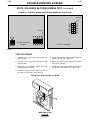
The Multiprocess Switch has two sets of output terminals. You connect the wire feeder unit cables to the
set of terminals on the left side of the box (facing the
front of the machine) and the stick or air/carbon arc
cables to the set of terminals on the right side as
shown in Figure C.1.
COVER FOR 14-PIN AMPHENOL (LINCOLN
ELECTRIC PART NUMBER S17062-3)
When the Multiprocess Switch is in the ÒStick Welding/
Air-Carbon ArcÓ position, only those terminals are
energized. The wire feeder nozzle or gun and electrode are not electrically ÒhotÓ when in this mode.
Protects the amphenol from dirt and moisture when
the amphenol is not being used.
Refer to installation instructions (M17137) included
with Multiprocess Kit for installation.
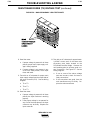
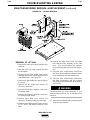
MULTIPROCESS SWITCH (K804-1. ALSO
AVAILABLE AS A FACTORY INSTALLED OPTION.)
Required when using the DC-400 for both automatic/semiautomatic and stick/air carbon arc. This field or
factory installed kit mounts on the front of the DC-400.
It includes hinged covers over its output studs.
The switch has three positions.
¥ Wire Feeder Positive
¥ Wire Feeder Negative
¥ Stick/Air Carbon Arc
FIGURE C.1
MULTIPROCESS SWITCH
IDEALARC DC-400
LINCOLN
ELECTRIC
¨
C-3
C-3
ACCESSORIES
Multiprocess Switch Operation
The operation of the Multiprocess Switch is as follows:
A semiautomatic or automatic wire feed unit electrode
and work cables are connected to the terminals on the
left side of the box. Stick or air carbon arc electrode
and work cables are connected to the terminals on the
switch. With the switch in the left position, the wire
feed terminals are electrode negative. In the center
position, the wire feeder terminals are electrode positive. In both the left and center switch position, the
right side stick terminals are disconnected. In the right
switch position, the wire feed terminals are disconnected from the DC-400 and the stick terminals connected. The polarity of the stick terminals is marked
on the end of the box. To change polarity, the electrode and work cables must be interchanged. In the
stick position, the stick terminals are energized at all
times.
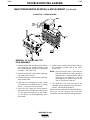
Connections
If both stick and semiautomatic welding is done on the
same workpiece, only one work cable is required. To
do this, connect a 4/0 (107 mm2) jumper from the work
terminal on the semiautomatic side to the terminal to
be used for work on the stick side. The work cable
from the semiautomatic side then serves as the work
cable for both semiautomatic and stick welding. See
Figure C.2.
To change stick polarity, reverse the leads at the (+)
and (-) terminals on the right side of the Multiprocess
Switch.
NOTE: When a DC-400 equipped with Multiprocess
Switch is mounted on an undercarriage, the
undercarriage handle in the resting position
can hit the case of the Multiprocess Switch.
This does no harm, but if the user desires, a
1/4” or 3/8” bolt and nut may be placed in the
hole in the undercarriage tow bar to limit the
travel of the undercarriage handle.
(For those applications where it is not necessary to
have separate work cables for stick and semiautomatic welding.)
FIGURE C.2 – SINGLE WORK CABLE WITH JUMPER
To stick electrode holder or
air carbon arc torch
To semi-auto or auto equipment
User supplied 4/0 (107 mm2)
jumper
IDEALARC DC-400
LINCOLN
ELECTRIC
®
C-4
C-4
ACCESSORIES
K843 AMPTROLª ADAPTER INSTALLATION
INSTRUCTIONS
REMOTE OUTPUT CONTROL (K857 WITH K864
ADAPTER PLUG OR K775)
The K857 has a 6-pin MS-style connector . The K857
requir es a K864 adapter cable which connects to the
14-pin connector on the machine.
WARNING
ELECTRIC SHOCK can kill.
An optional Òr emote output contr olÓ is available. This
is the same r emote contr ol that is used on the Lincoln
¥ Tur n the input supply power OFF
R3R and DC-600 power sour ces (K775). The K775
befor e installing plugs or cables or
consists of a contr ol box with 28 ft (8.5m) of four conwhen connecting or disconnecting
ductor cable. This connects to terminals 75, 76, and
plugs to the welder .
77 on the terminal strip and the case gr ounding scr ew
marked with the symbol
on the machine. These
terminals ar e located behind the contr ol panel on the This K843 adapter is used to connect Amptr ol (K812,
front. This device will give the same contr ol as the out- K813 or K870), r emote contr ol (K775), and Hi-Fr eqª
put contr ol on the machine.
(K799) accessories to the DC-400. The OUTPUT
CONTROL switch must be in ÒRemoteÓ for Amptr olª
REMOTE CONTROL ADAPTER CABLE (K864)
to contr ol curr ent. Accessories may be combined and
A ÒVÓ cable 12 inches (.30 m) long to connect a K857 connected in four dif ferent ways, as shown on the folRemote Contr ol, K812 Hand Amptr ol or K870 Foot lowing page.
Amptr ol (6-pin connector) with a wir e-feeder (14-pin
connector) and the machine (14-pin connector). If a
remote contr ol or amptr ol is used alone, the wir e-feeder connection is not used. See Figur e C.3.
AMPTROLª ADAPTER CABLE (K843)
A five wir e cable, 12 inches (.30 m) long, is available for
easy connection of standar d K812 Hand Amptr ol or
K870 Foot Amptr ol. The cable has a 6-pin MS-style
connector which connects to the Amptr ol, and terminals which connect to 75, 76 and 77 on the machine
terminal strip and to the case gr ounding scr ew. The
Amptr ol will contr ol the same range of output as the
curr ent contr ol on the welder . (If a smaller range of
contr ol is desir ed for finer adjustment, a K775 Remote
may be used in conjunction with the Amptr ol Adapter
Cable Kit. Connection information is included with the
Amptr ol Adapter Cable Kit.) The Amptr ol ar c start
switch does not function in this application.
FIGURE C.3 Ð REMOTE CONTROL ADAPTER CABLE (K864)
CABLE RECEPTACLE (6 SOCKET)
TO: 1) K857 REMOTE CONTROL
2) K812 HAND AMPTROL
3) K870 FOOT AMPTROL
STRAIGHT PLUG (14 PIN)
TO POWER SOURCE
CABLE RECEPTACLE (14 SOCKET)
TO: L-7 WIRE FEEDER
IDEALARC DC-400
LINCOLN
ELECTRIC
¨
C-5
C-5
ACCESSORIES
K843 AMPTROL ADAPTER INSTALLATION INSTRUCTIONS (Continued)
Amptrol Only: The Amptrol provides remote current
control through the full range of the power source.
Amptrol and Hi-Freq. Kit: The Amptrol will start the
Hi-Freq kit to turn on gas and high frequency starting
for DC TIG welding. The Amptrol controls current
through the full range of the power source.
K812, K813 or
K870 Amptrol
K812, K813
or K870
Amptrol
K799
Hi-Freq Kit
K843
Adapter
Power source
terminal
strip
Arc start cable
(included with
K799)
K843 Adapter
CUT OFF
ARC START
SWITCH and connect black
lead to black and white
lead to white.
Black and white leads
not used. Tape
and insulate.
Amptrol Plus Remote Limit Contr
ol:
The Amptrol
provides remote current control from the minimum of
the power source to a maximum set by the remote
limit control.
Amptrol and Hi-Freq. Kit Plus Remote Limit
Control: The Amptrol switch will start the Hi-Freq kit to
turn on gas and high frequency starting for DC TIG
welding. The Amptrol controls current from the minimum of the power source to a maximum set by the
remote limit control.
K812, K813 or
K870 Amptrol
K799
Hi-Freq
Kit
K843
Adapter
Bolt and nut
connection.
Insulate
and tape.
Arc start cable
(included
with K799)
CUT OFF
ARC START
SWITCH and
connect black
lead to black and
white lead to white.
Black and white
leads not used.
Tape and insulate.
IDEALARC DC-400
LINCOLN
ELECTRIC
¨
K775 Remote
Limit Control
K812, K813
or K870
Amptrol
K843 Adapter
Bolt and nut
connection.
Insulate
and tape.
C-6
C-6
ACCESSORIES
CAPACITOR DISCHARGE CIRCUIT (K828-1)
Mounts inside the DC-400. Recommended when:
¥ DC-400 is used in conjunction with any LN-23P or
older LN-8 or LN-9 semiautomatic wire-feeder.
Eliminates possible arc flash re-start of weld when
trigger interlock is used. Not required with current
LN-8 (above Code 8700), or LN-9s with serial numbers above 115187 (manufactured after 12/83), or
any LN-9 having an L6043-1 Power PC Board.
¥ DC-400 is used with an LN-22 equipped with an
older K279 Contactor-Voltage Control Option.
Eliminates electrode overrun when gun trigger is
released. Not required when later K279 (above
Code 8800) is used.
¥ DC-400 is used with any semiautomatic wire-feeder
and possible small spark is objectionable if electrode touches work just after gun trigger is released.
Install per M17060 instructions included with the kit.
HI-FREQª KIT (K799 FOR CODES 8634 AND
ABOVE ONLY)
Kit supplies the high frequency plus gas valve for DC
TIG welding. The DC-400 is shipped with proper R.F.
bypass circuitry installed to protect the control circuit
when welding with a HI-FREQ unit. K844 Water Valve
Option Kit can be used with K799 when TIG welding
with water cooled torches.
AMPTROL ADAPTER FOR K799 HI-FREQ KIT
(K915. REQUIRES K864 ADAPTER OR K843
ADAPTER)
A ÒVÓ cable to connect a K799 Hi-Fr
eq kit (5-pin connector) with either a K812 Hand Amptrol or a K870
Foot Amptrol (6-pin connector) and the machine. The
cable going to the machine has a 6-pin connector
which requires either a K864 adapter to connect with
the 14-pin connector on the machine or a K843
adapter to connect to terminals #75, #76, #77 and the
case grounding screw on the machine.
UNDERCARRIAGES (K817, K817R, K841)
For easy moving of the machine, optional undercarriages are available with either steel (K817) or rubber
tired (K817R) wheels or a platform undercarriage
(K841) with mountings for two gas cylinders at the rear
of the welder.
CONNECTION OF LINCOLN ELECTRIC
AUTOMATIC OR SEMIAUTOMATIC WIRE
FEEDERS
WARNING
ELECTRIC SHOCK can kill.
¥ Only qualified personnel should
perform this maintenance.
¥ Turn the input power OFF at the disconnect switch or fuse box before working on this
equipment.
¥ Do not touch electrically hot parts.
Auxiliary power for wire feeder operation is available at
both a 14-pin amphenol and at terminal strips with
screw-type connections located behind the hinged
control panel on the front of the machine. The 14-pin
amphenol can provide both 115 VAC (pins A and J)
and 40-42 VAC (pins I and K). The terminal strip provides 115 VAC only (terminals 31 and 32). The two circuits are isolated, and each is protected by a 10A circuit breaker.
The following descriptions show how to connect the
wire feeders using either the 14-pin amphenol or the
terminal strip.
NOTE: The LN-742 wire feeder, because it operates
on 42 VAC, can be connected only to the 14pin amphenol.
AUTOMATIC WIRE FEEDERS
CONNECTING THE NA-3 TO THE IDEALARC
DC-400 (TERMINALSTRIP)
1. Disconnect main AC input power to the Idealarc
DC-400.
2. Set Idealarc DC-400 POWER toggle switch to the
OFF (0) position.
3. Connect the wire feeder control cable leads to the
Idealarc DC-400 terminal strip as shown in Figure
C.4.
Connect the wire feeder control cable ground lead
to the frame terminal marked
.
Installation instructions are included with each kit.
NOTE: The Idealarc DC-400 must be properly
grounded.
IDEALARC DC-400
LINCOLN
ELECTRIC
¨
C-7
ACCESSORIES
C-7
CONNECTING THE NA-5 TO THE
IDEALARC DC-400 (TERMINALSTRIP)
FIGURE C.4 Ð NA-3 WIRE FEEDER
CONNECTION TO THE IDEALARC DC-400
1. Disconnect main AC input power to the Idealar
DC-400.
c
2. Set the Idealar c DC-400 POWER toggle switch to
the OFF (0) position.
3. Connect the wir e feeder contr ol cable leads to the
Idealar c DC-400 terminal strip as shown in Figur e
C.5.
FIGURE C.5 Ð NA-5 WIRE FEEDER
CONNECTION TO THE IDEALARC DC-400
5. Extend wir e feeder contr ol cable lead #21 so it can
be connected dir ectly to the work piece.
a.
Make a bolted connection using A WG #14 or
lar ger insulated wir e. Tape the bolted connection with insulating tape.
b. An S-16586- X r emote voltage sensing work
lead is available for this purpose.
c.
Keep the #21 lead electrically separate fr
the work cable cir cuit and connection.
om
d. Tape the #21 lead to work cable for ease of
use.
NOTE: If using a K215 contr ol cable, connect
contr ol cable leads #75, #76, and #77 to
the matching #75, #76, and #77 terminals
on the terminal strip of the Idealar c DC400.
NOTE: The connection diagram shown in Figur e C.4
shows the electr ode connected for positive
polarity . To change polarity:
a. Set the Idealar c DC-400 POWER toggle
switch to the OFF (0) position.
b. Move the electr ode cable to the negative (-)
output terminal.
c.
4. Connect the wir e feeder contr ol cable gr ound lead
to the frame terminal marked
.
NOTE: The Idealar c DC-400 must be pr operly
grounded.
Move the work cable to the positive (+) output
terminal.
d. Set the VOL TMETER toggle switch to negative (-).
6. Set the DC-400 OUTPUT CONTROL switch to the
ÒRemoteÓ position and the OUTPUT TERMINALS
switch in the ÒRemoteÓ position.
IDEALARC DC-400
LINCOLN
ELECTRIC
¨
C-8
ACCESSORIES
5. Extend wire feeder control cable lead #21 so it can
be connected directly to the work piece.
a.
Make a bolted connection using AWG #14 or
larger insulated wire. Tape the bolted connection with insulating tape.
b. An S-16586- X remote voltage sensing work
lead is available for this purpose.
c. Keep the #21 lead electrically separate from
the work cable circuit and connection.
d. Tape the #21 lead to work cable for ease of
use.
6. Connect NA-5 wire feeder control jumpers on
Voltage Control Board. See NA-5 OperatorÕ
s
Manual.
NOTE: The connection diagram shown in Figure C.5
shows the electrode connected for positive
polarity. To change polarity:
NOTE: For proper NA-5 operation, the electrode
cables must be secured under the clamp bar
on the left side of the NA-5 Control Box.
7. Set the DC-400 OUTPUT CONTROL switch to the
ÒRemoteÓ position and the OUTPUT
TERMINALS
switch to the ÒRemoteÓ position.
CONNECTING THE NA-3 OR NA-5 TO THE
IDEALARC DC-400 (14-PIN AMPHENOL)
1. Disconnect main AC input power to the Idealarc
DC-400.
2. Set the Idealarc DC-400 POWER switch to the OFF
(0) position.
3. Connect the electrode cable from the K597-XX
Input Cable Assembly to the Ò+Ó terminal of the
welder and to the wire feeder. Connect the work
cable to the Ò-Ó terminal of the welder
. Reverse this
hookup for negative polarity. See Figure C.6.
NOTE: Welding cable must be sized for the current and duty cycle of the application.
a. Set the Idealarc DC-400 POWER toggle
switch to the OFF (0) position.
b. Move the electrode cable to the negative (-)
output terminal.
c. Move the work cable to the positive (+) output
terminal.
d. Set the VOLTMETER toggle switch to negative
(-).
C-8
4. Set the welder VOLTMETER switch to the desired
polarity, either DC (-) or DC (+).
5. Set the MODE switch to a CV (constant voltage)
position.
6. Set the DC-400 OUTPUT CONTROL switch to the
ÒRemoteÓ position and the OUTPUT
TERMINALS
switch to the ÒRemoteÓ position.
FIGURE C.6
IDEALARC DC-400/NA-3/NA-5 14-PIN AMPHENOL CONNECTION
TO NA-3 or NA-5 INPUT
CABLE PLUG
K597-XX INPUT CABLE ASSEMBLY
IDEALARC DC-400
LINCOLN
ELECTRIC
¨
C-9
ACCESSORIES
C-9
FIGURE C.7
IDEALARC DC-400/LN-7 WITH K584 INPUT CABLE ASSEMBLY CONNECTION DIAGRAM
SEMIAUTOMATIC WIRE FEEDERS
CONNECTING THE LN-7 TO THE IDEALARC
DC-400 (14-PIN AMPHENOL)
4. Connect K584-XX Input Cable between the DC400 and the LN-7. See Figure C.7.
1. Disconnect main AC input power to the Idealarc
DC-400.
5. Set the welder VOLTMETER toggle switch to the
desired polarity, either DC (-) or DC (+).
2. Set the POWER toggle switch to the OFF (0) position.
6. Set the MODE switch to a CV (constant voltage)
position at the welder.
3. Connect the electrode cable from the K584-XX
Input Cable Assembly to the “+” terminal of the
welder and to the LN-7 wire feeder. Connect the
work cable to the “-” terminal of the welder.
Reverse this hookup for negative polarity.
7. Adjust wire feed speed at the LN-7 and set the
welding voltage with the OUTPUT CONTROL.
NOTE: If optional remote control is used, place the
OUTPUT CONTROL and the OUTPUT TERMINALS switch in the “Remote” position.
NOTE: Welding cable must be sized for the current
and duty cycle of the application.
IDEALARC DC-400
LINCOLN
ELECTRIC
®
C-10
ACCESSORIES
C-10
FIGURE C.8 - LN-7 WIRE FEEDER CONNECTION TO THE IDEALARC DC-400
CONNECTING THE LN-7 TO THE
IDEALARC DC-400 (TERMINAL STRIP)
1. Disconnect main AC input power to the Idealar
DC-400.
NOTE: If the work cable length is less than 25 feet
and the connections to the work piece ar e
secur e, then wir e feeder contr ol cable lead
#21 can be connected dir ectly to the DC400 terminal strip.
c
2. Set the Idealar c DC-400 POWER toggle switch to
the OFF (0) position.
b. An S-16586- X r emote voltage sensing work
lead is available for this purpose.
3. Connect the wir e feeder contr ol cable leads to the
Idealar c DC-400 terminal strip as shown in Figur e
C.8.
c.
Keep the #21 lead electrically separate fr
the work cable cir cuit and connection.
om
d. Tape the #21 lead to work cable for ease of
use.
4. Connect the wir e feeder contr ol cable gr ound lead
to the frame terminal marked
.
NOTE: The Idealar c DC-400 must be pr operly
grounded.
NOTE: The connection diagram shown in Figur e
C.8 shows the electr ode connected for
positive polarity . To change polarity:
5. PERFORM THIS STEP ONL Y IF THE LN-7 IS
EQUIPPED WITH A METER KIT .
a.
Extend wir e feeder contr ol cable lead #21 so it can
be connected dir ectly to the work piece.
a.
Set the IDEALARC DC-400 POWER
switch to the OFF (0) position.
toggle
b. Move the electr ode cable to the negative (-)
output terminal.
Make a bolted connection using A WG #14 or
lar ger insulated wir e. Tape the bolted connection with insulating tape.
c.
Move the work cable to the positive (+) output
terminal.
d. Set the VOL TMETER toggle switch to negative (-).
IDEALARC DC-400
LINCOLN
ELECTRIC
¨
C-11
ACCESSORIES
C-11
FIGURE C.9 - LN-8 OR LN-9 WIRE FEEDER CONNECTION TO THE IDEALARC DC-400
NOTE: Using the extended #21 lead eliminates
the need to use the LN-9Õs remote work
lead accessory , which has a dir ect work
lead jack.
CONNECTING THE LN-8 OR LN-9 TO THE
IDEALARC DC-400 (TERMINAL STRIP)
1. Disconnect main AC input power to the Idealar
DC-400.
c
2. Set the Idealar c DC-400 POWER toggle switch to
the OFF (0) position.
6. Connect LN-9 wir e feeder contr ol jumpers on
Voltage Contr ol boar d. See LN-9 OperatorÕs
Manual.
3. Connect the wir e feeder contr ol cable leads to the
NOTE: The connection diagram shown in Figur e C.9
Idealar c DC-400 terminal strip as shown in Figur e
shows the electr ode connected for positive
C.9.
polarity . To change polarity:
4. Connect the wir e feeder contr ol cable gr ound lead
a. Set the Idealar c DC-400 POWER toggle
to the frame terminal marked
.
switch to the OFF (0) position.
5. Extend wir e feeder contr ol cable lead #21 so it can
b. Move the electr ode cable to the negative (-)
be connected dir ectly to the work piece.
output terminal.
a. Make a bolted connection using A WG #14 or
c. Move the work cable to the positive (+) output
lar ger insulated wir e. Tape the bolted connecterminal.
tion with insulating tape.
d. Set the VOL TMETER toggle switch to negative
b. An S-16586- X r emote voltage sensing work
(-).
lead is available for this purpose.
7. Set the OUTPUT CONTROL switch to the
c. Keep the #21 lead electrically separate fr om
ÒRemoteÓ position and the OUTPUT TERMINALS
the work cable cir cuit and connection.
switch to the ÒRemoteÓ position.
d. Tape the #21 lead to work cable for ease of
use.
IDEALARC DC-400
LINCOLN
ELECTRIC
¨
C-12
ACCESSORIES
C-12
NOTE: Welding cable must be sized for the curr
and duty cycle of the application.
CONNECTING THE LN-8 OR LN-9 TO THE
IDEALARC DC-400 (14-PIN AMPHENOL)
1. Disconnect main AC input power to the Idealar
DC-400.
2. Set the POWER toggle switch to the OFF (0) position.
ent
c 4. Connect the input cable (K595-XX) between the
14-pin amphenol on the DC-400 and the input
cable plug on the LN-8 or LN-9. See Figur e C.10.
5. Set the welder VOL TMETER switch to the desir ed
polarity , either DC (-) or DC (+).
3. Connect the electr ode cable fr om the LN-8 or
LN-9 to the Ò+Ó terminal of the welder . Connect 6. Set the MODE switch to a CV (constant voltage)
position.
the work cable to the Ò-Ó terminal of the welder .
Reverse this hookup for negative polarity . See
7. Adjust wir e feed speed at the LN-8 or LN-9 and
Figur e C.10.
set the welding voltage with the WIRE FEEDER
VOLTAGE CONTROL.
Place the OUTPUT CONTROL switch in the ÒRemoteÓ
position and the OUTPUT TERMINALS switch in the
ÒRemoteÓ position.
FIGURE C.10 Ð IDEALARC DC-400/LN-8 OR LN-9 WITH K595-XX CABLE
TO LN8/LN9 INPUT
CABLE PLUG
K595-XX INPUT CABLE ASSEMBLY
IDEALARC DC-400
LINCOLN
ELECTRIC
¨
C-13
ACCESSORIES
C-13
CONNECTING THE LN-742 TO THE
IDEALARC DC-400 (14-PIN AMPHENOL)
1. Disconnect main AC input power to the Idealar
DC-400.
c 5. Set the welder VOL TMETER switch to the desir ed
polarity , either DC (-) or DC (+).
2. Set the POWER toggle switch to the OFF (0) position.
6. Set the MODE switch to a CV (constant voltage)
position.
3. Connect the electr ode cable fr om the LN-742 to 7. Adjust wir e feed speed at the LN-742 and set the
the Ò+Ó terminal of the welder . Connect the work
welding voltage with the output ARC CONTROL to
cable to the Ò-Ó terminal of the welder . Reverse
a CV (constant voltage) position at the welder .
this hookup for negative polarity . See Figur e C.11.
NOTE: If optional r emote contr ol is used, set the
NOTE: Welding cable must be sized for the curr ent
OUTPUT CONTROL switch to the ÒRemoteÓ
and duty cycle of the application.
position and the OUTPUT TERMINALS switch
to the ÒRemoteÓ position.
4. Connect the K592 Contr ol Cable to the 14-pin
amphenol on the IDEALARC DC-400 and to the
input cable plug on the LN-742. See Figur e C.11.
FIGURE C.11 Ð IDEALARC DC-400/LN-742 CONNECTION DIAGRAM
IDEALARC DC-400
LINCOLN
ELECTRIC
¨
Section D-1
Section D-1
TABLE OF CONTENTS
-MAINTENANCEMaintenance .........................................................................................................................Section D
Safety Precautions......................................................................................................................D-2
Routine and Periodic Maintenance ............................................................................................D-2
General Component Locations...................................................................................................D-3
IDEALARC DC-400
LINCOLN
ELECTRIC
®
D-2
MAINTENANCE
D-2
SAFETY PRECAUTIONS
Perform periodically:
WARNING
ELECTRIC SHOCK can kill.
¥ Only
qualified
personnel
should perform this maintenance.
¥ Tur n the input power OFF at
the disconnect switch or fuse
box befor e working on this
equipment.
¥ Do not touch electrically hot parts.
1. In extr emely dusty conditions, dirt may clog the
cooling air channels, causing the machine to run
hot. Blow out the machine at r egular intervals with
low pr essur e air. Clean the following parts. See
Figur e D.1.
¥ Main transformer and choke
¥ SCR/diode bridge
¥ Contr ol PC boar d
¥ Starting PC boar d
¥ Electr ode and work cable connections
¥ Fan assembly
ROUTINE AND PERIODIC
MAINTENANCE
NOTE: The fan motor has sealed bearings that r
no service.
equir e
Perform the following pr eventative maintenance at ¥ Remote contr ol terminal strip TS1.
least once every six months.
NOTE: Keeping r emote contr ol terminal strip TS1
clean is especially important in damp locations.
Perform the following daily:
1. Check that no combustible materials ar e ar ound
the machine or in the welding or cutting ar ea.
2. Remove any debris, dust, dirt, or materials that
could block cooling air flow to the machine.
3. Inspect the electr ode cables for any slits or punctur es in the cable jacket. Also check for any other
condition that could af fect the pr oper operation of
the machine.
IDEALARC DC-400
LINCOLN
ELECTRIC
¨
D-3
D-3
MAINTENANCE
FIGURE D.1 – GENERAL COMPONENT LOCATIONS
1.
2.
3.
4.
5.
6.
7.
8.
9.
10.
11.
12.
CONTROL PANEL
SCR/DIODE BRIDGE
MAIN TRANSFORMER
CHOKE
RECONNECT PANEL (LOCATION)
INPUT CONTACTOR (LOCATION)
FAN ASSEMBLY
CONTROL TRANSFORMER
CAPACITORS
PC BOARDS (LOCATION)
CASE FRONT
OUPUT TERMINALS
(LOCATION BENEATH HINGED PANEL)
5
2
6
7
4
8
3
1
9
10
12
11
IDEALARC DC-400
LINCOLN
ELECTRIC
®
Section E-1
Section E-1
TABLE OF CONTENTS
-THEORY OF OPERATION SECTIONTheory of Operation .............................................................................................................Section E
General Description ...............................................................................................................E-2
Input Line Voltage, Contactor and Main Transformer ...........................................................E-2
Output Mode and Control, Rectification and Feedback .......................................................E-3
Protective Devices and Circuits ............................................................................................E-4
SCR Operation.......................................................................................................................E-5
OUTPUT ARC FORCE
CONTROL CONTROL
CONTROL
TRANSFORMER
PART OF
MODE
SWITCH
FEEDBACK
NEGATIVE
OUTPUT
TERMINAL
CONTROL BOARD
POWER
SWITCH
MAIN
TRANSFORMER
PART
OF
MODE
SWITCH
G S
A I
T G
E N
A
L
S
OUTPUT
CHOKE
R
E
C
O
N
N
E
C
T
PART
OF
MODE
SWITCH
OUTPUT
CAPACITORS
TO
CONTROL
BOARD
START
BOARD
POSITIVE
OUTPUT
TERMINAL
INPUT
CONTACTOR
SCR / DIODE
HYBRID BRIDGE
REMOTE
CONTROL
F
E
E
D
B
A
C
K
T
E
R
M
I
N
A
L
SHUNT
REED
SWITCH
115VAC
S
T
R
I
P
FAN
42VAC
14 PIN
AMPHENOL
FIGURE E.1 – IDEALARC DC-400 BLOCK LOGIC DIAGRAM
IDEALARC DC-400
LINCOLN
ELECTRIC
®
E-2
E-2
THEORY OF OPERATION
FIGURE E.2 Ð INPUT LINE VOLTAGE, CONTACTOR AND MAIN TRANSFORMER
OUTPUT ARC FORCE
CONTROL CONTROL
CONTROL
TRANSFORMER
PART OF
MODE
SWITCH
FEEDBACK
NEGATIVE
OUTPUT
TERMINAL
CONTROL BOARD
POWER
SWITCH
MAIN
TRANSFORMER
R
E
C
O
N
N
E
C
T
OUTPUT
CHOKE
PART
OF
MODE
SWITCH
OUTPUT
CAPACITORS
SCR / DIODE
HYBRID BRIDGE
REMOTE
CONTROL
F
E
E
D
B
A
C
K
START
BOARD
POSITIVE
OUTPUT
TERMINAL
INPUT
CONTACTOR
TO
CONTROL
BOARD
PART
OF
MODE
SWITCH
G S
A I
T G
E N
A
L
S
T
E
R
M
I
N
A
L
SHUNT
REED
SWITCH
115VAC
S
T
R
I
P
FAN
42VAC
14 PIN
AMPHENOL
GENERAL DESCRIPTION
The DC-400 is a multipr ocess welder power sour ce The transformer changes the high voltage, low curr
ent
capable of both constant voltage and constant curr
ent input power to a lower voltage, higher curr ent output.
operation. Its power system is SCR contr olled with The finishes or ÒneutralsÓ of the main secondary coils
solid state electr onic cir cuitry . Minimum to maximum are connected together , and the thr ee starts of the
output is obtained with a single potentiometer contr
ol. secondary windings ar e connected to the r ectifier
bridge assembly . In addition, the main transformer has
INPUT LINE VOLTAGE,
separate and isolated 115V AC and 42V AC auxiliary
windings. The 115V AC winding supplies power to the
CONTACTOR AND MAIN
cooling fan and also of fers 10 amps of auxiliary power ,
TRANSFORMER
at the terminal strip and 14 pin amphenol, to operate
The desir ed thr ee-phase input power is connected to wir e feeding equipment. The 42V AC auxiliary power is
the DC-400 thr ough an input contactor , located in the available at the 14 pin amphenol only and is pr otected
input box at the r ear of the machine. T wo phases of by a 10 amp cir cuit br eaker . The thr ee 21VAC phase
the input line ar e also connected to the contr ol trans- angle windings ar e also housed in the main transformer , which, thr ough the power switch, supplies former assembly . These windings pr ovide power and
ÒtimingÓ for the control boar d.
power to activate the input contactor .
A reconnect panel allows the user to configur e the
machine for the desir ed input voltage. This AC input
voltage is applied to the primary of the main transformer .
NOTE: Unshaded ar eas of Block Logic Diagram ar e the subject of discussion.
IDEALARC DC-400
LINCOLN
ELECTRIC
¨
E-3
E-3
THEORY OF OPERATION
FIGURE E.3 Ð OUTPUT MODE AND CONTROL, RECTIFICA
TION AND FEEDBACK
OUTPUT ARC FORCE
CONTROL CONTROL
CONTROL
TRANSFORMER
PART OF
MODE
SWITCH
FEEDBACK
NEGATIVE
OUTPUT
TERMINAL
CONTROL BOARD
POWER
SWITCH
MAIN
TRANSFORMER
PART
OF
MODE
SWITCH
G S
A I
T G
E N
A
L
S
OUTPUT
CHOKE
R
E
C
O
N
N
E
C
T
PART
OF
MODE
SWITCH
OUTPUT
CAPACITORS
SCR / DIODE
HYBRID BRIDGE
REMOTE
CONTROL
START
BOARD
POSITIVE
OUTPUT
TERMINAL
INPUT
CONTACTOR
TO
CONTROL
BOARD
F
E
E
D
B
A
C
K
T
E
R
M
I
N
A
L
SHUNT
REED
SWITCH
115VAC
S
T
R
I
P
FAN
42VAC
14 PIN
AMPHENOL
OUTPUT MODE AND CONTROL,
RECTIFICATION AND FEEDBACK
The thr ee-phase AC output fr om the main transformer The heavy curr ent carrying portion of the Mode
secondary is r ectified and contr olled thr ough the SCR/ Switch is connected between the output choke,
diode bridge. Output curr ent and voltage is sensed at which stor es ener gy and pr ovides curr ent filtering,
and the negative output terminal.
Depending upon
the shunt and output terminals. This feedback information is pr ocessed in the contr ol boar d. The contr ol the mode selected, dif fer ent portions of the choke ar e
boar d compar es the commands of the Mode Switch, needed. In the constant curr ent mode (CC), the
the Ar c For ce Contr ol (constant curr ent mode only), entir e choke is connected into the welding output cirand the Output Contr ol (or r emote contr ol) with the cuit. When constant voltage (CV) is r equir ed, only
feedback information and sends the appr opriate gate part of the choke is utilized.
firing signals to the SCR/diode bridge.
The starting cir cuit boar d function is to momentarily
A Òdry closureÓ of leads #2 and #4, either at the termi- change the inductance ef fect that the choke has on
nal strip or the 14 pin amphenol, signals the contr ol the welding cir cuit. This is accomplished by changing
the amount of ÒpinchÓ or ar c contr ol windings that ar e
boar d to apply gate firing signals to the SCR/ Diode
Bridge, which cr eates a DC voltage at the output of the active in the output choke. When weld curr ent is
bridge assembly . If the Mode Switch is in the constant established, the r eed switch closes and the start boar d
voltage (FCA W/GMA W) mode, this DC voltage is fil- becomes inactive.
ter ed by the Output Capacitors.
NOTE: Unshaded ar eas of Block Logic Diagram ar e the subject of discussion.
IDEALARC DC-400
LINCOLN
ELECTRIC
¨
E-4
THEORY OF OPERATION
E-4
PROTECTIVE DEVICES AND
CIRCUITS
Two thermostats pr otect the DC-400 fr om excessive
operating temperatur es and overload conditions.
Excessive operating temperatur es may be caused by
insuf ficient cooling air or by operating the machine
beyond the duty cycle and output rating. The primary
thermostat, located on the nose of the bottom center
primary coil, will activate if the machine is overloaded.
The machine will not have output, the amber thermal
protection light will glow , and the fan will continue to
run.
The secondary thermostat, located on the lead connecting the secondary coils together , will open either
with an excessive overload or insuf ficient cooling. The
machine will not have output, the amber pr otection
light will be on, and the fan should continue to operate. When the thermostats r eset, the amber pr otection light will be of f.
Upon r estart, if the fan does not tur n or the air intake
louvers ar e obstructed, the input power must be
removed and the fan pr oblem or air obstruction corrected.
The DC-400 is also pr otected against overloads on the
SCR/diode bridge assembly thr ough an electr onic
protection cir cuit located on the contr ol boar d. This
cir cuit senses an overload on the power sour ce and
limits the output to 550 amps by phasing back the
SCRs.
A cir cuit is also pr ovided to pr otect the cir cuitry fr om
accidental gr ounds. If the exter nal r emote contr ol
leads (#75, #76 or #77) ar e accidentally connected to
the positive output welding lead, the DC-400 output
will be r educed to a low level, thus pr eventing damage
to the machine. If an err oneous connection is made
between the r emote contr ol leads and the negative
output welding lead, the contr ol boar d self-r estoring
fuses will blow , preventing damage to the machine.
IDEALARC DC-400
LINCOLN
ELECTRIC
¨
E-5
THEORY OF OPERATION
E-5
FIGURE E.4 Ð SCR Operation
SCR OPERATION
An SCR is fir ed by a short burst of curr ent into the
gate. This gate pulse must be mor e positive than the
cathode voltage. Since ther e is a standar d PN junction between gate and cathode, the voltage between
these terminals must be slightly gr eater than 0.6V .
Once the SCR has fir ed, it is not necessary to continue the flow of gate curr ent. As long as curr ent continues to flow fr om anode to cathode, the SCR will
remain on. When the anode to cathode curr ent dr ops
below a minimum value, called holding curr ent, the
SCR will shut of f. This normally occurs as the AC supply voltage passes thr ough zer o into the negative portion of the sine wave. If the SCR is tur ned on early in
the positive half cycle, the conduction time is longer
,
When an AC supply voltage is applied to the SCR, the
resulting in gr eater SCR output. If the gate firing
device spends a certain portion of the AC cycle time in
occurs later in the cycle, the conduction time is less,
the ON state and the r emainder of the time in the OFF
resulting in lower SCR output.
state. The amount of time spent in the ON state is
contr olled by the gate.
A silicon contr olled r ectifier (SCR) is a thr ee terminal
device used to contr ol rather lar ge curr ents to a load.
An SCR acts very much like a switch. When a gate
signal is applied to the SCR, it is tur ned ON and ther e
is curr ent flow fr om anode to cathode. In the ON
state, the SCR acts like a closed switch. When the
SCR is tur ned OFF, ther e is no curr ent flow fr om anode
to cathode; thus the device acts like an open switch.
As the name suggests, the SCR is a r ectifier; so it
passes curr ent only during positive half cycles of the
AC supply . The positive half cycle is the portion of the
sine wave in which the anode of the SCR is mor e positive than the cathode.
IDEALARC DC-400
LINCOLN
ELECTRIC
¨
Section F-1
Section F-1
TABLE OF CONTENTS
TROUBLESHOOTING & REPAIR SECTION
Troubleshooting & Repair Section .................................................................................Section F
How to Use Troubleshooting Guide ......................................................................................F-2
PC Board Troubleshooting Procedures .................................................................................F-3
Troubleshooting Guide................................................................................................F-4 - F-14
Test Procedures
Input Contactor Test......................................................................................................F-15
Control Transformer (T2) Voltage Test...........................................................................F-18
Main Transformer (T1) Voltage Test...............................................................................F-21
Static SCR/Diode Rectifier Bridge Test ........................................................................F-26
Active SCR Test.............................................................................................................F-29
Oscilloscope Waveforms .....................................................................................................F-33
Normal Open Circuit Voltage Waveform-Constant Current Mode................................F-33
Normal Open Circuit Voltage Waveform-Constant Voltage FCAW/GMAW ..................F-34
Normal Open Circuit Voltage Waveform-Constant Voltage Subarc .............................F-35
Typical Output Voltage Waveform-Constant Voltage FCAW/GMAW............................F-36
Typical Output Voltage Waveform-Constant Voltage Subarc .......................................F-37
Typical SCR Gate Voltage Waveform-Constant Voltage Subarc ..................................F-38
Abnormal Open Circuit Voltage Waveform-Constant Voltage Subarc..........................F-39
Replacement Procedures ....................................................................................................F-40
Input Contactor (CR1) Cleaning/Replacement .............................................................F-40
Fan Motor and Blade Removal and Replacement........................................................F-42
SCR/Diode Rectifier Assembly Removal and Replacement.........................................F-44
SCR Removal and Replacement ..................................................................................F-46
Mounting of Stud Type Diodes to Aluminum Heat Sinks .............................................F-52
Main Transformer Removal and Replacement..............................................................F-54
Retest After Repair ..............................................................................................................F-61
IDEALARC DC-400
LINCOLN
ELECTRIC
®
F-2
TROUBLESHOOTING & REPAIR
HOW TO USE TROUBLESHOOTING GUIDE
WARNING
Service and repair should be performed by only Lincoln Electric Factory Trained Personnel.
Unauthorized repairs performed on this equipment may result in danger to the technician and machine
operator and will invalidate your factory warranty. For your safety and to avoid Electrical Shock, please
observe all safety notes and precautions detailed throughout this manual.
This Troubleshooting Guide is provided to help
you locate and repair possible machine malfunctions. Simply follow the three-step procedure
listed below.
Step 1. LOCATE PROBLEM (SYMPTOM). Look
under the column labeled “PROBLEM (SYMPTOMS). This column describes possible symptoms that the machine may exhibit. Find the listing that best describes the symptom that the
machine is exhibiting. Symptoms are grouped
into two main categories: Output Problems and
Welding Problems.
Step 2. PERFORM EXTERNAL TESTS. The
second column, labeled “POSSIBLE AREAS OF
MISADJUSTMENT(S)”, lists the obvious external
possibilities that may contribute to the machine
symptom. Perform these tests/checks in the
order listed. In general, these tests can be conducted without removing the case wrap-around
cover.
Step 3. PERFORM COMPONENT TESTS. The
last column, labeled “Recommended Course of
Action” lists the most likely components that may
have failed in your machine. It also specifies the
appropriate test procedure to verify that the subject component is either good or bad. If there are
a number of possible components, check the
components in the order listed to eliminate one
possibility at a time until you locate the cause of
your problem.
All of the referenced test procedures referred to in
the Troubleshooting Guide are described in detail
at the end of this chapter. Refer to the
Troubleshooting and Repair Table of Contents to
locate each specific Test Procedure. All of the
referred to test points, components, terminal
strips, etc., can be found on the referenced electrical wiring diagrams and schematics. Refer to
the Electrical Diagrams Section Table of Contents
to locate the appropriate diagram.
CAUTION
If for any reason you do not understand the test procedures or are unable to perform the test/repairs
safely, contact the Lincoln Electric Service Department for electrical troubleshooting assistance before
you proceed. Call 216-383-2531 or 1-800-833-9353.
IDEALARC DC-400
LINCOLN
ELECTRIC
®
F-2
F-3
TROUBLESHOOTING & REPAIR
F-3
PC BOARD TROUBLESHOOTING PROCEDURES
WARNING
ELECTRIC SHOCK can kill.
Have an electrician install and service
this equipment. T ur n the machine OFF
befor e working on equipment. Do not
touch electrically hot parts.
¥ Remove the PC Boar d from the static-shielding bag
and place it dir ectly into the equipment. DonÕ t set
the PC Boar d on or near paper , plastic or cloth which
could have a static char ge. If the PC Boar d canÕt be
installed immediately , put it back in the staticshielding bag.
¥ If the PC Boar d uses pr otective shorting jumpers,
donÕt remove them until installation is complete.
¥ If you r etur n a PC Boar d to The Lincoln Electric
Sometimes machine failur es appear to be due to PC
Company for cr edit, it must be in the static-shielding
boar d failur es. These pr oblems can sometimes be
bag. This will pr event further damage and allow
traced to poor electrical connections. T o avoid pr ob- proper failur e analysis.
lems when tr oubleshooting and r eplacing PC boar ds,
4. Test the machine to determine if the failur e sympplease use the following pr ocedur e:
tom has been corr ected by the r eplacement PC
boar d.
1. Determine to the best of your technical ability that
the PC boar d is the most likely component causing the failur e symptom.
NOTE: Allow the machine to heat up so that all electrical components can r each their operating
temperatur e.
2. Check for loose connections at the PC boar d to 5. Remove the r eplacement PC boar d and substitute
assur e that the PC boar d is pr operly connected.
it with the original PC boar d to r ecr eate the original
problem.
3. If the pr oblem persists, r eplace the suspect PC
boar d using standar d practices to avoid static
electrical damage and electrical shock. Read the
war ning inside the static r esistant bag and perform
the following pr ocedur es:
a. If the original pr oblem does not r eappear
by substituting the original boar d, then the
PC boar d was not the pr oblem. Continue
to look for bad connections in the contr ol
wiring har ness, junction blocks, and terminal strips.
PC Board can be damaged by
static electricity
.
ATTENTION
Static-Sensitive
Devices
Handle only at
Static-Safe
Workstations
Reusable
Container
Do Not Destroy
b. If the original pr oblem is r ecr eated by the
¥ Remove your bodyÕs static char ge
substitution of the original boar d, then the
befor e opening the static-shieldPC boar d was the pr oblem. Reinstall the
ing bag. W ear an anti-static wrist
replacement PC boar d and test the
strap. For safety , use a 1 Meg
machine.
ohm r esistive cor d connected to a
grounded part of the equipment
6. Always indicate that this pr ocedur e was followed
frame.
when warranty r eports ar e to be submitted.
¥ If you donÕt have a wrist strap,
NOTE: Following this pr ocedur e and writing on the
touch an unpainted, gr ounded,
warranty r eport, ÒINSTALLED AND SWITCHED
part of the equipment frame.
PC BOARDS TO VERIFY PROBLEM,Ó will help
Keep touching the frame to pr eavoid denial of legitimate PC boar d warranty
vent static build-up. Be sur e not
claims.
to touch any electrically live parts
at the same time.
¥ Tools which come in contact with the PC Boar d must
be either conductive, anti-static or static-dissipative.
IDEALARC DC-400
LINCOLN
ELECTRIC
¨
F-4
TROUBLESHOOTING & REPAIR
TROUBLESHOOTING GUIDE
Observe Safety Guidelines
detailed in the beginning of this manual.
PROBLEMS
(SYMPTOMS)
F-4
POSSIBLE AREAS OF
MISADJUSTMENT(S)
RECOMMENDED
COURSE OF ACTION
OUTPUT PROBLEMS
Major physical or electrical damage is evident when the sheet
metal cover(s) are removed.
1. Contact your local authorized
Lincoln Electric Field Service
Facility for technical assistance.
1. Contact the Lincoln Electric
Service Department, 216-3832531
or
1-800-833-9353
(WELD).
Machine is dead – no output – no
fan – no pilot light.
1. Make sure that the input Power
switch is in the “ON” position.
1. Check the Power switch (S1) for
proper operation.
2. Check the three-phase input
voltage at the machine. Input
voltage must match the rating
plate and the reconnect panel.
2. Check the leads associated
with the Power switch (S1) and
the control transformer (T2) for
loose or faulty connections.
See Wiring Diagram.
3. Check for blown or missing
fuses in the input lines.
3. Perform the Control Transformer Test.
CAUTION
If for any reason you do not understand the test procedures or are unable to perform the test/repairs safely, contact the Lincoln Electric Service Department for electrical troubleshooting assistance before you proceed. Call
216-383-2531 or 1-800-833-9353.
IDEALARC DC-400
LINCOLN
ELECTRIC
®
F-5
TROUBLESHOOTING & REPAIR
TROUBLESHOOTING GUIDE
PROBLEMS
(SYMPTOMS)
F-5
Observe Safety Guidelines
detailed in the beginning of this manual.
POSSIBLE AREAS OF
MISADJUSTMENT(S)
RECOMMENDED
COURSE OF ACTION
OUTPUT PROBLEMS
The machine is dead – no output –
no fan – the pilot light is lit.
1. Check the three-phase input
voltage at the machine. Input
voltage must match the rating
plate and the reconnect panel.
2. Check for blown or missing
fuses in the input lines.
1. Perform the Input Contactor
Test.
2. Check the associated leads, for
loose or faulty connections,
between the input contactor
(CR1), the reconnect panel and
the main transformer.
See
Wiring Diagram.
3. Perform the Main Transformer
Test.
CAUTION
If for any reason you do not understand the test procedures or are unable to perform the test/repairs safely, contact the Lincoln Electric Service Department for electrical troubleshooting assistance before you proceed. Call
216-383-2531 or 1-800-833-9353.
IDEALARC DC-400
LINCOLN
ELECTRIC
®
F-6
TROUBLESHOOTING & REPAIR
TROUBLESHOOTING GUIDE
Observe Safety Guidelines
detailed in the beginning of this manual.
PROBLEMS
(SYMPTOMS)
F-6
POSSIBLE AREAS OF
MISADJUSTMENT(S)
RECOMMENDED
COURSE OF ACTION
OUTPUT PROBLEMS
The input contactor operates – the
fan runs – the pilot light is lit – but
the machine has no welding output.
1. If the amber thermal protection
light is lit, the primary or secondary thermostat is open.
Allow machine to cool.
2. Make certain the output trigger
circuit (#2 and #4) is being activated either by an external “closure” or by the output terminals
switch (S3).
1. Perform the Main Transformer
Test.
2. Perform
the
SCR/Diode
Rectifier Bridge Test.
3. The control board may be
faulty. Replace.
3. Check the 10A circuit breaker in
the 42VAC line.
4. If remote control is not being
used, make certain the Output
Control switch (S2) is in the
OUTPUT CONTROL “LOCAL”
position.
5. Check for loose or faulty weld
cable connections.
CAUTION
If for any reason you do not understand the test procedures or are unable to perform the test/repairs safely, contact the Lincoln Electric Service Department for electrical troubleshooting assistance before you proceed. Call
216-383-2531 or 1-800-833-9353.
IDEALARC DC-400
LINCOLN
ELECTRIC
®
F-7
TROUBLESHOOTING & REPAIR
TROUBLESHOOTING GUIDE
PROBLEMS
(SYMPTOMS)
F-7
Observe Safety Guidelines
detailed in the beginning of this manual.
POSSIBLE AREAS OF
MISADJUSTMENT(S)
RECOMMENDED
COURSE OF ACTION
OUTPUT PROBLEMS
The machine has high welding output and no control.
1. If remote control is being used,
set the Output Control switch
(S2) in the OUTPUT CONTROL
“LOCAL” position and control
the weld output with the
machine Output Control potentiometer (R4). If the problem is
solved, check the remote control unit (or wire feeder) and
associated control cable.
1. Check the Output Control
switch (S2) and associated
wiring.
2. Check feedback leads #225
(negative output terminal), #205
and #206 (output shunt) for
loose or faulty connections.
See Wiring Diagram.
3. Perform the SCR/Diode Rectifier Bridge Test.
4. The control board may be
faulty. Replace.
CAUTION
If for any reason you do not understand the test procedures or are unable to perform the test/repairs safely, contact the Lincoln Electric Service Department for electrical troubleshooting assistance before you proceed. Call
216-383-2531 or 1-800-833-9353.
IDEALARC DC-400
LINCOLN
ELECTRIC
®
F-8
TROUBLESHOOTING & REPAIR
F-8
Observe Safety Guidelines
detailed in the beginning of this manual.
TROUBLESHOOTING GUIDE
PROBLEMS
(SYMPTOMS)
RECOMMENDED
COURSE OF ACTION
POSSIBLE AREAS OF
MISADJUSTMENT(S)
OUTPUT PROBLEMS
The machine has minimum welding
output and no control.
1. If remote control is being used,
set the Output Control switch
(S2) in the OUTPUT CONTROL
“LOCAL” position and control
the weld output with the
machine Control potentiometer
(R4). If the problem is solved,
check the remote control unit
(or wire feeder) and associated
control cable.
2. Make certain the remote control
leads (#75, #76 and #77) are not
grounded to the positive welding output.
3. Make certain the three-phase
input voltage is correct and
matches the machine rating and
the reconnect panel.
1. Check the Output Control
potentiometer (R4) and associated wiring.
See Wiring
Diagram.
2. Check the welding Mode switch
(S4), the microswitches, and the
associated wiring.
3. Check the Output Control
switch (S2) and associated
wiring. See Wiring Diagram.
4. Perform the Main Transformer
Test.
5. Perform the SCR/Diode Rectifier Bridge Test.
6. The control board may be faulty.
Replace.
CAUTION
If for any reason you do not understand the test procedures or are unable to perform the test/repairs safely, contact the Lincoln Electric Service Department for electrical troubleshooting assistance before you proceed. Call
216-383-2531 or 1-800-833-9353.
IDEALARC DC-400
LINCOLN
ELECTRIC
®
F-9
TROUBLESHOOTING & REPAIR
TROUBLESHOOTING GUIDE
PROBLEMS
(SYMPTOMS)
F-9
Observe Safety Guidelines
detailed in the beginning of this manual.
POSSIBLE AREAS OF
MISADJUSTMENT(S)
RECOMMENDED
COURSE OF ACTION
OUTPUT PROBLEMS
The machine does not have maximum output.
1. Make certain the correct threephase input voltage is being
applied to the machine.
2. If remote control is being used,
set the Output Control switch
(S2) in the OUTPUT CONTROL
“LOCAL” position and control
the weld output with the
machine Control potentiometer
(R4). If the problem is solved,
check the remote control unit
(or wire feeder) and associated
control cable.
1. Check the Output Control
potentiometer (R4). Normal
resistance is 10,000 ohms.
Also check associated wiring
for loose or faulty connections.
See Wiring Diagram.
2. Check the welding Mode switch
(S4), the microswitches, and the
associated wiring.
3. Check the Output Control
switch (S2) and associated
wiring. See Wiring Diagram.
4. Perform the Main Transformer
Test.
5. Perform the SCR/Diode Rectifier Bridge Test.
6. The control board may be
faulty. Replace.
CAUTION
If for any reason you do not understand the test procedures or are unable to perform the test/repairs safely, contact the Lincoln Electric Service Department for electrical troubleshooting assistance before you proceed. Call
216-383-2531 or 1-800-833-9353.
IDEALARC DC-400
LINCOLN
ELECTRIC
®
F-10
TROUBLESHOOTING & REPAIR
F-10
Observe Safety Guidelines
detailed in the beginning of this manual.
TROUBLESHOOTING GUIDE
PROBLEMS
(SYMPTOMS)
RECOMMENDED
COURSE OF ACTION
POSSIBLE AREAS OF
MISADJUSTMENT(S)
FUNCTION PROBLEMS
The machine will not shut off when
the power switch is put in the OFF
position.
1. Make sure the three-phase
input lines are connected correctly to the DC-400.
1. Check the Input Power switch
(S1) and the associated leads.
See Wiring Diagram.
2. Perform the Input Contactor
Test.
The Arc Control switch (S5) has no
effect in CV (FCAW/GMAW) mode
when welding with the short circuit
transfer process.
1. Make sure the correct process
and gas are being used.
1. Check the Arc Control switch
(S5) for proper operation.
2. Check the welding Mode switch
(S4), the microswitches, and the
associated wiring.
3. Check to make sure the output
choke control coil is not “open”
or grounded.
See Wiring
Diagram.
4. Check resistor R1. Normal
resistance is 15 ohms.
CAUTION
If for any reason you do not understand the test procedures or are unable to perform the test/repairs safely, contact the Lincoln Electric Service Department for electrical troubleshooting assistance before you proceed. Call
216-383-2531 or 1-800-833-9353.
IDEALARC DC-400
LINCOLN
ELECTRIC
®
F-11
F-11
TROUBLESHOOTING & REPAIR
TROUBLESHOOTING GUIDE
PROBLEMS
(SYMPTOMS)
Observe Safety Guidelines
detailed in the beginning of this manual.
POSSIBLE AREAS OF
MISADJUSTMENT(S)
RECOMMENDED
COURSE OF ACTION
OUTPUT PROBLEMS
The output terminals are always
electrically “hot.”
1. Make certain the Output
Terminals switch (S3) is in the
“REMOTE” position.
1. Check for an internal short
between leads #2 and #4. See
Wiring Diagram.
2. Remove any external leads
hooked to the 14 pin amphenol
and/or the terminal strip. If the
problem disappears, the fault is
in the control cable or wire
feeder.
2. Check
switch
tion.
leads.
the Output Terminals
(S3) for proper operaAlso check associated
See Wiring Diagram.
3. Remove plug P3 (SCR gate
leads) from the control board. If
the problem disappears, the
control board may be faulty.
Replace. If the output terminals
are still electrically “hot,” perform the SCR/Diode Rectifier
Bridge Test.
4. The snubber board may be
leaky. Check or replace.
CAUTION
If for any reason you do not understand the test procedures or are unable to perform the test/repairs safely, contact the Lincoln Electric Service Department for electrical troubleshooting assistance before you proceed. Call
216-383-2531 or 1-800-833-9353.
IDEALARC DC-400
LINCOLN
ELECTRIC
®
F-12
TROUBLESHOOTING & REPAIR
TROUBLESHOOTING GUIDE
PROBLEMS
(SYMPTOMS)
F-12
Observe Safety Guidelines
detailed in the beginning of this manual.
POSSIBLE AREAS OF
MISADJUSTMENT(S)
RECOMMENDED
COURSE OF ACTION
WELDING PROBLEMS
Poor arc striking when using semiautomatic or automatic wire
feeders.
1. Make sure the correct weld procedures are being used.
(Electrode, Gas, Etc.)
2. Check the welding cables for
loose or faulty connections.
1. Check reed switch CR3 for
proper operation.
Switch
should be normally open until
weld current is established.
2. The start board may be faulty.
Replace.
3. The control board may be
faulty. Replace.
CAUTION
If for any reason you do not understand the test procedures or are unable to perform the test/repairs safely, contact the Lincoln Electric Service Department for electrical troubleshooting assistance before you proceed. Call
216-383-2531 or 1-800-833-9353.
IDEALARC DC-400
LINCOLN
ELECTRIC
®
F-13
TROUBLESHOOTING & REPAIR
F-13
Observe Safety Guidelines
detailed in the beginning of this manual.
TROUBLESHOOTING GUIDE
PROBLEMS
(SYMPTOMS)
RECOMMENDED
COURSE OF ACTION
POSSIBLE AREAS OF
MISADJUSTMENT(S)
WELDING PROBLEMS
Poor arc characteristics when
welding in the constant voltage
(CV) mode.
1. Make sure the correct weld procedures are being used.
(Electrode, Gas, Etc.)
2. Check the welding cables for
loose or faulty connections.
1. Check reed switch CR3 for
proper operation.
Switch
should be normally open until
weld current is established.
2. Remove plug P6 from the start
board. If problem is resolved,
the start board may be faulty.
Replace. See Wiring Diagram.
3. Check the welding Mode
switch (S4), the microswitches,
and the associated wiring.
4. Check the output capacitors
and connections. A capacitor
failure is indicated if the small
vent plug on top of a capacitor
is raised or blown out.
WARNING: The liquid electrolyte in these capacitors is
toxic. Avoid contact with any
portion of your body. Clean
up vented electrolyte using
rubber gloves and a water
damped cloth. Any electrolyte which gets on skin,
clean with soap and water.
CAUTION
If for any reason you do not understand the test procedures or are unable to perform the test/repairs safely, contact the Lincoln Electric Service Department for electrical troubleshooting assistance before you proceed. Call
216-383-2531 or 1-800-833-9353.
IDEALARC DC-400
LINCOLN
ELECTRIC
®
F-14
TROUBLESHOOTING & REPAIR
TROUBLESHOOTING GUIDE
PROBLEMS
(SYMPTOMS)
F-14
Observe Safety Guidelines
detailed in the beginning of this manual.
POSSIBLE AREAS OF
MISADJUSTMENT(S)
RECOMMENDED
COURSE OF ACTION
WELDING PROBLEMS
The Arc Force control (R5) has no
effect on the arc.
1. The Arc Force control is active
only in the Stick Mode.
2. The effect of the Arc Force control will be less noticeable at
high welding currents. Weld at
low currents (less than 150
amps) and check the Arc Force
control function.
1. Check the Arc Force control
potentiometer (R5) for correct
resistance and proper operation. Normal resistanace is
10,000 ohms.
2. Check the continuity of leads
#204, #208, and #209 from the
Arc Force control to the control
board.
3. The control board may be
faulty. Replace.
The welding arc is variable and
sluggish.
1. Check the input voltage at the
DC-400, making sure the correct voltage and all three
phases are being applied to the
machine.
2. Make sure welding process is
correct for machine settings.
3. Check welding cables for loose
or faulty connections. Also
make sure cables are sized correctly for welding current.
1. Check the welding Mode switch
(S4), the microswitches, and the
associated wiring.
2. Perform the SCR/Diode Rectifier Bridge Test.
3. Perform the Main Transformer
Test.
4. The control board may be faulty.
Replace.
CAUTION
If for any reason you do not understand the test procedures or are unable to perform the test/repairs safely, contact the Lincoln Electric Service Department for electrical troubleshooting assistance before you proceed. Call
216-383-2531 or 1-800-833-9353.
IDEALARC DC-400
LINCOLN
ELECTRIC
®
F-15
TROUBLESHOOTING & REPAIR
INPUT CONTACTOR TEST
WARNING
Service and repair should be performed by only Lincoln Electric factory trained personnel. Unauthorized repairs performed on this equipment may result in danger to the technician or machine operator and will invalidate your factory warranty. For your safety and
to avoid electrical shock, please observe all safety notes and precautions detailed
throughout this manual.
If for any reason you do not understand the test procedures or are unable to perform the
test/repairs safely, contact the Lincoln Electric Service Department for electrical troubleshooting assistance before you proceed. Call 216-383-2531 or 1-800-833-9353
(WELD).
DESCRIPTION
This test will help determine if the input contactor is receiving the correct coil voltage and
if the contacts are functioning correctly.
MATERIALS NEEDED
Volt/Ohmmeter (Multimeter)
5/16” Nut driver
Idealarc DC 400 Wiring Diagrams (See the Electrical Diagrams section of this
manual.)
External 120VAC supply
IDEALARC DC-400
LINCOLN
ELECTRIC
®
F-15
F-16
TROUBLESHOOTING & REPAIR
F-16
INPUT CONTACTOR TEST (continued)
FIGURE F.1 – INPUT CONTACTOR CONNECTIONS
TEST PROCEDURE
1. Disconnect the main input supply power to
the machine.
5. Apply the correct voltage to the machine
and turn the power switch (S1) ON.
2. With the 5/16” nut driver, remove the case
top and the reconnect panel cover.
6. Check for 120VAC at the contactor coil
leads.
3. Locate the two leads connected to the input
contactor coil, #233 and X1 #232 (top). See
Figure F.1 for location.
If the 120VAC is NOT present, with the
power switch (S1) on, check the power
switch (S1) and associated circuitry. See the
Wiring Diagram. Also perform the Control
Transformer (T2) Voltage Test.
4. Connect an AC voltmeter to the leads.
If the 120VAC is present and the contactor
does NOT activate, then the input contactor
is faulty. Replace the input contactor.
WARNING
Electric Shock can kill.
• With the input power on,
there are high voltages
inside the machine. Do
not reach into the
machine or touch any
internal part of the
machine
while
the
power is on.
IDEALARC DC-400
LINCOLN
ELECTRIC
®
F-17
TROUBLESHOOTING & REPAIR
F-17
INPUT CONTACTOR TEST (continued)
FIGURE F.2 – INPUT CONTACTOR TEST CONNECTIONS
TEST FOR CONTACT CONTINUITY
1. Disconnect the main input supply power to
the machine.
2. Remove the two leads connected to the
input contactor coil, #233 and X1/#232. See
Figure F.1 for location.
3. Using the external 120VAC supply, apply
120VAC to the terminals of the input contactor coil. If the contactor does NOT activate, the input contactor is faulty. Replace
the input contactor.
4. With the contactor activated, check the continuity across the contacts. (Zero ohms or
very low resistance is normal.) See Figure
F.2. If the resistance is high, the input contactor is faulty. Replace the input contactor.
5. When the contactor is NOT activated, the
resistance should be infinite or very high
across the contacts. If the resistance is low,
the input contactor is faulty. Replace the
input contactor.
IDEALARC DC-400
LINCOLN
ELECTRIC
®
F-18
TROUBLESHOOTING & REPAIR
CONTROL TRANSFORMER (T2) VOLTAGE TEST
WARNING
Service and repair should be performed by only Lincoln Electric factory trained personnel.
Unauthorized repairs performed on this equipment may result in danger to the technician or
machine operator and will invalidate your factory warranty. For your safety and to avoid electrical shock, please observe all safety notes and precautions detailed throughout this manual.
If for any reason you do not understand the test procedures or are unable to perform the
test/repairs safely, contact the Lincoln Electric Service Department for electrical troubleshooting assistance before you proceed. Call 216-383-2531 or 1-800-833-9353 (WELD).
DESCRIPTION
This test will determine if the correct voltage is being applied to the primary of the control
transformer and induced on the secondary winding of the control transformer.
MATERIALS NEEDED
Volt/Ohmmeter (Multimeter)
5/16” Nut driver
IDEALARC DC-400 Wiring Diagrams (See the Electrical Diagrams section of this
manual.)
IDEALARC DC-400
LINCOLN
ELECTRIC
®
F-18
F-19
TROUBLESHOOTING & REPAIR
F-19
CONTROL TRANSFORMER (T2) VOLTAGE TEST (continued)
FIGURE F.3 – CONTROL TRANSFORMER AND LEAD LOCATIONS
TEST PROCEDURE
1. Disconnect the main input supply power to
the machine.
5. Locate control transformer leads X1 (top)
and X2.
2. With the 5/16” nut driver, remove the top,
case sides, and lower the front control
panel.
a, Lead X1 is connected to the input contactor (CR1) coil located on the input
side of the contactor. See Figure F.3.
3. Locate the control transformer (T2) on the
left side of the input box (facing the back
of the machine). See Figure F.3.
b. Lead X2 is spliced into lead #231. See
the Wiring Diagram. Lead #231 is
connected to the power switch (S1).
Remove five machine screws holding
the control panel to the case front and
tilt the panel forward to access the
power switch and Lead #231 connection. See Figure F.4.
4. Locate the control transformer primary
leads (H1, H2, H3, etc.). See the Wiring
Diagram.
NOTE: Unused leads should be taped.
a. Inspect for broken or incorrect connections.
IDEALARC DC-400
LINCOLN
ELECTRIC
®
F-20
TROUBLESHOOTING & REPAIR
F-20
CONTROL TRANSFORMER (T2) VOLTAGE TEST (continued)
FIGURE F.4 – CONTROL TRANSFORMER X1 AND X2 TEST CONNECTIONS
RIGHT
SIDE VIEW
6. Test for 115VAC between leads X1 and
#231.
NOTE: If the main AC input supply voltage
varies, the control transformer voltage will
vary by the same percentage.
a. Connect one end of an insulated alligator clip to the X1 connection at the
input contactor (CR1) coil. See Figure
F.4.
8. If 115VAC is not present between leads X1
and #231, check the spliced connection
between #231 and X2. Test for correct
main input supply power to the control
transformer primary windings (H1, H2, H3,
etc.). Check the main input supply power
hookup to the machine. See the Wiring
Diagram.
b. Connect the other end of the alligator
clip to one of the meter probes. Be
sure that neither the alligator clip nor
the meter probe touches any metal
surfaces.
c. Connect the other meter probe to the
#231 connection (top lead) at the
power switch. See Figure F4.
d. Apply input power to the DC-400.
7. Read the meter for 115VAC.
a. If 115VAC is present, the control transformer is functioning properly.
b. If 115VAC is NOT present, go to Step
8.
IDEALARC DC-400
LINCOLN
ELECTRIC
®
a. If the correct main input supply power
to the control transformer primary
windings is present AND the secondary
voltage is not correct, the control transformer may be faulty. Replace.
F-21
TROUBLESHOOTING & REPAIR
MAIN TRANSFORMER (T1) VOLTAGE TEST
WARNING
Service and repair should be performed by only Lincoln Electric factory trained personnel.
Unauthorized repairs performed on this equipment may result in danger to the technician or
machine operator and will invalidate your factory warranty. For your safety and to avoid electrical shock, please observe all safety notes and precautions detailed throughout this manual.
If for any reason you do not understand the test procedures or are unable to perform the
test/repairs safely, contact the Lincoln Electric Service Department for electrical troubleshooting assistance before you proceed. Call 216-383-2531 or 1-800-833-9353 (WELD).
DESCRIPTION
This test will determine if the correct voltages are being applied to the primary windings of
the Main Transformer (T1) and induced on the secondary winding, auxiliary windings, and
phase angle windings.
MATERIALS NEEDED
Volt/Ohmmeter (Multimeter)
5/16” Nut driver
IDEALARC DC-400 Wiring Diagram (See Electrical Diagrams section of Manual.)
IDEALARC DC-400
LINCOLN
ELECTRIC
®
F-21
F-22
TROUBLESHOOTING & REPAIR
F-22
MAIN TRANSFORMER (T1) VOLTAGE TEST (continued)
FIGURE F.5 – INPUT CONTACTOR, RECONNECT PANEL, AND PRIMARY LEADS
TO MAIN TRANSFORMER LOCATIONS
TEST PROCEDURE
1. Set the ON/OFF power switch to OFF.
2. Disconnect main input supply power from
the machine.
3. With the 5/16” nut driver, remote the case
top and sides and the reconnect panel
cover.
4. Inspect the input contactor, reconnect
panel, and primary leads to the main transformer for loose or faulty connections. See
Figure F.5.
5. Connect main input supply power to the
machine.
6. Set the ON/OFF power switch to ON.
a. Make sure the input contactor (CR1)
energizes and the fan runs.
7. Test with an AC voltmeter for proper main
input supply voltage to the line side of the
input contactor (CR1). See the Wiring
Diagram.
a. Confirm that the reconnect panel is
connected properly for the three-phase
main input supply power supplied to
the machine. See the reconnect panel
connection diagram located on the
inside of the input box assembly
access door.
IDEALARC DC-400
LINCOLN
ELECTRIC
®
a. L1 to L2.
b. L2 to L3.
c. L1 to L3.
F-23
TROUBLESHOOTING & REPAIR
F-23
MAIN TRANSFORMER (T1) VOLTAGE TEST (continued)
FIGURE F.6 – MAIN SECONDARY LEAD TEST POINTS
8. Read the meter.
a. If proper voltage is present for all three
phases, proper main input supply voltage is being supplied.
b. If proper voltage is not present in any
or all of the three phases, check input
fuses and leads.
11. Test with an AC voltmeter for approximately 42VAC across each of the three main
secondary start leads located at the
SCR/Diode Rectifier Bridge. Remove the
red insulating paint to achieve good contact if necessary. See Figure F.6. See the
Wiring Diagram.
9. Test with an AC voltmeter for proper main
input supply voltage from the output side of
the input contactor (CR1). See the Wiring
Diagram.
a. T1 to T2.
b. T2 to T3.
c. T1 to T3.
10. Read the meter.
a. If proper voltage is present for all three
phases, the input contactor is working
properly.
b. If the proper voltage is not present for
any or all of the three phases, the input
contactor may be faulty. Replace the
input contactor.
IDEALARC DC-400
LINCOLN
ELECTRIC
®
a. If one or more of the above voltage
tests are incorrect, check for loose or
faulty connections.
b. If the connections are good, then the
main transformer may be faulty. Replace the main transformer.
F-24
TROUBLESHOOTING & REPAIR
F-24
MAIN TRANSFORMER (T1) VOLTAGE TEST (continued)
FIGURE F.7 – PHASE ANGLE WINDINGS TEST POINTS AND TERMINAL STRIP LOCATION
I
12. Test for 115VAC between leads #31 and
#32 on the terminal strip. Also test for
42VAC between pin K (lead #42) and pin I
(lead 41) in the 14 pin amphenol.
13. Test with an AC voltmeter for 21VAC for
each phase angle winding at plug P1 on
the control board as shown in Figure F.8
and the accompanying table.
a. Remove the sheet metal screws from
the control box cover with the 5/16”
nut driver and flip the cover down. It
does not have to be completely
removed to perform the tests.
NOTE: If the main input supply voltage
varies, the main transformer voltages will
vary proportionately.
b. If the above voltage checks are incorrect, check for loose or faulty wiring.
Check continuity.
a. If the voltage is low, remove plug P1
and recheck the voltage for 21VAC. If
the reading is normal, the control board
may be faulty. Replace the control
board.
c. If the wiring is good, then the main
transformer may be faulty. Replace the
main transformer.
b. If one or more of the voltage tests are
incorrect, check for loose or faulty
wiring.
c. If the wiring is good, then the main
transformer may be faulty. Replace the
main transformer.
IDEALARC DC-400
LINCOLN
ELECTRIC
®
F-25
F-25
TROUBLESHOOTING & REPAIR
MAIN TRANSFORMER (T1) VOLTAGE TEST (continued)
FIGURE F.8 – CONTROL BOARD PLUG P1 LOCATION
Plug P1
DC-400 CONTROL
G2588-X
Plug P3
#201
#204
#203
#202
Plug P1 PHASE ANGLE WINDING VOLTAGES
From Lead #
To Lead #
Expected VAC
201
204
21 VAC
202
204
21 VAC
203
204
21 VAC
IDEALARC DC-400
LINCOLN
ELECTRIC
®
F-26
TROUBLESHOOTING & REPAIR
STATIC SCR/DIODE RECTIFIER BRIDGE TEST
WARNING
Service and repair should be performed by only Lincoln Electric factory trained personnel.
Unauthorized repairs performed on this equipment may result in danger to the technician or
machine operator and will invalidate your factory warranty. For your safety and to avoid electrical shock, please observe all safety notes and precautions detailed throughout this manual.
If for any reason you do not understand the test procedures or are unable to perform the
test/repairs safely, contact the Lincoln Electric Service Department for electrical troubleshooting assistance before you proceed. Call 216-383-2531 or 1-800-833-9353 (WELD).
DESCRIPTION
This test will help determine if an SCR or diode is shorted or “leaky.” See the Machine
Waveform Section in this manual for normal and abnormal output waveforms.
MATERIALS NEEDED
Analog Volt/Ohmmeter (Multimeter)
5/16” Nut driver
Idealarc DC-400 Wiring Diagrams (See the Electrical Diagrams section of this manual.)
IDEALARC DC-400
LINCOLN
ELECTRIC
®
F-26
F-27
TROUBLESHOOTING & REPAIR
F-27
STATIC SCR/DIODE RECTIFIER BRIDGE TEST (continued)
FIGURE F.9 – CONTROL BOARD AND SNUBBER BOARD PLUG LOCATIONS
Plug P5
Plug P1
DC-400 CONTROL
G2588-X
M15370-X SNUBBER
Plug P3
TEST PROCEDURE
1. Disconnect the main input supply power to
the machine.
5. Locate and remove molex plug P5 from the
snubber board. See Figure F.9.
2. With the 5/16” nut driver, remove the case
top and sides.
6. Rotate the mode switch (S4) to the constant
current (CC) position.
3. Disconnect the welding cables from the
welding output terminals.
7. Locate and remove lead #204 from resistor
R2 (40 ohms, 50 Watts). See Figure F.10.
4. Locate and remove molex plugs P1 and P3
from the control board. See Figure F.9.
FIGURE F.10 – RESISTOR R2 LOCATION
IDEALARC DC-400
LINCOLN
ELECTRIC
®
F-28
TROUBLESHOOTING & REPAIR
F-28
STATIC SCR/DIODE RECTIFIER BRIDGE TEST (continued)
FIGURE F.11 – HEAT SINK AND SCR TEST POINTS
a. Reverse the meter leads and measure
the resistance from cathode (+probe)
to anode (-probe) of diode D1. The
resistance should be high. See Figure
F.11.
8. Remove the red insulating paint from the
heat sink test points. See Figure F.11.
NOTE: Do not disassemble the heat sink.
9. Measure the resistance from the anode to
the cathode of SCR 1 using an analog
volt/ohmmeter (multimeter) set at R x 1000
scale. See Figure F.11.
b. If a low resistance is measured in both
meter polarities, diode D1 is shorted.
Replace diode D1.
a. Reverse the meter leads and measure
the resistance from the cathode to the
anode of SCR 1. See Figure F.11.
b. If a low resistance is measured in
either meter polarity, SCR1 is faulty.
Replace SCR 1.
10. Test the resistance of SCR 2 and SCR 3
using the same procedure described in
Step 9.
11. Measure the resistance of diode D1 from
anode (+probe) to cathode (-probe) using
an analog ohmmeter set at R x 1000 scale.
The resistance should be low. See Figure
F.11.
c. If a high resistance is measured in both
meter polarities, diode D1 is open.
Replace diode D1.
12. Test diodes D2, D3 and D4 for proper operation using the same procedure described
in Step 11.
13. Reconnect all leads and molex plugs.
14. If this test did not identify the problem or to
further test the SCRs, go to the Active
SCR Test.
IDEALARC DC-400
LINCOLN
ELECTRIC
®
F-29
TROUBLESHOOTING & REPAIR
ACTIVE SCR TEST
WARNING
Service and repair should be performed by only Lincoln Electric factory trained personnel.
Unauthorized repairs performed on this equipment may result in danger to the technician or
machine operator and will invalidate your factory warranty. For your safety and to avoid electrical shock, please observe all safety notes and precautions detailed throughout this manual.
If for any reason you do not understand the test procedures or are unable to perform the
test/repairs safely, contact the Lincoln Electric Service Department for electrical troubleshooting assistance before you proceed. Call 216-383-2531 or 1-800-833-9353 (WELD).
DESCRIPTION
This test will help determine if the device can be gated ON and conduct current from anode
to cathode.
MATERIALS NEEDED
An SCR tester as specified in this procedure.
5/16” Nut driver
Idealarc DC-400 Wiring Diagrams (See the Electrical Diagrams section of this manual.)
IDEALARC DC-400
LINCOLN
ELECTRIC
®
F-29
F-30
F-30
TROUBLESHOOTING & REPAIR
ACTIVE SCR TEST (continued)
FIGURE F.13 – SNUBBER BOARD
PLUG P5 LOCATION
FIGURE F.12 – CONTROL BOARD PLUG
P1 AND P3 LOCATIONS
Plug P5
Plug P1
DC-400 CONTROL
G2588-X
Plug P3
M15370-X SNUBBER
FIGURE F.14 – RESISTOR R2 LOCATION
TEST PROCEDURE
1. Disconnect the main input supply power to
the machine.
5. Locate and remove molex plug P5 from the
snubber board. See Figure F.13.
2. With the 5/16” nut driver, remove the case
top and sides. Remove the screws holding
the front panel and lower the panel.
6. Rotate the mode switch (S4) to the constant
current (CC) position.
7. Locate and remove lead #204 from resistor
R2 (40 ohms, 50 Watts). See Figure F.14.
3. Disconnect the welding cables from the
welding output terminals.
4. Locate and remove molex plugs P1 and P3
from the control board. See Figure F.12.
IDEALARC DC-400
LINCOLN
ELECTRIC
®
F-31
TROUBLESHOOTING & REPAIR
ACTIVE SCR TEST (continued)
FIGURE F.15 – HEAT SINK TEST POINTS
8. Remove the red insulating paint from the
heat sink test points. See Figure F.15.
NOTE: Do not disassemble the heat sinks.
IDEALARC DC-400
LINCOLN
ELECTRIC
®
F-31
F-32
TROUBLESHOOTING & REPAIR
F-32
ACTIVE SCR TEST (continued)
FIGURE F.16 – SCR TESTER CIRCUIT AND SCR CONNECTIONS
9. Construct the circuit shown in Figure F.16.
One 6-volt lantern battery can be used., Set
voltmeter scale low, at approximately 0-5
volts or 0-10 volts.
b. If the voltage is 3-6 volts only when the
switch is closed or if there is no voltage
when the switch is closed, the SCR is
defective.
10. Test the voltage level of the battery. Short
leads (A) and (C). Close switch SW-1.
Battery voltage should be 4.5 volts or higher.
If lower, replace the battery.
NOTE: Be sure the battery is functioning properly. A low battery can affect the
results of the test. Repeat Battery Test
Procedure in Step 10 if needed.
11. Connect the tester to the SCR 1 as shown in
Figure F.16.
16. Open switch SW-1.
17. Reconnect the tester leads. See Figure F.16.
a. Connect tester lead (A) to the anode.
a. Connect tester lead (A) to the cathode.
b. Connect tester lead (C) to the cathode.
b. Connect tester lead (C) to the anode.
c. Connect tester lead (G) to the gate.
c. Disconnect test lead (G) from the gate.
12. Close switch SW-1.
18. Close switch SW-1.
NOTE: Switch SW-2 should be open.
19. Read meter for zero voltage.
13. Read meter for zero voltage.
a. If the voltage is zero, the SCR is functioning.
a. If the voltage reading is higher than zero,
the SCR is shorted.
b. If the voltage is higher than zero, the
SCR is shorted.
14. Close or keep closed switch SW-1.
15. Close switch SW-2 for 2 seconds. Release
and read meter.
20. Perform the Active Test Procedure outlined
in Steps 11-19 for SCRs 2 and 3.
a. If the voltage is 3-6 volts while the switch
is closed and after the switch is open,
the SCR is functioning.
21. Replace all SCR assemblies that do not pass
the above tests.
22. Replace all molex plugs onto the control
board and snubber board. Reconnect lead
#204 to resistor R2.
IDEALARC DC-400
LINCOLN
ELECTRIC
®
F-33
TROUBLESHOOTING & REPAIR
NORMAL OPEN CIRCUIT VOLTAGE WAVEFORM
CONSTANT CURRENT MODE – NO LOAD
CH1
0 volts
2 ms
50 volts
This is the typical DC open circuit
voltage waveform generated from a
properly operating machine. Note
that each vertical division represents
50 volts and that each horizontal division represents 2 milliseconds in
time.
Note: Scope probes connected at
machine output terminals: (+) probe
to positive terminal, (-) probe to negative terminal.
SCOPE SETTINGS
Volts/Div.....................50V/Div.
Horizontal Sweep.....2 ms/Div.
Coupling ............................DC
Trigger .........................Internal
IDEALARC DC-400
LINCOLN
ELECTRIC
®
F-33
F-34
F-34
TROUBLESHOOTING & REPAIR
NORMAL OPEN CIRCUIT VOLTAGE WAVEFORM
CONSTANT VOLTAGE FCAW/GMAW
MAXIMUM OUTPUT SETTING – NO LOAD
CH1
0 volts
2 ms
20 volts
This is the typical DC open circuit
voltage waveform generated from a
properly operating machine. Note
that each vertical division represents
20 volts and that each horizontal division represents 2 milliseconds in
time.
Note: Scope probes connected at
machine output terminals: (+) probe
to positive terminal, (-) probe to negative terminal.
SCOPE SETTINGS
Volts/Div.....................20V/Div.
Horizontal Sweep.....2 ms/Div.
Coupling ............................DC
Trigger .........................Internal
IDEALARC DC-400
LINCOLN
ELECTRIC
®
F-35
TROUBLESHOOTING & REPAIR
NORMAL OPEN CIRCUIT VOLTAGE WAVEFORM
CONSTANT VOLTAGE SUBARC
MAXIMUM OUTPUT SETTING – NO LOAD
CH1
0 volts
5 ms
20 volts
This is the typical DC open circuit
voltage waveform generated from a
properly operating machine. Note
that each vertical division represents
20 volts and that each horizontal division represents 5 milliseconds in
time.
Note: Scope probes connected at
machine output terminals: (+) probe
to positive terminal, (-) probe to negative terminal.
SCOPE SETTINGS
Volts/Div.....................20V/Div.
Horizontal Sweep.....5 ms/Div.
Coupling ............................DC
Trigger .........................Internal
IDEALARC DC-400
LINCOLN
ELECTRIC
®
F-35
F-36
TROUBLESHOOTING & REPAIR
TYPICAL OUTPUT VOLTAGE WAVEFORM – MACHINE LOADED
CONSTANT VOLTAGE FCAW/GMAW MODE
CH1
0 volts
5 ms
20 volts
This is the typical DC open circuit
voltage waveform generated from a
properly operating machine. Note
that each vertical division represents
20 volts and that each horizontal division represents 5 milliseconds in
time. The machine was loaded with
a resistance grid bank. The DC-400
meters read 400 amps at 36 VDC.
Note: Scope probes connected at
machine output terminals: (+) probe
to positive terminal, (-) probe to negative terminal.
SCOPE SETTINGS
Volts/Div.....................20V/Div.
Horizontal Sweep.....5 ms/Div.
Coupling ............................DC
Trigger .........................Internal
IDEALARC DC-400
LINCOLN
ELECTRIC
®
F-36
F-37
F-37
TROUBLESHOOTING & REPAIR
TYPICAL OUTPUT VOLTAGE WAVEFORM – MACHINE LOADED
CONSTANT VOLTAGE SUBARC MODE
CH1
0 volts
5 ms
20 volts
This is the typical DC open circuit
voltage waveform generated from a
properly operating machine. Note
that each vertical division represents
20 volts and that each horizontal division represents 5 milliseconds in
time. The machine was loaded with
a resistance grid bank. The DC-400
meters read 400 amps at 36 VDC.
Note: Scope probes connected at
machine output terminals: (+) probe
to positive terminal, (-) probe to negative terminal.
SCOPE SETTINGS
Volts/Div.....................20V/Div.
Horizontal Sweep.....5 ms/Div.
Coupling ............................DC
Trigger .........................Internal
IDEALARC DC-400
LINCOLN
ELECTRIC
®
F-38
F-38
TROUBLESHOOTING & REPAIR
TYPICAL SCR GATE VOLTAGE WAVEFORM
CONSTANT VOLTAGE SUBARC
MAXIMUM OUTPUT SETTING – NO LOAD
CH1
0 volts
5 ms
2 volts
This is the typical SCR gate pulse
voltage waveform. The machine was
in an open circuit condition (no load)
and operating properly. Note that
each vertical division represents 2
volts and that each horizontal division
represents 5 milliseconds in time.
Note: Scope probes connected at
SCR gate and cathode: (+) probe to
gate, (-) probe to cathode.
SCOPE SETTINGS
Volts/Div.......................2V/Div.
Horizontal Sweep.....5 ms/Div.
Coupling ............................DC
Trigger .........................Internal
IDEALARC DC-400
LINCOLN
ELECTRIC
®
F-39
F-39
TROUBLESHOOTING & REPAIR
ABNORMAL OPEN CIRCUIT VOLTAGE WAVEFORM
CONSTANT VOLTAGE SUBARC
ONE OUTPUT SCR NOT FUNCTIONING
CH1
0 volts
5 ms
20 volts
This is NOT the typical DC output
voltage waveform. One output SCR
is not functioning. Note the “gap” in
the waveform. One SCR gate is disconnected to simulate an open or
non-functioning output SCR. Each
vertical division represents 20 volts
and each horizontal division represents 5 milliseconds in time.
Note: Scope probes connected at
machine output terminals: (+) probe
to positive terminal, (-) probe to negative terminal.
SCOPE SETTINGS
Volts/Div.....................20V/Div.
Horizontal Sweep.....5 ms/Div.
Coupling ............................DC
Trigger .........................Internal
IDEALARC DC-400
LINCOLN
ELECTRIC
®
F-40
TROUBLESHOOTING & REPAIR
INPUT CONTACTOR (CR1) CLEANING/REPLACEMENT
WARNING
Service and repair should be performed by only Lincoln Electric factory trained personnel.
Unauthorized repairs performed on this equipment may result in danger to the technician or
machine operator and will invalidate your factory warranty. For your safety and to avoid electrical shock, please observe all safety notes and precautions detailed throughout this manual.
If for any reason you do not understand the test procedures or are unable to perform the
test/repairs safely, contact the Lincoln Electric Service Department for electrical troubleshooting assistance before you proceed. Call 216-383-2531 or 1-800-833-9353 (WELD).
DESCRIPTION
The following procedure will aid the technician in inspecting, cleaning, and replacing the input
contactor.
MATERIALS NEEDED
Phillips head screwdriver
5/16” socket wrench
Flat heat screw driver
Low pressure air source
IDEALARC DC-400
LINCOLN
ELECTRIC
®
F-40
F-41
TROUBLESHOOTING & REPAIR
F-41
INPUT CONTACTOR (CR1) CLEANING/REPLACEMENT (continued)
FIGURE F.17 – INPUT CONTACTOR CLEANING AND REMOVAL
1. INPUT SUPPLY LINE
2. INPUT CONTACTOR CR1
3. RECONNECT PANEL
CLEANING PROCEDURE
CONTACTOR REPLACEMENT
PROCEDURE
1. Remove the main input supply power to the
machine.
1. Disconnect main input supply power to the
machine.
2. Locate and get access to the input contactor (CR1) in the input box. See Figure F.17.
2. Locate and get access to the input contactor (CR1) in the input box. See Figure F.17.
3. Remove the input contactor cover plate
using a phillips head screwdriver.
3. Disconnect the main input supply power
leads L1, L2, and L3 to the input contactor.
WARNING
Remove the control transformer primary
leads H1, H2 or H3 (dependent on input voltage) from L1 and L3 terminals on the input
side of the contactor.
Do not apply input power to
the machine with the input
contactor cover plate removed.
4. Disconnect the output leads T1, T2, and T3
from the input contactor.
5. Identify and label the leads connected to the
input contactor coil.
See the Wiring
Diagram.
4. Blow out any dirt or dust in or around the
contacts with a low pressure air stream.
6. Disconnect the leads from the input contactor coil (leads X1, #232 and #233). See the
Wiring Diagram.
5. Inspect the contacts for signs of excessive
wear, pitting, or contacts fused (stuck)
together.
7. Remove the three self-tapping mounting
screws using a 5/16” socket wrench. See
Figure F.17.
a. If any of these conditions are present,
replace the input contactor assembly.
8. Remove the input contactor.
6. Replace the input contactor cover plate.
9. Insert the replacement input contactor and
install it following the procedures in reverse
order.
NOTE: Be sure to reconnect all leads correctly.
IDEALARC DC-400
LINCOLN
ELECTRIC
®
F-42
TROUBLESHOOTING & REPAIR
FAN MOTOR AND BLADE REMOVAL AND REPLACEMENT
WARNING
Service and repair should be performed by only Lincoln Electric factory trained personnel.
Unauthorized repairs performed on this equipment may result in danger to the technician or
machine operator and will invalidate your factory warranty. For your safety and to avoid electrical shock, please observe all safety notes and precautions detailed throughout this manual.
If for any reason you do not understand the test procedures or are unable to perform the
test/repairs safely, contact the Lincoln Electric Service Department for electrical troubleshooting assistance before you proceed. Call 216-383-2531 or 1-800-833-9353 (WELD).
DESCRIPTION
The following procedure will aid the technician in gaining access to the fan blade and fan
motor for maintenance or replacement.
MATERIALS NEEDED
5/16” Nut driver
3/8” Wrench
Allen head type wrench
IDEALARC DC-400
LINCOLN
ELECTRIC
®
F-42
F-43
TROUBLESHOOTING & REPAIR
F-43
FAN MOTOR AND BLADE REMOVAL AND REPLACEMENT (continued)
FIGURE F.18 – FAN MOTOR MOUNTING DETAILS
PROCEDURE
5. Remove the four mounting nuts and associated flat and lock washers that hold the
motor to the mounting bracket. See Figure
F.18.
1. Remove the main input supply power to the
machine.
2. Using the 5/16” nut driver, remove the case
top and sides.
6. Carefully remove the fan motor.
3. The fan blade can be removed using the
Allen head wrench.
7. To replace the fan motor, mount the motor to
its mounting bracket using the four nut and
associated flat and lock washers.
NOTE: You may need to loosen the
machine case back to gain clearance to
remove the fan. See Figure F.18.
8. Resplice any motor leads cut for removal.
Soldering the wires is recommended.
4. If the fan motor is to be removed, the leads
to the motor must be disconnected. This
will require cutting the wires or “breaking the
splice.”
9. Reattach the fan blade, if it was removed
earlier, using the Allen head wrench to
tighten it to the motor shaft.
10. Install the case top and sides.
IDEALARC DC-400
LINCOLN
ELECTRIC
®
F-44
TROUBLESHOOTING & REPAIR
SCR/DIODE RECTIFIER ASSEMBLY
REMOVAL AND REPLACEMENT
WARNING
Service and repair should be performed by only Lincoln Electric factory trained personnel.
Unauthorized repairs performed on this equipment may result in danger to the technician or
machine operator and will invalidate your factory warranty. For your safety and to avoid electrical shock, please observe all safety notes and precautions detailed throughout this manual.
If for any reason you do not understand the test procedures or are unable to perform the
test/repairs safely, contact the Lincoln Electric Service Department for electrical troubleshooting assistance before you proceed. Call 216-383-2531 or 1-800-833-9353 (WELD).
DESCRIPTION
The following procedure will aid the technician in the removal and replacement of the SCR/
diode assembly.
MATERIALS NEEDED
5/16” Nut driver
7/16” Wrench
1/2” Wrench
9/16” Wrench
3/8” Wrench
Slot head screw driver
1/2” Socket and extension
IDEALARC DC-400
LINCOLN
ELECTRIC
®
F-44
F-45
TROUBLESHOOTING & REPAIR
F-45
SCR/DIODE RECTIFICER ASSEMBLY
REMOVAL AND REPLACEMENT (continued)
FIGURE F.19 – SCR/DIODE ASSEMBLY DETAILS
PROCEDURE
1. Remove the main input supply power to the
machine.
2. With the 5/16” nut driver, remove the case
top and sides.
3. Remove the glastic stiffeners (one on each
side-left and right). See Figure F.19.
4. Remove the positive capacitor lead and
shunt from the positive heat sink plate. See
Figure F.19.
5. Remove the choke and mode switch lead
from the left side of the negative heat sink
plate. See Figure F.19.
6. Remove the gate leads from the control
board (plug P3).
7. Remove plug P5 from the snubber board.
Also remove lead #224 from the positive
output lead. Remove lead #225 from the
negative output lead. Remove the green
ground lead from the front panel.
8. Remove the three heavy aluminum secondary leads from the SCR finned heat
sinks.
9. Remove the four nuts and associated washers that hold the SCR/diode assembly to the
mounting brackets.
10. Carefully lift and remove the SCR/diode heat
sink assembly from the machine. Note: It
may be necessary to loosen the six sheet
metal screws that hold the front panel to the
base. Carefully lift and pull out the front
panel to allow clearance for SCR/diode
assembly removal. Clear any necessary
leads that might hinder removal.
11. For reassembly, carefully place the SCR/
diode assembly into position on the mounting bracket and reinstall the washers and
nuts. Tighten the front panel to base if it was
loosened earlier.
12. Replace and tighten the four nuts and lockwashers that hold the SCR/diode assembly
to the mounting brackets.
13. Reattach the three heavy aluminum secondary leads to the SCR finned heat sinks.
Apply a thin coating of Dow Corning 340
heat sink compound (Lincoln E1868) to connection points.
14. Connect the green ground lead to the front
panel, lead #225 to the negative output lead,
and lead #224 to the positive output lead.
15. Connect plug P5 to the snubber board and
plug P3 to the control board.
16. Connect the choke and mode switch lead to
the left side of the negative heat sink plate.
See Figure F.19.
17. Connect the positive capacitor lead and
shunt to the positive heat sink plate. See
Figure F.19.
18. Install the glastic stiffeners to the left and
right sides. See Figure F.19.
19. Install the case top and sides.
IDEALARC DC-400
LINCOLN
ELECTRIC
®
F-46
TROUBLESHOOTING & REPAIR
SCR REMOVAL AND REPLACEMENT
WARNING
Service and repair should be performed by only Lincoln Electric factory trained personnel.
Unauthorized repairs performed on this equipment may result in danger to the technician or
machine operator and will invalidate your factory warranty. For your safety and to avoid electrical shock, please observe all safety notes and precautions detailed throughout this manual.
If for any reason you do not understand the test procedures or are unable to perform the
test/repairs safely, contact the Lincoln Electric Service Department for electrical troubleshooting assistance before you proceed. Call 216-383-2531 or 1-800-833-9353 (WELD).
DESCRIPTION
The following procedure will aid the technician in removing the SCRs from the output rectifier
heat sink for maintenance or replacement.
MATERIALS NEEDED
NO.000 Fine Steel Wool
Penetrox A-13 (Lincoln E2529) or Penetrox A
7/16” Open end wrench
Allen head type wrenches
IDEALARC DC-400
LINCOLN
ELECTRIC
®
F-46
F-47
TROUBLESHOOTING & REPAIR
F-47
SCR REMOVAL AND REPLACEMENT (continued)
FIGURE F.20 – SCR DETAILS
SPECIAL INSTRUCTIONS
NOTE: Before disassembling the existing rectifier, note toward which heat sink the outer metal
ring of the power SCR is mounted. Also, note
the positioning of the gate lead of the SCR.
Failure to reinstall the new SCR in the same orientation as the original may result in subsequent
damage to the new SCR and other components
of the welder. See Figure F.20.
5. Clean the area on the heat sink around the
SCR mounting surface, using a putty knife or
similar tool. DO NOT SCRATCH THE SCR
MOUNTING SURFACE.
6. Polish each heat sink’s mounting surface
using NO. 000 fine steel wool. Wipe surface
clean with a lint-free cloth or paper towel.
7. Inspect the mounting surfaces of each new
SCR.
CAUTION
a. Remove all burrs and wipe clean. Do
not use steel wool or any abrasive
cleanser on the SCR mounting surfaces.
The unclamping and clamping procedure outlined below is critical for the prevention of internal SCR damage. Failure to follow this procedure may result in subsequent damage of the
SCR. Handle all SCRs with care.
8. Apply a thin (0.001” to 0.003”) layer of PENETROX A-13 (Lincoln Electric #E2529) or
PENETROX A, heat sink compound, to each
heat sink’s SCR mounting surface.
a. Care must be used to prevent foreign
material contamination of the SCR to
heat sink junction.
PROCEDURE
1. Remove the main input supply power to the
machine.
9. Place the new SCR between the heat sinks.
Be sure that the outer metal ring of the SCR
is facing toward the same heat sink as the
old SCR’s metal ring. Be sure that the roll
pin of the heat sink engages the “hole” in the
SCR. The SCR contact surfaces must sit flat
against both heat sink surfaces.
2. Perform
the
SCR/Diode
Rectifier
Assembly Removal and Replacement procedure.
3. Alternately loosen nuts 1/2 turn each until
heat sinks are loose. Remove nuts and leaf
spring. IT IS RECOMMENDED THAT NEW
HARDWARE, LEAF SPRING AND HOUSING
BE USED FOR REASSEMBLY.
4. Remove the old SCR.
IDEALARC DC-400
LINCOLN
ELECTRIC
®
F-48
TROUBLESHOOTING & REPAIR
SCR REMOVAL AND REPLACEMENT (continued)
FIGURE F.22 – CLAMP ASSEMBLY
FIGURE F.21 – 1/2” WIDE LEAF SPRING
10. Go to the procedure below that matches your
machine’s cap screws. NOTE WHICH THREAD IS
ON YOUR CAP SCREWS BEFORE PROCEEDING
TO THE ASSEMBLY PROCEDURE. Two different
designs of leaf springs and housings have been
used to clamp the SCR to the rectifier. The two
different designs can be identified by the size of
the leaf spring. One design uses a 1/2 inch wide
leaf spring, and the other uses a 5/8 inch wide
spring. The different designs require different
assembly and clamping procedures. The assembly procedure will be different depending upon the
thread on the cap screws. A 1/4-28 thread
requires a different tightening procedure than a
1/4-20 thread.
PROCEDURE FOR THE 1/2 INCH WIDE
SPRING
1. Place a piece of sleeving around each cap screw.
2. Insert cap screws through the leaf spring. Orient
the leaf spring so that its ends are curved upward
toward the cap screw heads. See Figure F.21.
Pressing on the cap screw heads should produce
a “rocking” motion of the spring in its housing. If
the spring does NOT rock, it is installed upside
down. Remove the spring and turn it over. Check
for “rocking” motion. See Figure F.21.
3. Insert cap screws and leaf spring into the plastic
housing.
4. Insert clamp assembly through heat sinks. Install
nuts. Tighten clamp nuts equally on cap screws
until finger tight. (See Figure F.22. Heat sinks may
not be exactly as pictured.)
5. Reinspect the SCR for proper seating.
IDEALARC DC-400
LINCOLN
ELECTRIC
®
F-48
F-49
TROUBLESHOOTING & REPAIR
F-49
SCR REMOVAL AND REPLACEMENT (continued)
CLAMPING PROCEDURE
FOR 1/4-28 CAP SCREWS
CLAMPING PROCEDURE
FOR 1/4-20 CAP SCREWS
NOTE: This procedure can only be used with
1/4-28 cap screws.
NOTE: This procedure can only be used with
1/4-20 cap screws.
Do not use cap screws with any other type
thread or new SCR will be damaged.
Do not use cap screws with any other type
thread or new SCR will be damaged.
Do not over tighten cap screws. The leaf spring
will apply the required clamping force to the
SCR.
Do not over tighten cap screws. The leaf spring
will apply the required clamping force to the
SCR.
1. Do not turn the nuts. While holding the nuts
stationary, turn the cap screws only with the
following procedure.
1. Do not turn the nuts. While holding the nuts
stationary, turn the cap screws only with the
following procedure.
2. Tighten first cap screw 1/4 turn.
2. Tighten first cap screw 1/4 turn.
3. Tighten second cap screw 1/2 turn.
3. Tighten second cap screw 1/2 turn.
4. Tighten first cap screw 1/2 turn.
4. Tighten first cap screw 1/2 turn.
5. Tighten second cap screw 1/2 turn.
5. Tighten second cap screw 1/4 turn. STOP.
6. Tighten first cap screw 1/4 turn. Stop.
6. Assembly now has the proper clamping
force.
7. Assembly now has the proper clamping
force.
7. Perform the Active SCR Test.
8. Perform the Active SCR Test.
IDEALARC DC-400
LINCOLN
ELECTRIC
®
F-50
TROUBLESHOOTING & REPAIR
SCR REMOVAL AND REPLACEMENT (continued)
FIGURE F.23 – HOUSING AND PRESSURE PAD FOR 5/8” WIDE LEAF SPRING
STEEL PRESSURE PAD
HOUSING
PROCEDURE FOR THE
5/8 INCH WIDE SPRING
FIGURE F.24 – CLAMP ASSEMBLY
1. Place a piece of sleeving around each cap
screw.
2. Insert cap screws through the leaf spring.
The leaf spring is flat so the orientation of the
leaf spring does not matter.
3. Place the steel pressure pad in the housing
with the 1/8 inch wide standoff facing up.
See Figure F.23.
4. Insert cap screws and leaf spring into plastic
housing being sure that the steel pressure
pad remains in position. Pressing on the cap
screw heads should produce a rocking action
of the spring in its housing.
5. Insert the clamp assembly through the heat
sinks. Install nuts. Tighten the clamp nuts
equally on the cap screws until finger tight.
Be sure that the leaf spring is not cocked in
the housing. See Figure F.24. Heat sinks
may not be exactly as pictured.
6. Reinspect the SCR for proper seating.
IDEALARC DC-400
LINCOLN
ELECTRIC
®
F-50
F-51
TROUBLESHOOTING & REPAIR
F-51
SCR REMOVAL AND REPLACEMENT (continued)
CLAMPING PROCEDURE
FOR 1/4-28 CAP SCREWS
CLAMPING PROCEDURE
FOR 1/4-20 CAP SCREWS
NOTE: This procedure can only be used with
1/4-28 cap screws.
NOTE: This procedure can only be used with
1/4-20 cap screws.
Do not use cap screws with any other type
thread or new SCR will be damaged.
Do not use cap screws with any other type
thread or new SCR will be damaged.
Do not over tighten cap screws. The leaf spring
will apply the required clamping force to the
SCR.
Do not over tighten cap screws. The leaf spring
will apply the required clamping force to the
SCR.
1. Do not turn the nuts. While holding the nuts
stationary, turn the cap screws only with the
following procedure.
1. Do not turn the nuts. While holding the nuts
stationary, turn the cap screws only with the
following procedure.
2. Tighten first cap screw 1/4 turn.
2. Tighten first cap screw 1/4 turn.
3. Tighten second cap screw 1/2 turn.
3. Tighten second cap screw 1/2 turn.
4. Tighten first cap screw 1/2 turn.
4. Tighten first cap screw 1/2 turn.
5. Tighten second cap screw 1/2 turn.
5. Tighten second cap screw 1/4 turn.
6. Tighten first cap screw 1/2 turn.
6. Tighten first cap screw 1/8 turn.
7. Tighten second cap screw 1/4 turn. STOP.
7. Tighten second cap screw 1/8 turn. STOP.
8. Assembly now has the proper clamping
force.
8. Assembly now has the proper clamping
force.
9. Perform the Active SCR Test.
9. Perform the Active SCR Test.
AFTER REPLACING THE SCRs
Follow the steps in the SCR/Diode Rectifier
Removal and Replacement procedure to
reassemble the machine.
IDEALARC DC-400
LINCOLN
ELECTRIC
®
F-52
TROUBLESHOOTING & REPAIR
MOUNTING OF STUD TYPE DIODES TO ALUMINUM
HEAT SINKS
WARNING
Service and repair should be performed by only Lincoln Electric factory trained personnel.
Unauthorized repairs performed on this equipment may result in danger to the technician or
machine operator and will invalidate your factory warranty. For your safety and to avoid electrical shock, please observe all safety notes and precautions detailed throughout this manual.
If for any reason you do not understand the test procedures or are unable to perform the
test/repairs safely, contact the Lincoln Electric Service Department for electrical troubleshooting assistance before you proceed. Call 216-383-2531 or 1-800-833-9353 (WELD).
DESCRIPTION
The following procedure will aid the technician in mounting stud type diodes to the aluminum
heat sinks on the DC-400.
MATERIALS NEEDED
5/16” Nut driver
1/2” Open end wrench
Lincoln E1868 (Dow Corning 340) Heat Sink Compuond
“Slip” type torque wrench
No. 000 fine steel wool
IDEALARC DC-400
LINCOLN
ELECTRIC
®
F-52
F-53
F-53
TROUBLESHOOTING & REPAIR
MOUNTING OF STUD TYPE DIODES TO ALUMINUM
HEAT SINKS (continued)
PROCEDURE
1. Remove the main input supply power to the
machine.
DIODE STUD
SIZE
FOOTPOUNDS
INCHPOUNDS
2. With the 5/16” nut driver, remove the case
top and sides.
3/4-16
3/8-24
1/4-28
25-27
10±.5
300-324
125+0/-5
22-25
3. Loosen the appropriate diode nut and
remove the diode that is to be replaced.
4. Clean the area on the heat sink around the
diode mounting surface using a putty knife
or similar tool. DO NOT SCRATCH THE
DIODE MOUNTING SURFACE.
5. Polish each heat sink’s mounting surface
using No. 000 fine steel wool. Wipe the surface clean with a lint-free cloth or paper
towel.
6. Inspect the mounting surfaces of each new
diode. Remove all burrs and wipe clean. Do
not use steel wool or any abrasive cleanser
on the diode mounting surface.
7. Apply a thin (0.003” to 0.007”) uniform layer
of E1868 (Dow Corning 340) heat sink compound to the heat sink mounting surface.
a. Do not apply compound to the diode
stud or mounting threads.
b. The diode threads must be clean and
free of defects so that the nut can be finger tightened before applying torque. A
“slip” type torque wrench must be used
to tighten the diode nut.
8. Tighten the diode nuts to the specifications
in the following table.
a. Start the nuts for diodes with steel studs
by hand and then torque them according to the following table.
b. Run the nuts for diodes with copper
studs on all the way by hand then torque
them according to the following table.
c. Turn the nuts a minimum of 1/2 turn
more while torquing.
9. Install the case top and sides.
IDEALARC DC-400
LINCOLN
ELECTRIC
®
F-54
TROUBLESHOOTING & REPAIR
MAIN TRANSFORMER REMOVAL AND REPLACEMENT
WARNING
Service and repair should be performed by only Lincoln Electric factory trained personnel.
Unauthorized repairs performed on this equipment may result in danger to the technician or
machine operator and will invalidate your factory warranty. For your safety and to avoid electrical shock, please observe all safety notes and precautions detailed throughout this manual.
If for any reason you do not understand the test procedures or are unable to perform the
test/repairs safely, contact the Lincoln Electric Service Department for electrical troubleshooting assistance before you proceed. Call 216-383-2531 or 1-800-833-9353 (WELD).
DESCRIPTION
The following procedure will aid the technician in removing the main transformer for maintenance or replacement.
MATERIALS NEEDED
5/16” Nut driver
9/16” Socket wrench
9/16” Box end wrench
1/2” Socket wrench
1/2” Box end wrench
3/8” Nut driver or socket wrench
9/16” Deep well socket wrench
IDEALARC DC-400
LINCOLN
ELECTRIC
®
F-54
F-55
TROUBLESHOOTING & REPAIR
F-55
MAIN TRANSFORMER REMOVAL & REPLACEMENT (continued)
FIGURE F.25 – LIFT BAIL REMOVAL
10. Remove the sheet metal screw that holds
the capacitor bank assembly to the case
back. (This should enable the capacitor
bank to be removed with the lift bail assembly.)
REMOVAL OF LIFT BAIL
1. Remove the main input supply power to the
machine.
2. With the 5/16” nut driver, remove the case
top and sides.
11. Using the 9/16” socket wrench, remove the
four bolts (left and right) mounting the lift bail
to the transformer top and bottom irons.
3. Remove the two fiber baffles from the left
and right sides of the lift bail adjacent to the
main transformer. See Figure F.25.
12. Using the 9/16” socket wrench, remove the
four bolts, flat washers, and lock washers
mounting the lift bail assembly to the base of
the machine.
4. Remove the fiber baffle from the left side of
the choke.
5. Remove the two leads from resistor R1
(15 ohms, 100 watts).
WARNING
6. Remove the positive capacitor strap from
the output shunt.
The transformer and choke assembly is now
loose and free to slide or “tip” on the base of the
machine.
7. Remove the negative capacitor strap from
the mode selector switch.
8. Remove lead #204 from resistor R2
(40 ohms, 50 watts) located on case back.
13. Remove the lift bail by lifting straight up and
clear from the machine.
9. Remove leads #204 and #227 from resistor
R3 (7.5 ohms, 100 watts) located on case
back.
IDEALARC DC-400
LINCOLN
ELECTRIC
®
F-56
TROUBLESHOOTING & REPAIR
F-56
MAIN TRANSFORMER REMOVAL & REPLACEMENT (continued)
FIGURE F.26 – CHOKE REMOVAL
REMOVAL OF CHOKE AND TOP
IRON ASSEMBLY
1. Remove the two (left and right) glastic stiffeners connecting the negative rectifier plate
and choke assembly to the main transformer
thru-bolts. See Figure F.26.
6. Using a hoist, carefully lift the choke and top
iron assembly out and clear of the transformer coils.
NOTE: The coils may be “stuck” to the top iron
and may require some careful prying to
dislodge them. Depending upon which
coil(s) are to be replaced, it may be
advantageous to remove some of the
“stuck” coils with the top iron.
2. Remove the top and center choke leads from
the mode selector switch.
3. Remove the bottom choke lead from the negative rectifier plate.
4. Label and cut or desolder the choke control
coil leads that are soldered to the arc control
switch. Cut any necessary cable ties.
7. The leads from the coils that are to be
removed and/or replaced must be disconnected. See the Wiring Diagram.
5. Using the 9/16” deep well socket wrench,
remove the four thru-bolts that clamp the top
“E” iron and choke assembly to the bottom
“E” iron. NOTE: for easier reassembly, clean
the threads.
When aluminum leads are re-connected, apply a
thin layer of Dow Corning 340 Heat Sink
Compound (Lincoln E1868) to mating surfaces.
IDEALARC DC-400
LINCOLN
ELECTRIC
®
F-57
TROUBLESHOOTING & REPAIR
MAIN TRANSFORMER REMOVAL & REPLACEMENT (continued)
FIGURE F.27 – EPOXY MIX APPLICATION AREAS
REASSEMBLY OF TRANSFORMER
COILS
NOTE: The following procedure describes a
complete replacement of all primary and secondary transformer coils. Adapt the procedure
for the specific coils you may be replacing.
1. Apply a coating of Lincoln Electric E2547
Epoxy Mix along both sides of the bottom
iron (lamination) assembly in the areas where
the coil sides will be mounted. Coat the
areas no closer than .38 inches from the top
edge of the iron. See Figure F.27, arrows. Be
sure that none of the epoxy drips onto the
top of the iron assembly where it will meet the
top assembly.
IDEALARC DC-400
LINCOLN
ELECTRIC
®
F-57
F-58
TROUBLESHOOTING & REPAIR
F-58
MAIN TRANSFORMER REMOVAL & REPLACEMENT (continued)
FIGURE F.28 Ð COIL LEAD PLACEMENT
MACHINE FRONT
SECONDAR Y COIL LEADS
PRIMARY COIL LEADS
3. Install the bottom primary coils, one on each of the
three legs of the bottom iron assembly. The coils
must be in correct position (left, center, right).
Place the coils so that the leads come out at the
back of the machine. See Figure F.28 for proper
positioning.
7. Place insulation (Lincoln Electric part number
S20728) on top of each of the three secondary
coils. The longer side of the insulation should be
placed toward the front of the machine, where the
secondary start and finish leads come out. See
Figure F.29.
4. Place insulation (Lincoln Electric part number
S20728) on top of each of the three primary coils.
The longer side of the insulation should be placed
toward the front of the machine. See Figure F.29
for the location of this insulation
8. Install the three top primary coils, noting which is
right, left, and center. Leads should come out at
the back of the machine. See Figure F.28 for proper positioning. The coils must be in correct position
(left, center, right).
5. Place the three secondary coils on top of the insulation installed in Step 4. The leads should come
out at the front of the machine with the short leads
on top. See F.28 for proper positioning.
9. Install the top iron (lamination) and choke assembly. With the 9/16Ó deep well socket wr
ench,
reassemble the four thru-bolts that clamp the top
ÒEÓ on
ir to the bottom ÒEÓon.
ir Lightly tap on the
top of the iron with a hammer before tightening.
Tighten the nuts and thru bolts to 19-25 lb-ft.
6. Insert shims (Lincoln Electric part number
CI001250 or CI000317) between the secondary
coil sides and the iron assembly on either side of
the legs. See Figure F.29.
FIGURE F.29 Ð COIL INSULATION
PRIMARY COILS
TOP LEFT
TOP CENTER
SECONDAR Y COIL ASSEMBLY
TOP RIGHT
INSULATION
PRIMARY COIL (BOTTOM)
SHIMS
IDEALARC DC-400
LINCOLN
ELECTRIC
¨
F-59
TROUBLESHOOTING & REPAIR
F-59
MAIN TRANSFORMER REMOVAL & REPLACEMENT (continued)
FIGURE F.30 – PRIMARY THERMOSTAT LOCATION
TOP VIEW
THERMOSTAT
INSULATION
FRONT VIEW
10. Mount the primary thermostat to the lead
end coil nose. See Figure F.30. Place a
small amount of Lincoln Electric E1603
Epoxy between the coil nose and the coil
insulation and between the insulation and
the thermostat. Hold the thermostat in
place with E2381 (.375” wide) tape. If necessary, after assembly protect the thermostat terminals with E2547 terminal boots.
11. If necessary, trim off excess secondary lead
stickout and TIG weld the leads together.
See Figure F.31.
FIGURE F.31 – SECONDARY LEAD TRIM AND WELD DETAIL
TIG WELD
IDEALARC DC-400
LINCOLN
ELECTRIC
®
F-60
TROUBLESHOOTING & REPAIR
F-60
MAIN TRANSFORMER REMOVAL & REPLACEMENT (continued)
REASSEMBLING THE MAIN
TRANSFORMER INTO THE MACHINE
REASSEMBLE THE LIFT BAIL
NOTE: The following procedure assumes you have
completely reassembled the transformer coils
as described in the procedure above. The
lower iron has remained in place in the
machine. See Figures F.25 and F.26.
1. Resolder the choke control coil leads to the arc
control switch.
2. Attach the bottom choke lead to the negative rectifier plate.
3. Attach the top and center choke leads to the mode
selector switch.
1. Carefully position the lift bail onto the machine
base. Using the 9/16Ó socket wrench, attach the
lift bail to the base of the machine with four bolts,
flat washers, and lock washers.
2. Using the 9/16Ó socket wrench, attach the lift bail
to the transformer top and bottom irons with four
bolts.
3. Attach the sheet metal screw that holds the
capacitor bank assembly to the case back.
4. Connect leads #204 and #227 to resistor R3.
5. Connect lead #204 to resistor R2.
6. Connect the negative capacitor strap to the mode
selector switch.
7. Connect the positive capacitor strap to the output
shunt.
8. Attach the two leads to resistor R1.
9. Attach the fiber baffle to the left side of the choke.
10. Attach the two fiber baffles to the left and right
sides of the lift bail, adjacent to the main transformer.
11. Install the machine case top and sides.
IDEALARC DC-400
LINCOLN
ELECTRIC
¨
F-61
F-61
TROUBLESHOOTING & REPAIR
RETEST AFTER REPAIR
Retest a machine:
• If it is rejected under test for any reason that requires you to remove any mechanical part which could affect the
machine’s electrical characteristics. OR
• If you repair or replace any electrical components.
INPUT IDLE AMPS AND WATTS
Input volts/Phase/Hertz
200/3/60
208/3/60
220/3/60
230/3/60
380/3/60
400/3/60
415/3/60
440/3/60
460/3/60
500/3/60
575/3/60
Maximum Idle Amps
10.9
10.5
9.9
9.5
5.8
5.5
5.3
5.0
4.8
4.4
3.8
Maximum Idle KW
1.2
1.2
1.2
1.2
1.2
1.2
1.2
1.2
1.2
1.2
1.2
200/3/50
220/3/50
230/3/50
380/3/50
400/3/50
415/3/50
440/3/50
500/3/50
19.8
18.0
17.2
10.4
9.9
9.5
9.0
7.9
1.3
1.3
1.3
1.3
1.3
1.3
1.3
1.3
OPEN CIRCUIT VOLTAGES
Mode
Constant Current
Constant Current
Input Hertz
60
50
Open Circuit Volts
54/58
51/55
Constant Voltage
(FCAW/GMAW)
60
50
42.5/46.5
42.5/46.5
Constant Voltage
(SUB ARC)
60
50
43.5/47.5
43.5/47.5
Auxiliary Output (#31-#32)
Auxiliary Output (#31-#32)
60
50
114/124
109/119
Auxiliary Output (#41-#42)
Auxiliary Output (#41-#42)
60
50
43.8/47.5
42.0/45.6
IDEALARC DC-400
LINCOLN
ELECTRIC
®
F-62
TROUBLESHOOTING & REPAIR
F-62
RETEST AFTER REPAIR (continued)
MAXIMUM ACCEPTABLE OUTPUT VOLTAGEAT MINIMUM OUPUT SETTINGS
Mode
Constant Current
Control Settings
Output Control and Arc Force
Control at Minimum
Load
Under 70 Amps @ 0 to 3 Volts
Constant Voltage
(FCAW/GMAW)
Output Control at Minimum
120 Amps @ 6 to 12 Volts
MINIMUM ACCEPTABLE OUTPUT VOLTAGEAT MAXIMUM OUTPUT SETTINGS
Mode
Constant Current
Control Settings
Output Control at Maximum
Load
525 Amps @ 41.5 Volts (Min)
Constant Voltage
(FCAW/GMAW)
Output Control at Maximum
525 Amps @ 41.5 Volts (Min)
Constant Voltage
(SUB ARC)
Output Control at Maximum
525 Amps @ 41.5 Volts (Min)
IDEALARC DC-400
LINCOLN
ELECTRIC
®
TABLE OF CONTENTS
- ELECTRICAL DIAGRAMS SECTION -
Electrical Diagram Section . . . . . . . . . . . . . . . . . . . . . . . . . . . . . . . . . Section G
Wiring Diagram (Codes 9847, 9848) . . .
Wiring Diagram (Code 9850) . . . . . . . . .
Control PC Board (G2588) Layout . . . . .
Starting PC Board (M14520) Layout . . .
Snubber PC Board (M15370) Layout . . .
Control PC Board (G2588) Schematic . .
Starting PC Board (M14520) Schematic .
Snubber PC Board (M15370) Schematic
.
.
.
.
.
.
.
.
.
.
.
.
.
.
.
.
.
.
.
.
.
.
.
.
.
.
.
.
.
.
.
.
.
.
.
.
.
.
.
.
.
.
.
.
.
.
.
.
.
.
.
.
.
.
.
.
.
.
.
.
.
.
.
.
.
.
.
.
.
.
.
.
.
.
.
.
.
.
.
.
.
.
.
.
.
.
.
.
.
.
.
.
.
.
.
.
IDEALARC DC400
.
.
.
.
.
.
.
.
.
.
.
.
.
.
.
.
.
.
.
.
.
.
.
.
.
.
.
.
.
.
.
.
.
.
.
.
.
.
.
.
.
.
.
.
.
.
.
.
.
.
.
.
.
.
.
.
.
.
.
.
.
.
.
.
.
.
.
.
.
.
.
.
.
.
.
.
.
.
.
.
.
.
.
.
.
.
.
.
. G-2
. G-3
. G-4
. G-5
. G-6
. G-7
. G-8
. G-9
G-1
NOTES
IDEALARC DC400
L3
CR1
U
V
W
L2
L INE S
233
1
2
3
H1
L1
TO S UPPLY
C ONTAC TOR
H3
232
X1
H3
N.B .
NOTE: This diagram is for reference only . It may not be accurate for all machines covered by this manual.
CR1
222
223
3
4
8
7
6
228
N.O.
N.C .
N.O.
GR EEN
214
204
218
234
219
217
N.C .
S 4B
225
224
IN C C ONL Y
AC TUATE D
S 4C
ONLY
21
21
1
3
F
2
S
4
N.A.
TS2
2
52
11
S
S
115V
6
4
5
202
115V
SCR3
9
FAN MOTOR
12
10
11
232
X1
12
X1 S E C
10K
/2W
204
218
R5
208
209
R1
/100W
31
32
75
TS1
76
C 6 . 0047M F D /1400V
77
AR C FOR C E C ONTR OL
225
15
M AX. IND.
(1)
M I N . I N D . (5)
D1
SCR1
SCR2
3
4
5
6
203
204
225
220
41
219
2
4
32
9
8
10
D3
J1
G1
G2
G3
1
D4
T E R M INAL S
S WIT C H
2
77
4
32
N.D.
76
42
2
U
L2
CR1
V
W
L3
42A
1
2
3
N.A.
C OIL S
T O P R IM AR Y
16
17
18
R E C ONNE C T P ANE L
10AM P
C IR C UIT
B R E AK E R
1
2
3
L1
H1
L INE S
TO S UPPLY
C ONTAC TOR
H3
233
42V
S
P3
21
41
218
215
204
12
11
205
205
212
75
10
213
9
208
206
206
8
7
6
5
4
217
3
209
214
1
2
P2
204
206
-
J6
S2
OUTPUT C ONTR OL
S WIT C H
N.A.
241
H2
204
R4
AM
VM
C ONTR OL
E LE C TR ODE
TO POS .
TER M.
TO NE G.
TER M.
S T R IP
-
+
206
231
233
211
-
+
-
+
233
L IG HT
P IL OT
232
10K /2W
OUTPUT
75
210
METER S
206
205
225
POWE R
S WIT C H
S1
W
CR3
216
DIODE
OP T ION
OP T ION
DIS C HAR G E
C AP AC IT OR
41
41
OP T IONAL
M UL T I-P R OC E S S
S WIT C H
2
42
TO TER M.
4
2
P R IM AR Y
THE R MOS TAT
42
L2
CR1
U
V
W
L3
L INE S
TO S UPPLY
H4
H3
224
224
C ONTAC TOR
232
233
X1
N.B .
REED
S WIT C H
225
215
204
WOR K
N.E .
211 213 77
B OAR D
S T AR T ING
204
76 212 210
6
5
3
2
216
228
4
J2
1
P6
3
204
205
+
S HUNT
TR ANS FOR ME R
T 1 M AIN
S E C ONDAR Y
THE R MOS TAT
R E C T IF IE R
AS S E MB LY
21V
203
32
31
S
75
31
J3
4
X3 S E C
C ONTR OL B OAR D
S3
OUTPUT
10A
C IR C UIT
B R E AK E R
32A
234
240
2
4
2
202
7
1
P1
201
D2
17
16
18
3
2
1
X2 S E C
21V
6
21V
5
8
S
201
N.C .
4
7
10
AR C C ONTR OL
S WIT C H
S5
216
S6
VOLTME TE R
S WIT C H
C HOK E
OUTPUT
L1
Y
C V - F C A W /G M A W
AC TUATE D
S 4D
C V-S UB AR C
C V - F C A W /G M A W
S 4A
C V-S UB AR C
C V - F C A W /G M A W
FR ONT GANG
M ODE S WIT C H
L IG HT
42
P R OT E C T ION
B OTTOM
P R IM AR Y
C OIL S
AUXIL IAR Y
220V
7
8
9
H2
N.B .
F O R 380 V.)
TO GR OUND
P E R NAT IONAL
E L E C T R IC AL C ODE
31
S
51
H1
1
2
3
L1
R E C ONNE C T P ANE L
T 0 P R IM AR Y C OIL S
C ONTAC TOR
233
50
L2
CR1
u
V
W
L3
L INE S
TO S UPPLY
380/500 V .
(S H O W N C O N N E C T E D
B R E AK E R
232
X1
H2
H3
F O R 230 V.)
N.B .
TO GR OUND
P E R NAT IONAL
E L E C T R IC AL C ODE
32A
2A
230/400 V O L T A G E
(S H O W N C O N N E C T E D
C IR C UIT
TOP
P R IM AR Y
230/400V M A C H IN E S
220/380/440V A N D
THE R MAL
204
C OIL S
T O P R IM AR Y
4
5
6
T HIS C ONNE C T ION
DOE S NOT AP P E AR ON
7
8
9
R E C ONNE C T P ANE L
224
GR EEN
225
221
5
220
P5
1
1
2
3
2
H1
L1
S NUB B E R
B OAR D
J5
S TUD
G R OUNDING
204
CC
CC
U
V
W
L3 L2
L INE S
TO S UPPLY
C ONTAC TOR
H2
233
C ODE
TO GR OUND PE R
NAT IONAL E L E C T R IC AL
S ING L E VOL T AG E OVE R
345 VO L T S
232
X1
H2
N.B .
TO GR OUND
P E R NAT IONAL
41
4
C5
C4
C3
C2
C1
R3
204
DIODE OP T ION
1
2
1
J5
8 P IN
7 3
8 4
6 2
5
2
3
8
9 4
10 5
7
1
NOTE S
B OAR D)
(C O M P O N E N T S I D E O F P . C .
NUM B E R ING S E QUE NC E
J1
10 P IN
C ONNE C T OR C AVIT Y
J6
6 P IN
6 3
5 2
1
L 9106
12- 9- 94F
DIODE OP T ION ONL Y .
N.E . C IR C UIT R Y P R E S E NT ON
2
3
1
J2
1122 PPI INN
10 4
11 5
12 6
7
8
9
E 1537
P R E S E NT ON E UR OP E AN
MODE LS .
N.D. 31 AND 32 AR E NO T
N.C . 220V W INDING , P L U G
AND C IR C UIT B R E AK E R
AR E P R E S E NT ONLY ON
50/60 H E R T Z W E L D E R .
600 V INS U L AT IO N.
T O P R OVIDE AT L E AS T
N.B . TAP E UP S E P AR ATE LY
ONLY.
C AP AC IT OR DIS C HAR G E
N.A. C IR C UIT R Y P R E S E NT ON
J3
4 P IN
4
3
4
6
L E AD NOT P R E S E NT WIT H
225
40 /50W
R2
7. 5 /100W
227
+
+
+
+
31,000M F D
50V E AC H
0. 5 /50W
C AP AC IT OR
DIS C HAR G E
R E LAY
231
X2
0. 5 /50W
204
+
X1
J UMPE R
FLE X LE AD
C ODE
E L E C T R IC AL
P E R NAT IONAL
TO GR OUND
T O P R IM AR Y C OIL S
115V
TR ANS FOR ME R
T2 C ONTR OL
H4
H3
H2
4
5
6
E L E C T R IC AL S Y M B OL S P E R
254
CR4
7
12
H1
8
10
10A
S LOW
B LOW
DIAG R AM
C ONNE C T ION
S HOWN ON
INP UT
INS UL AT E AS
9
11
R E C ONNE C T P ANE L
C ONNE C T OR
1
2
3
231
H1
L1
220/380/440 V O L T A G E
(S H O W N C O N N E C T E D F O R 220 V . )
F2
E L E C T R IC AL C ODE
R8
R7
DUAL & S ING L E VOL T AG E
U N D E R 346 V O L T S
(S H O W N C O N N E C T E D F O R
L OW VOL TAGE )
G-2
ELECTRICAL DIAGRAMS
G-2
Wiring Diagram (Codes 9847, 9848)
The wiring diagram specific to your code is pasted inside one of the enclosure panels of your machine.
IDEALARC DC400
218
234
219
GREEN
214
204
228
N.O .
N.C .
N.O .
217
N.C .
S 4B
225
8
7
6
224
21
21
F
4
SCR2
D3
SCR3
L IG H T
N.A.
TS 2
2
15
10K
204
209
R1
/1 0 0 W
/2 W
R5
208
218
M A X . IN D .
(1 )
31
32
TS 1
75
76
C 6 . 0 0 4 7 M F D /1 4 0 0 V
2
4
32
S3
OUTPUT
T E R M IN A L S
S W IT C H
10A
C IR C U IT
B R E AK E R
32A
234
219
77
31
31
P6
4
77
4
2
32
76
42
75
21
41
218
215
216
J6
O P T IO N A L
M U L T I- P R O C E S S
S W IT C H
N.A.
TO NEG.
TER M.
-
+
TER M.
TO POS .
224
224
206
211
C ONTR OL
ELEC TR ODE
2
R4
210
-
+
-
+
10K
/2 W
OUTPUT
75
S T R IP
4
WORK
AM
VM
METER S
206
205
225
231
233
L IG H T
P IL O T
232
216
233
POWER
S W IT C H
S1
W
TO TER M.
S2
OUTPUT C ONTR OL
S W IT C H
225
215
CR3
REED
S W IT C H
D IO D E
O P T IO N
CR1
U
V
W
L3 L2
L IN E S
41
4
4
3
J3
C5
C4
C3
C2
C1
/5 0 W
R2
/5 0 W
/5 0 W
204
31,000 M FD
50V E AC H
/1 0 0 W
R3
+
+
+
+
+
231
X2
C A P A C IT O R
D IS C H A R G E
R E LAY
0.5
204
X1
D IO D E O P T IO N
1
1
1
J5
8 P IN
8 4
6 2
7 3
5
2
3
4
1
NOTES
ONLY.
T O P R O V ID E A T L E A S T
J2
12-9-94F
L9107
D IO D E O P T IO N .
N . C . C IR C U IT R Y P R E S E N T O N
6 0 0 V IN S U L A T IO N .
1
2
3
4
5
6
1 2 P IN
7
8
9
10
11
12
C IR C U IT R Y P R E S E N T O N
C A P A C IT O R D IS C H A R G E
N.B . TAP E UP S E P AR ATE LY
N.A.
B OAR D)
(C O M P O N E N T S ID E O F P . C .
N U M B E R IN G S E Q U E N C E
J1
1 0 P IN
10 5
8
9
7
6
C O N N E C T O R C A V IT Y
J6
6 P IN
6 3
5 2
4
E1537
2
C O IL S
T O P R IM A R Y
N.B .
T2
115V C ONTR OL
TR ANS FOR ME R
0.5
H1
4 5
6
13
14
15
16
17
18
L E A D N O T P R E S E N T W IT H
225
40
7.5
227
10A
S LOW
B LOW
CR4
H4
H3
H2
8
2
7
1
3
9
R E C ONNE C T P ANE L
E L E C T R IC A L S Y M B O L S P E R
254
4 P IN
231
D IA G R A M
C O N N E C T IO N
IN P U T
SHOWN ON
IN S U L A T E A S
CONNECT OR
L1
TO S UPPLY
C ONTAC TOR
232
233
C A P A C IT O R
D IS C H A R G E
O P T IO N
204
H4
X1
2
32A
31
42
42
P R IM A R Y
204
N.A.
N.C .
41
41
76 212 210 211 213 77
6
5
3
1
2
32
228
205
S T A R T IN G
B OAR D
12
205
213
208
206
212
7
6
206
5
11
J2
204
217
214
209
4
3
2
1
P2
10
C ONTR OL B OAR D
P3
75
8
3
9
7
4
J3
4
240
6
220
41
J1
2
204
204
206
-
8
5
204
225
1
204
205
+
S HUNT
R E C T IF IE R
AS S E MB LY
241
THE R MOS TATS
S E C ONDAR Y
9
4
203
G1
G2
G3
D4
X3 S E C
18
21V
203
42A
10
1
2
3
202
P1
201
D2
X2 S E C
17
S
S
42V
10 AMP
C IR C U IT
B R E AK E R
2
AR C FOR C E C ONTR OL
225
216
S6
VOLTMETER
S W IT C H
3
2
SCR1
THE R MAL
P R O T E C T IO N
M IN . IN D . (5 )
1
42
Y
L1
OUTPUT
IN C C O N L Y
AC TUATE D
S 4C
ONLY
D1
CHOKE
S
204
224
GREEN
X1 S E C
16
12
15
3
202
2
S
21V
1
14
9
6
21V
8
5
S
201
S
115V
4
13
7
10
AR C C ONTR OL
S W IT C H
S5
C V - F C A W /G M A W
AC TUATE D
S 4D
C V-S UB AR C
C V - F C A W /G M A W
S 4A
C V-S UB AR C
C V - F C A W /G M A W
G R O U N D IN G
S TUD
204
CC
CC
M O D E S W IT C H
FR ONT G ANG
223
4
225
222
3
5
221
S NUB B ER
B OAR D
J5
220
1
2
P5
T 1 M A IN
TR ANS FOR ME R
B OTTOM
P R IM A R Y
TOP
P R IM A R Y
A U X IL IA R Y
C O IL S
FAN MOTOR
E L E C T R IC A L C O D E
H2
F2
T O G R O U N D P E R N A T IO N A L
N.B .
2 3 0 /4 6 0 /5 7 5 V .
(S H O W N C O N N E C T E D F O R 2 3 0 V . )
R8
R7
H3
G-3
ELECTRICAL DIAGRAMS
G-3
Wiring Diagram (Code 9850)
NOTE: This diagram is for reference only. It may not be accurate for all machines covered by this manual. The wiring diagram specific to your code is pasted inside one of the enclosure panels of your machine.
IDEALARC DC400
NOTE: Lincoln Electric assumes no responsibility for liablilities resulting from board level troubleshooting. PC Board repairs will invalidate your factory warranty. Individual Printed Circuit Board Components are not
available from Lincoln Electric. This information is provided for reference only. Lincoln Electric discourages board level troubleshooting and repair since it may compromise the quality of the design and may result
IDEALARC DC400
in danger to the Machine Operator or Technician. Improper PC board repairs could result in damage to the machine.
C20
C57
R95
R122
R98
R99
D40
C23
C36
D63
R135
X2
R89
C56
E
M
R59
R58
C15
R100
R125
R124
D61
D47
X3
D55
R61
R66
D53
D50
R83
R82
A
C19
C61
C60
D51
R65
R60
R110
C58
R62
C24
D64
R57
D52
C31
R38
R55
D31
D36
C51
X6
R148
R149
D46
R132
C32
R127
R128
Q1
R37
R35
R101
R102
C45
R80
DZ6
R36
R138
D60
D27
R103
R90
R48
R77
R108
D26
X1
D30
R75
D24
DZ8
R142
R143
R315
R121
D49
Q6
R63
R64
R145
C22
D79
D29
D33
D32
D35
D34
R73
D25
R42
R40
R41
DZ4
R45
C14
C39
C38
C37
R93
R146
R115
R140
R147
C41
DZ9
N
Q2
X7
R118
R117
DZ5
R116
C44
D10
D11
D12
R27
R316
D62
R28
R317
R153
R112
R20
C7
R29
R24
R307
C8
R30
R25
C9
R31
R308
QU2
R150
X5
D74
R126
D
R144
R141
C59
DZ10
K
C26
R104
R105
D82
X4
R119
C67
C16
R72
R305
R94
C34
R46
R120
R130
R131
R74
D23
B
C25
D54
R123
Q4
R129
R91
R47
R68
C68
G
D48
D56
C33
R303
R56
D37
R107
D58
D44
R44
D45
R51
R50
R49
Q3
R139
R137
C35
R85
R111
Q8
R88
R134
D41
R106
F
D43
R96
R300
D57
Q5
C30
D42
R97
R70
R301
R109
R304
R71
D59
DZ7
D28
R53
R69
R54
R76
R52
R67
C17
C18
D22
R156
C
R302
R79 R78
R81
R26
QU1
R318
C40
R319
R320
OCI1
QU3
R321
C43
R322
R323
R324
R14
R23
R306
D4
R17
R11
D7
R21
D8
D14
D5
R18
R8
R22
R19
D9
D15
D67
DZ12
R152
R114
D78
SCR3
C5
C6
D76
SCR1
SCR2
C4
D13
R4
H
R325
R326
R327
R328
R151
R16
R15
I
J
R154
R113
R155
C10
R32
R309
D1
D16
C1
DZ1
R10
C11
R7
R33
R310
R2
D17
D2
R5
R86
R12
DZ2
C12
R3
D3
R311
R34
D18
DZ3
R9
D6
R13
R87
D65
D66
D69
D70
D68
D21
D20
D19
D73
DZ14
D72
R314
D71
R313
R312
D80
D81
D77
C3
DZ13
C2
D75
R1
R6
J2
DC400 CONTROL
J3
J1
G2588-1
ITEM
IDEALARC DC-400
PART No.
SHT.
NO.
G
2588-1
IDENTIFICATION
CONTROL P.C. BOARD ASSEMBLY
REQ'D.
Control PC Board (G2588) Layout
ELECTRICAL DIAGRAMS
G-4
G-5
G-5
ELECTRICAL DIAGRAMS
Starting PC Board (M14520) Layout
IT E M
P AR T NO.
R E Q 'D ID E N T IF IC A T IO N
C 1
S 13490-72
1
5 0 /5 0
D1, D2
T12199-2
2
1N4007
D3, D4, D5, D6, D7 T12199-1
5
1N4004
R 1, R 2
2
5 W /2 5 0 0 O H M R E S IS T O R
2
1 K 1 /4 W
T14648-9
R 3, R 5
R 4
S 19400-1501
1
1 .5 K 1 /4 W
R 6
T14649-4
1
100 10W
S C R 1
1
4A, 400V S C R
S C R 2
S 15161-19
S 19400-1001
T14805-1
1
S C R H E A T S IN K A S 'B L Y
S B S 1
S 20630-1
1
S IL IC O N B IL A T E R A L S W IT C H
TP 1
T13640-12
1
38J
TP 2
T13640-18
1
160J
NOTE: Lincoln Electric assumes no responsibility for liablilities resulting from board level troubleshooting. PC Board repairs will invalidate your factory warranty Individual
.
Printed Circuit Board Components are not
available from Lincoln Electric. This information is provided for reference only . Lincoln Electric discourages board level troubleshooting and repair since it may compromise the quality of the design and may result
IDEALARC DC400
in danger to the Machine Operator or Technician. Improper PC board repairs could result in damage to the machine.
G-6
ELECTRICAL DIAGRAMS
Snubber PC Board (M15370) Layout
ITEM
C1,C2,C3
REQD
PART NO.
DESCRIPTION
3
2
T11577-68
.68/400
T11577-46
.05/600
3
T12733-10
10 2W
3
2
T13640-12
TP4,TP5
T13640-18
38J
160J
TP6
1
T13640-16
80J
C4,C5
R1,R2,R3
TP1,TP2,TP3
NOTE: Lincoln Electric assumes no responsibility for liablilities resulting from board level troubleshooting. PC Board repairs will invalidate your factory warranty. Individual Printed Circuit Board Components are not
available from Lincoln Electric. This information is provided for reference only. Lincoln Electric discourages board level troubleshooting and repair since it may compromise the quality of the design and may result
IDEALARC DC400
in danger to the Machine Operator or Technician. Improper PC board repairs could result in damage to the machine.
G-7
ELECTRICAL DIAGRAMS
Control PC Board (G2588) Schematic
G
2586
+15V
D79
1N4004
3
203
J1
R141
J2
D19
+15V
2
202
20V
6
1
201
J1
D21
10K
4
1N4005
D60
1N4004
D22
10K
1N4004
D82
Q1
10K
OUTPUT CLAMP
.022
DZ6
50V
50V
C39
1N4004
15V
R143
10K
D40
1N4004
2N4123
R10
3
C56
0.1
10K
15.0K
14
14
D29
X1
R313
R47
R150
1.5K
1N4004
100
10W
2N4857
+15V
R328
R327
R326
R325
R324
R323
R322
R321
R320
R319
1W
D76
1N4004
1N4004
41
R32
R26
R311
562
562
C12
.022
50V
R306
R12
D6
4.7
1N4004
35V
C3
C6
C9
.15
2.67K
100V
4.75K
.022
50V
100K
R79
J2
9
75
FIRING CIRCUIT
+t
D32
56
1
-10V
100K
5
B
.022
50V
3-11-94
CNY17-3
2
6
6.2V
D77
CW
C17
100K
RF
GENERAL INFORMATION
4
M F D ( .022/50V
RESISTORS = Ohms (
1N4004
100K
LAST NO. USED
328
ELECTRICAL SYMBOLS PER E1537
DIODES =
NOTES :
N.A.
2.21K
1A, 400V
SINCE COMPONENTS OR CIRCUITRY ON A PRINTED CIRCUIT BOARD MAY CHANGE
NUMBER.
1
UNLESS OTHERWISE SPECIFIED)
(UNLESS OTHERWISE SPECIFIED)
LABELS
CRD-
68
82
VOLTAGE NET
COMMON CONNECTION
NOT SHOW THE EXACT COMPONENTS OR CIRCUITRY OF CONTROLS HAVING A COMMON CODE
X4
1/4W
UNLESS OTHERWISE SPECIFIED)
POWER SUPPLY SOURCE POINT
WITHOUT AFFECTING THE INTERCHANGEABILITY OF A COMPLETE BOARD, THIS DIAGRAM MAY
3
FILE: G2586-1BD
2
7
50K
1N4004
CAPACITORS =
DZ12
R151
160
G3
200
D9
QU3
D62
R316
243
15V
5W
D81
R318
R314
D75
1N4004
2.67K
4
267
750
1N4004
267
R76
1N4004
OCI1
R152
15W
D27
+15V
DZ13
243
DZ3
1N4004
D33
1
Q4
10K
15W
R149
R316-R328=68.1k 1/4W
D80
1N4004
-7.5V
R49
243
1.5K
-10V
POT.
1W
MIN. OUTPUT BUFFER
267
100K
CONTROL
D18
1N4004
475
R51
J1
DZ14
24V
5W
400V
1N4004
1.00K
D15
1N4004
R50
10
3
4A
D3
15V
2
R153
R312
240
204
332K
10K
1/2W
SCR3
OUTPUT
750
+15V
-7.5V
27
1.82K
-7.5V
R52
1N4004
10K
1.50K
-10V
J3
D67
10K
OUTPUT
MODE BUFFER
1N4004
.022
50V
R317
2
14
X1
J1
5W
CV MAX
12
C16
9
13
D30
1N4004
475K
R53
R48
10K
J1
22.1K
R131
D26
1N4004
10K
R130
+15V
R46
4
CW
DZ7
5.1V
100K
R114
203
68
RF
R77
-10V
R45
100
8
R138
+15V
10K
50V
1N4004
213
8
50V
209
1N4004
ARC FORCE AMP
J2
R69
475K
D25
1N4004
.022
4.75K
R34
10
1N4004
C8
100V
R28
D28
POT.
C5
.15
2.67K
4.75K
56
.022
1N4004
10K
ARC FORCE
1
1N4004
R9
X1
D24
1W
2
C18
D35
BUFFER
10K
CONTROL
J2
8
50V
D5
4.7
+t
100
OUTPUT
R70
DZ4
15V
214
MAX.
267K
R54
100K
.022
R31
5
J2
R75
R305
204
9
R41
B
C11
D12
R78
1N4004
-10V
100K
J1
562
20V
2N4857
4
562
C22
1.8
Q3
J2
CW
J
X1
C
R42
200
50K
R25
R67
10K
267
D34
7
R71
R302
392K
R73
R72
CW
-7.5V
C2
267K
6
CC MAX
15.0K
212
RF
R74
J2
7
208
OUTPUT
4
10
267
D8
QU2
35V
J2
+15V
10K
2.67K
R16
CC LOW VOLTAGE
475
1N4004
1N4004
100K
R315
56
.022
STABILIZER
13.7K
15V
+t
C19
1.00K
D17
1N4004
1.00K
R3
X2
47.5K
1N4004
D49
1N4004
1W
50V
13
F
1.50K
4A
SCR2
400V
D2
1/2W
R8
R81
R111
-10V
27
12
+15V
13.7K
R304
R40
RF
1.50K
1N4004
D14
100K
R93
1N4004
100K
J3
D66
DZ2
R115
R110
26.7K
D44
68
X4
START PRESET
R68
13.7K
R109
13.7K
50V
R310
1N4004
1N4004
22.1K
12
.022
4.75K
R113
202
R86
D50
C20
1N4004
1400V
100V
1N4004
10K
R2
1.8
R91
D36
20V
R90
R105
R103
10K
D53
R107
C7
.15
R33
1N4004
5W
1N4004
D43
G2
50V
R27
+15V
D37
R83
D52
1N4004
2
.022
D11
15.0K
13
R106
204
C10
I
R129
475K
3
562
1N4004
C4
2.67K
-10V
1N4004
562
J3
1N4004
4.75K
CW
D7
R15
1N4004
200
1N4004
R63
D54
267
+15V
+15V
.0047
D48
C.V. CONTROL
G1
D4
1N4004
35V
1
1
267
R30
D46
33.2K
1N4004
1N4004
50K
QU1
4.7
475K
X3
+15V
R65
D31
2.67K
C1
2
50V
D51
C25
.047
100V
332K
C14
M
RF
1.00M
100K
1N4004
R29
1N4004
CC CONTROL AMP
9
DZ8
R303
R14
R89
D47
CV CURRENT
8
267K
D16
475
R24
1N4004
R101
R108
1N4004
1W
22.1K
1W
400V
DZ1
3
X3
30V
D1
1/2W
1.00K
R308
CC CURRENT
LIMITER
1.00M
4A
R17
D64
C26
100V
5
10K
SCR1
27
1
X2
R82
33.2K
J3
1N4004
D13
R309
R148
-10V
1N4004
.22
225
5W
R116
D65
15V
68.1K
R102
5.62K
1N4004
68
2
R124
Q6
100V
D10
R112
201
100K
2N4857
.047
CW
R21
475
L
REF
6
5W
R66
D45
50V
C43
5
C37
J1
-
26.7K
7
X3
5
R35
J2
6
+15V
REF
RG2
2
150
R87
8
TL431
1W
15V
1W
R125
R55
R104
5
206
35V
10
6
X6
24.9
4.7
250
10W
H
2K
8
R13
475
R38
J2
C36
R139
C45
221K
100K
X7
2.7
R18
R61
100V
31.6K
1
DZ10
CURRENT AMP
RG1
R118
+
R155
LIMITER
1
R37
1N4005
10V
3
475
D73
1N4005
A
6
R56
3.01K
R36
60V
S
DZ5
33.2K
475K
R60
.047
D72
1N4005
R62
10K
C38
D71
1N4004
R88
6.81K
J2
15A
RF
15.0K
C23
.33
200V
4
C24
50V
11
Q2
35V
R307
C35
.68
+15V
205
D
4.7
5W
R23
R134
2.21K
K
17V
50V
N
C41
R20
2N4857
Q8
R137
R58
SWITCH
J2
DZ9
500
D63
50V
12
OUT
GND
G
-10V
CURRENT
E
G
RF
IN
C40
10K
201
13
20V
1N4005
202
14
X3
C15
1.8
1N4004
D70
1N4005
203
12
R57
D69
1N4005
22.1K
1N4004
1N4004
R59
-7.5V
26.7K
D68
R7
R301
D58
D56
100K
R44
-10V
D55
-10V
X5
R154
R95
RF
100K
C61
+15V
R22
PROTECTION
61.9K
+15V
1.50K
C60
D
1W
R19
OVER-VOLTAGE
VOLTAGE BUFFER
2.7
Q5
R5
1N4004
C59
C58
R11
CAPACITOR
R6
D41
R97
1.50K
1400V
C57
1N4004
7
X2
R122
C51
C68
R4
10K
5
.0047
D74
6
R98
R1
8
X2
10
RECTIFIER BRIDGE
R64
R300
R147
13.7K
R96
4
1N4004
C67
R94
13.7K
50V
AD620
11
D23
10K
82.5K
R135
J1
6
LM224
11
.022
1N4004
475K
1N4004
220
R99
LM224
11
33.2K
C31
2.67K
R117
9
R132
R100
D42
LM224
11
7
X6
X4
R145
D57
1N4004
4
X3
35V
+15V
D61
4
X2
LM224
R146
10
47
1W
102K
50V
8
X4
221K
4
X1
.022
9
R156
C34
D59
C30
POWER UP
1N4004
2N4857
C33
4
-7.5V
7
X4
5
1N4005
R144
1.00M
475K
R128
C32
1.8
100
51.1K
+15V
D20
R142
R126
100
10K
R123
R80
R85
R127
R120
102K
5W
J1
+15V
R119
1K
1N4005
+15V
+15V
10K
R121
3
R140
FRAME CONNECTION
SUPPLY
EARTH GROUND CONNECTION
MODE INVERTER
J1
D78
1N4004
IDEALARC DC400
C44
4.7
35V
CONTROL BOARD SCHEMATIC
SHT.
NO.
G
2586
NOTE: Lincoln Electric assumes no responsibility for liablilities resulting from board level troubleshooting. PC Board repairs will invalidate your factory warranty. Individual Printed Circuit Board Components are not
available from Lincoln Electric. This information is provided for reference only. Lincoln Electric discourages board level troubleshooting and repair since it may compromise the quality of the design and may result
IDEALARC DC400
in danger to the Machine Operator or Technician. Improper PC board repairs could result in damage to the machine.
G-8
ELECTRICAL DIAGRAMS
Starting PC Board (M14520) Schematic
S 19686
228
GENERAL INFORMATION
2
ELECTRICAL SYMBOLS PER E1537
J6
CAPACITORS = MFD/VOLTS
RESISTORS
DIODES
2
SCR2
= OHMS,1/4 WATT (UNLESS OTHERWISE SPECIFIED)
55A
= 1 AMP/400 VOLT (UNLESS OTHERWISE SPECIFIED)
OP AMPS
400V
= LM124 (UNLESS OTHERWISE SPECIFIED)
3
R6
= COMMON CONNECTION
1
10W
100
2
1
31
4
J6
D3
1N4007
2500
1.50K
R4
R1
D5
SCR1
SBS1
D2
5W
D4
4A
7.5-9.0V
400V
38J
130V
TP1
MT1
MT2
G
1.00K
160J
320V
TP2
1.00K
50V
50
C1
D7
R5
1
J6
R3
32
D6
R2
5W
2500
1N4007
D1
J6
5
J6
J6
3
6
218
215
11-17-95G
216
IDEALARC DC400
START
SCHEMATIC
S 19686
NOTE: Lincoln Electric assumes no responsibility for liablilities resulting from board level troubleshooting. PC Board repairs will invalidate your factory warranty. Individual Printed Circuit Board Components are not
available from Lincoln Electric. This information is provided for reference only. Lincoln Electric discourages board level troubleshooting and repair since it may compromise the quality of the design and may result
IDEALARC DC400
in danger to the Machine Operator or Technician. Improper PC board repairs could result in damage to the machine.
G-9
ELECTRICAL DIAGRAMS
Snubber PC Board (M15370) Schematic
S 19687
GENERAL INFORMATION
ELECTRICAL SYMBOLS PER E1537
221
204
2
C1
1
400V
OHMS,1/4 WATT (UNLESS OTHERWISE SPECIFIED)
DIODES
=
1 AMP/400 VOLT (UNLESS OTHERWISE SPECIFIED)
OP AMPS
=
LM124 (UNLESS OTHERWISE SPECIFIED)
=
COMMON CONNECTION
2
220
223
4
J5
.068
2
MFD/VOLTS
=
3
J5
1
=
RESISTORS
222
8
J5
CAPACITORS
1
J5
C2
C3
.068
.068
400V
400V
224
225
5
J5
7
J5
J5
6
J5
1
2
160J
320V
TP4
2W
10
R3
R2
R1
600V
.05
C4
2W
10
TP1
130V
38J
2W
10
80J
150V
TP6
600V
.05
C5
160J
320V
TP5
TP2
130V
38J
TP3
130V
38J
3-8-91G
MISC. USE
SNUBBER SCHEMATIC
S 19687
NOTE: Lincoln Electric assumes no responsibility for liablilities resulting from board level troubleshooting. PC Board repairs will invalidate your factory warranty. Individual Printed Circuit Board Components are not
available from Lincoln Electric. This information is provided for reference only. Lincoln Electric discourages board level troubleshooting and repair since it may compromise the quality of the design and may result
IDEALARC DC400
in danger to the Machine Operator or Technician. Improper PC board repairs could result in damage to the machine.