1
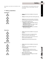
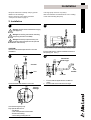
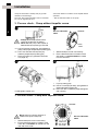
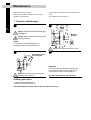
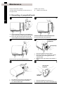
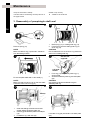
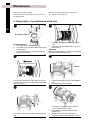
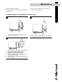
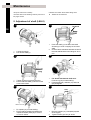
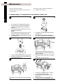
IM70737-GB7 9904 Operating Manual LKH Centrifugal Pump Declaration of Conformity The designating company Alfa Laval Company Name 6000 Kolding Address +45 79 32 22 00 Phone No. hereby declare that CENTRIFUGAL PUMP LKH Denomination Type Year is in conformity with the following directives with amendments: - Low Voltage Directive 73/23/EEC - EMC Directive 89/336/EEC - Machinery Directive 89/392/EEC Bjarne Søndergaard Name Alfa Laval Company Designation Vice President, R & D Title Signature Table of contents This manual is divided into main sections. - See below. Please note that the drawings on pages 25, 27 and 29 can be unfolded and support the reading of the manual. Safety 1. 2. 3. Important information ................................. 2 Warning signs ........................................... 2 Safety precautions .................................... 3 1 Installation 1. 2. 3. Unpacking/Delivery .................................... 4 Installation ................................................ 5 Pre-use check ........................................... 6 Operation 1. 2. 3. Operation/Control ...................................... 7 Fault finding .............................................. 8 Recommended cleaning ............................ 9 Maintenance 1. 2. 3. 4. 5. 6. General maintenance .............................. 10 Dismantling of pump/shaft seals ............. 12 Reassembly of pump/single shaft seal .... 14 Reassembly of pump/flushed shaft seal .. 16 Adjustment of shaft ................................. 18 Reassembly of pump/double mechanical shaft seal ............................. 20 Technical data 1. Technical data ......................................... 22 Drawings/Parts list 1. 2. 3. 4. 5. 6. Exploded drawing (LKH-5) ....................... 24 Drawing/Parts list (LKH-5) ....................... 25 Exploded drawing (LKH-10/-60) ............... 26 Drawing/Parts list (LKH-10/-60) ............... 27 Exploded drawing (LKH-70/-80) ............... 28 Drawing/Parts list (LKH-70/-80) ............... 29 Information 1. 2. Notes ...................................................... 30 User feedback ......................................... 30 Safety Unsafe practices and other important information are emphasized in this manual. Warnings are emphasized by means of special signs. 1. Important information Always read the manual before using the pump! 2 WARNING! : Indicates that special procedures must be followed to avoid severe personal injury. CAUTION! : Indicates that special procedures must be followed to avoid damage to the pump. NOTE! : Indicates important information to simplify practices or to make them clearer. : General warning. : Dangerous electrical voltage. : Caustic agents. 2. Warning signs Safety All warnings in the manual are summarized on this page. Pay special attention to the instructions below so that severe personal injury and/or damage to the pump are avoided. 3. Safety precautions Installation: : Always read the technical data thoroughly (see page 22). : Always use a lifting crane when handling the pump. : Always have the pump electrically connected by authorized personnel (see the motor instructions). : Pump without impeller screw: - Always remove the impeller before checking the direction of rotation. - Never start the pump if the impeller is fitted and the pump casing is removed. Pump with impeller screw: - Never start in the wrong direction of rotation with liquid in the pump. : Always read the technical data thoroughly (see page 22). : Never touch the pump or the pipelines when pumping hot liquids or when sterilizing. : Never run the pump with both the suction side and the pressure side blocked. : Always handle lye and acid with great care. : Always read the technical data thoroughly (see page 22). : Always disconnect the power supply when servicing the pump. : - Never service the pump when it is hot. - Never service the pump with pump and pipelines under pressure. : Motors with grease nipples: Remember lubrication according to information plate/label on the motor. Operation: Maintenance: 3 Installation The instruction manual is part of the delivery. Study the instructions carefully. The standard delivery does not include the test certificate. This can be supplied on request. The large pump sizes are very heavy. Alfa Laval therefore recommends the use of a lifting crane when handling the pump. 1. Unpacking/Delivery 1 4 2 Always use a lifting crane when handling the pump (see technical data). Remove packing materials! CAUTION! We cannot be held responsible for incorrect unpacking. Check the delivery for: 1. Complete pump. 2. Delivery note. 3. Motor instructions. 4. Test certificate, IF ORDERED!I Remove possible packing materials from the inlet and the outlet. 3 4 Inspection! Caution! Inspect the pump for visible transport damages. 5 Avoid damaging the inlet and the outlet. 6 Remove the shroud before lifting! Caution! Avoid damaging the connections for flushing liquid, if supplied. Always remove the shroud, if fitted, before lifting the pump. Installation Study the instructions carefully and pay special attention to the warnings! Always check the pump before operation. - See pre-use check on page 6. The large pump sizes are very heavy. Alfa Laval therefore recommends the use of a lifting crane when handling the pump. 2. Installation 1 2 5 Always read the technical data thoroughly (see page 22). Always use a lifting crane when handling the pump (see technical data). Always have the pump electrically connected by authorized personnel (see the motor instructions). CAUTION! We cannot be held responsible for incorrect installation. 3 Ensure that there is sufficient clearance around the pump (min. 0.5 m). 4 Outlet Remember seal rings! Correct! Few bends! Inlet Correct! 1. Check that the flow direction is correct. 5 Risk of damage! Avoid stressing the pump. Pay special attention to: - Vibrations. - Thermal expansion of the tubes. - Excessive welding. - Overloading of the pipelines. 2. Ensure that the pipelines are routed correctly. Ensure that the connections are tight. Installation Study the instructions carefully and pay special attention to the warnings! LKH-5 to -60 is without impeller screw as standard but can be supplied with one. Check the direction of rotation of the impeller before operation. - See the indication label on the pump. 3. Pre-use check - Pump without impeller screw 1 2 See the indication label! 6 Correct! - Always remove the impeller before checking the direction of rotation. - Never start the pump if the impeller is fitted and the pump casing is removed. 1a. LKH-5: Remove screws (56), spring washers (56a), clamps (55+55a) and pump casing (29). 1b. LKH-10 to -80: Remove cap nuts (24), washers (24a) and pump casing (29). 2. Remove impeller (27) (see also instruction 4 on page 12). 3 Stub shaft 1. 2. Start and stop the motor momentarily. Ensure that the direction of rotation of the stub shaft (7) is anticlockwise as viewed from the inlet side. 4 Fit and tighten impeller (27). 1. Fit pump casing (29). 2a. LKH-5: Fit clamps (55+55a), spring washers (56a) and tighten screws (56). 2b. LKH-10 to -80: Fit washers (24a) and tighten cap nuts (24). 3. Pre-use check - Pump with impeller screw Correct! Never start in the wrong direction of rotation with liquid in the pump. 1. 2. Start and stop the motor momentarily. Ensure that the direction of rotation of the motor fan is clockwise as viewed from the rear end of the motor. See the indication label! View from rear end of the motor Operation Study the instructions carefully and pay special attention to the warnings! The pump is fitted with a warning label indicating correct throttling. 1. Operation/Control 1 2 Burning danger! Always read the technical data thoroughly (see page 22). CAUTION! We cannot be held responsible for incorrect operation/control. Never touch the pump or the pipelines when pumping hot liquids or when sterilizing. 3 4 Explosion danger! Do not run dry! Correct! Wrong! See the warning label! Never run the pump with both the suction side and the pressure side blocked. 5 Correct! Free outlet CAUTION! The shaft seal must not run dry. Never throttle the inlet side. 6 Throttling! R1/8"(BSP) Tmax = 100oC Inlet Pmax = 1 bar (water) Flushed shaft seal: 1. Connect the inlet of the flushing liquid correctly. 2. Regulate the water and steam supply correctly. 3. Observe the steam data. Control: Reduce the capacity and the power consumption by means of: Throttling the pressure side of the pump. Reducing the impeller diameter. Reducing the speed of the motor. 7 Operation Pay attention to possible faults. Study the instructions carefully. 2. Fault finding 8 NOTE! Study the maintenance instructions carefully before replacing worn parts. - See page 10! Problem Cause/result Overloaded motor - Pumping of viscous liquids - Pumping of liquids with high density Remedy - Larger motor or smaller impeller - Low outlet pressure (counter pressure) - Higher counter pressure (throttling) - Lamination of precipitates from the liquid - Frequent cleaning - Damage - Low inlet pressure - Increase the inlet pressure - Pressure reduction (sometimes to zero) - High liquid temperature - Reduce the liquid temperature Cavitation: - Reduce the pressure drop before the pump - Increasing of the noise level - Reduce speed Leaking shaft seal - Dry run (See page 7) - Incorrect rubber grade Leaking seals Replace: All wearing parts (See page 10) If necessary: - Select a different rubber grade - Abrasive particles in the liquid - Select stationary and rotating seal ring in Silicon Carbide/ Silicon Carbide Incorrect rubber grade Replace with seals of a different rubber grade Operation The pump is designed for cleaning in place (CIP). CIP = Cleaning In Place. Study the instructions carefully and pay special attention to the warnings! NaOH = Caustic Soda. HNO3 = Nitric acid. 3. Recommended cleaning 1 2 Caustic danger! Burning danger! Always use rubber gloves! Always use protective goggles! Always handle lye and acid with great care. 3 4 Examples of cleaning agents: Use clean water, free from chlorides. 1. Never touch the pump or the pipelines when sterilizing. 1. 1% by weight NaOH at 70oC. 1 kg NaOH + 100 l water = Cleaning agent. 2.2 l + 33%NaOH 100 l water = Cleaning agent. 2. Avoid excessive concentration of the cleaning agent Þ Dose gradually! 2. Adjust the cleaning flow to the process Sterilization of milk/viscous liquids Þ Increase the cleaning flow! 0.5% by weight HNO3 at 70oC. 0.7 l + 53% HNO3 100 l water = Cleaning agent. 5 6 Always rinse! Water Cleaning agent Always rinse well with clean water after the cleaning. NOTE! The cleaning agents must be stored/disposed of in accordance with current rules/directives. 9 Maintenance Maintain the pump carefully. Study the instructions carefully and pay special attention to the warnings! Always keep spare shaft seals and rubber seals in stock. See separate motor instructions. 1. General maintenance 1 2 10 Always read the technical data thoroughly (see page 22). Burning danger! Always disconnect the power supply when servicing the pump. NOTE! All scrap must be stored/disposed of in accordance with current rules/directives. Never service the pump when it is hot. 3 4 Atmospheric pressure required! Never service the pump with pump and pipelines under pressure. CAUTION! Fit the electrical connections correctly if they have been removed from the motor during service (see pre-use check on page 6). Pay special attention to the warnings! Ordering spare parts - Contact the Sales Department. - Order from the Spare Parts List. Recommended spare parts: Service kits (see Spare Parts List). Maintenance Maintain the pump carefully. Study the instructions carefully. Always keep spare shaft seals and rubber seals in stock. See separate motor instructions. Check the pump for smooth operation after service. 1. General maintenance Shaft seal Rubber seals Preventive maintenance Replace after 12 months: (one-shift) Complete shaft seal Replace when replacing the shaft seal Maintenance after leakage (leakage normally starts slowly) Replace at the end of the day: Complete shaft seal Replace when replacing the shaft seal Planned maintenance - Regular inspection for Replace when replacing leakage and smooth the shaft seal operation - Keep a record of the pump - Use the statistics for planning of inspections Replace after leakage: Complete shaft seal Lubrication Before fitting Lubricate the O-rings with silicone grease or silicone oil Before fitting Silicone grease or silicone oil Motor bearings Yearly inspection is recommended - Replace complete bearing if worn - Ensure that the bearing is axially locked (See motor instructions) See below (*) Pre-use check CAUTION! Fit the electrical connections correctly if they have been removed from the motor during service. (See pre-use check on page 6). Pay special attention to the warnings! 1. Start and stop the motor momentarily. 2. Ensure that the pump operates smoothly. (*) Lubrication - motor bearings: Motors without grease nipples are permanently lubricated and do therefore not need any lubrication. Lubrication intervals for motors with grease nipples are shown on the information plate on the motor. The lubrication intervals are based upon 80o C bearing temperature. The values should be halved for every 15o C increase in the bearing temperature. Note! Motors with grease nipples should be lubricated before operating the first time! 11 Maintenance Study the instructions carefully. The items refer to the drawings and the parts list on the pages 24-29. Handle scrap correctly. : Relates to the shaft seal. 2. Dismantling of pump/shaft seals 1 2 12 1a. LKH-5: Remove screws (56), spring washers (56a), clamps (55+55a) and pump casing (29). 1b. LKH-10 to -80: Unscrew cap nuts (24) and remove washers (24a) and pump casing (29). Flushed / Double mechanical shaft seal: Unscrew tubes (42) using a spanner. 4 3 Counterhold with a screwdriver! If necessary! 1. 2. Remove screw (23) and safety guard (22). 5 3. Remove impeller screw (36), if fitted. Remove impeller (27). If necessary, loosen the impeller by knocking gently on the impeller vanes. Remove the O-ring (38) from the impeller, if fitted. 6 Use the tool supplied! Left hand thread! 1. 2. Pull off the O-ring (26) from back plate (25). Unscrew nuts (20) and remove washers (21) and the back plate. 1. 2. Remove the stationary seal ring (11). Remove the O-ring (12) from back plate (25). Maintenance Study the instructions carefully. The items refer to the drawings and the parts list on the pages 24-29. Handle scrap correctly. : Relates to the shaft seal. 2. Dismantling of pump/shaft seals 7 8 13 Flushed shaft seal: 1. Remove screws (41) and seal housing (40). 2. Pull out lip seal (43) from the seal housing. 9 Double mechanical shaft seal: 1. Remove stationary seal ring (51) from seal housing (40a). 2. Remove O-ring (50) from stationary seal ring (51). 3. Remove O-ring (44) from seal housing (40a). Double mechanical shaft seal: 1. Remove screws (41) and seal housing (40a). 2. Remove rotating seal rings (14) and drive ring (52) from spring (13). 3. Remove O-rings (15) from rotating seal rings (14). 10 1. 2. Remove the complete shaft seal from stub shaft (7). Remove spring (13) and rotating seal ring (14) from the drive ring (10). Maintenance Study the instructions carefully. The items refer to the drawings and the parts list on the pages 24-29. Handle scrap correctly. : Relates to the shaft seal. 3. Reassembly of pump/single shaft seal 1 2 14 1. 2. Remove spring (13). NOTE! Make sure that O-ring (15) has max. clearance from the sealing surface. 3 Refit spring (13) on rotating seal ring (14). Fit the spring and the rotating seal ring on drive ring (10). CAUTION! Ensure that the driver on the drive ring enters the notch in the rotating seal ring. 4 Use the tool supplied! Left hand thread! 1. Fit the complete shaft seal on stub shaft (7). NOTE! Make sure that connex pin (8) on the stub shaft enters the notch in drive ring (10). 5 1. 2. 3. Clean the sealing surfaces with contact cleaner before fitting back plate (25). Carefully guide the back plate onto adaptor (16). Fit washers (21) and nuts (20). Fit O-ring (12) on stationary seal ring (11) and lubricate. 2. Screw the stationary seal ring into back plate (25). CAUTION! Only tighten by hand to avoid deforming the stationary seal ring. 6 Lubricate O-ring (26) and slide it onto back plate (25). Maintenance Study the instructions carefully. The items refer to the drawings and the parts list on the pages 24-29. Lubricate the rubber seals before fitting them. 3. Reassembly of pump/single shaft seal 7 8 15 1. 2. 3. 4. Lubricate O-ring (38) and fit it in impeller (37), if impeller screw is used. Lubricate the impeller hub with silicone grease or oil. Screw the impeller onto stub shaft (7). Fit impeller screw (36) and tighten, if used. 9 1a. LKH-5: Fit pump casing (29), clamps (55+55a), spring washers (56a) and screws (56). 1b. LKH-10 to-80: Fit pump casing (29), washers (24a) and cap nuts (24). 2. Adjust pump casing to the right position. 3a. LKH-5: Tighten nuts (20) for back plate (25) and tighten screws (56). 3b. LKH-10 to -80: Tighten nuts (20) for back plate (25) and tighten cap nuts (24). Fit safety guard (22) and screw (23) and tighten. Maintenance Study the instructions carefully. The items refer to the drawings and the parts list on the pages 24-29. Lubricate the rubber seals before fitting them. : Relates to the shaft seal. 4. Reassembly of pump/flushed shaft seal 1 2 16 Use ø63 mm tube! Flushed shaft seal: 1. Fit lip seal (43) in seal housing (40). 2. Lubricate O-ring (44) and slide onto the seal housing (40). 3. Fit the seal housing on back plate (25) and tighten screws (41). 3 Fit complete shaft seal on stub shaft (7) so that connex pin (8) on the stub shaft enters the notch in drive ring (10). 5 1. Lubricate O-ring (45) and fit it in drive ring (10). 2. Fit spring (13) and rotating seal ring (14) on the drive ring. CAUTION! Make sure that the driver on the drive ring enters the notch in the rotating seal ring. 4 1. 2. 6 1. 2. Lubricate O-ring (26) and slide it onto back plate (25). Carefully guide back plate (25) onto adaptor (16). Fit washers (21) and nuts (20). 3. 4. Lubricate O-ring (38) and fit it in impeller (37), if impeller screw is used. Lubricate the impeller hub with silicone grease or oil. Screw impeller (27) onto stub shaft (7). Fit impeller screw (36) and tighten, if used. Maintenance Study the instructions carefully. The items refer to the drawings and the parts list on the pages 24-29. Lubricate the rubber seals before fitting them. : Relates to the shaft seal. 4. Reassembly of pump/flushed shaft seal 7 8 17 1. 2. Screw tubes (42) into seal housing (40). Tighten with a spanner. 9 1a. LKH-5: Fit pump casing (29), clamps (55+55a), spring washers (56a) and screws (56). 1b. LKH-10 to -80: Fit pump casing (29). 2. Tighten nuts (20) for back plate (25). 3a. LKH-5: Tighten nuts (20) for back plate (25) and tighten screws (56). 3b. LKH-10 to -80: Fit washers (24a) and cap nuts (24) and tighten. Fit safety guard (22) and screw (23) and tighten. Maintenance Study the instructions carefully. The items refer to the drawings and the parts list on the pages 24-29. Lubricate the rubber seals before fitting them. : Relates to the shaft seal. 5. Adjustment of shaft (LKH-5) 2 1 10-20 mm 18 1. 1. 2. Loosen screws (4). Pull off stub shaft (7). 4 3 1. 2. 2. Push stub shaft (7) onto the motor shaft. Screws (4) must fit in keyway on the motor shaft. Check that the clearance between the end of the stub shaft and the motor flange is 10-20 mm. Tighten screws (4) lightly and evenly. Ensure that stub shaft (7) can be moved on the motor shaft. 5 1. 2. For double mechanical shaft seal: Fit drive ring (52) on stub shaft (7). Fit back plate (25), washers (21) and nuts (20) and tighten. 6 18 Nm LKH-5 = 0.5 mm 1. 2. Fit impeller (27) on stub shaft (7). Ensure that the clearance between the impeller and back plate (25) is correct: 0.5 mm for LKH-5. 1. 2. Remove impeller (27), back plate (25) and drive ring (52). Tighten screws (4) evenly to 18 Nm. Maintenance Study the instructions carefully. The items refer to the drawings and the parts list on the pages 24-29. Lubricate the rubber seals before fitting them. : Relates to the shaft seal. 5. Adjustment of shaft (LKH-10 to -80) 2 1 1 10-20 mm 19 1. 1. 2. Loosen screws (6). Pull off stub shaft (7) together with compression rings (5a, 5b). 4 3 1. 2. 2. Push stub shaft (7) together with compression rings (5a, 5b) onto the motor shaft. Check that the clearance between the end of the stub shaft and the motor flange is 10-20 mm. Tighten screws (6) lightly and evenly. Ensure that stub shaft (7) can be moved on the motor shaft. 5 1. 2. 6 LKH 10-60 = 0.5 mm LKH 70/-80= 1.0 mm Fit impeller (27) on stub shaft (7). Ensure that the clearance between the impeller and back plate (25) is correct: 0.5mm for LKH-10-60 and 1.0 mm for LKH-70/-80. NOTE! If pump has been ordered with increased clearence between impeller and backplate this additional clearence must be taken into account when adjusting the shaft. For double mechanical shaft seal: Fit drive ring (52) on stub shaft (7). Fit back plate (25), washers (21) and nuts (20) and tighten. Counterhold with a screwdriver 15Nm 1. 2. 1. 2. Remove impeller (27), back plate (25) and drive ring (52). Tighten screws (6) evenly to 15 Nm. Maintenance Study the instructions carefully. The items refer to the drawings and the parts list on the pages 24-29. Lubricate the rubber seals before fitting them. : Relates to the shaft seal. 6. Reassembly of pump/double mechanical shaft seal 1 2 1 20 1. 2. 3. 4. 3 Fit O-rings (15) in rotating seal rings (14). Fit spring (13) on one of the rotating seal rings (14) and place the drive ring (52) in between. Fit the second rotating seal ring (14) on the other end of the spring. NOTE: Ensure that both drive pins on the drive ring enters the notches in rotating seal rings. Place the parts on the stationary seal ring fitted in back plate (25). 1. 2. 4 1. 1. 2. Clean the sealing surfaces with contact cleaner. Fit seal housing (40a) on the back plate (25) and tighten screws (41). 5 2. 3. To enable fitting back plate (25) with the shaft seal remove connex pin (8) from stub shaft (7) (if fitted). Carefully guide the back plate onto adaptor (16). Fit washers (21) and nuts (20). 6 1. 2. Lubricate O-ring (26) and slide it onto back plate (25). Lubricate O-ring (44) and slide onto seal housing (40a). Lubricate O-ring (50) and fit on stationary seal ring (51) and fit this in the seal housing. 3. 4. Lubricate O-ring (38) and fit it in impeller (37), if impeller screw is used. Lubricate the impeller hub with silicone grease or oil. Screw impeller (27) onto stub shaft (7). Fit impeller screw (36) and tighten, if used. Maintenance Study the instructions carefully. The items refer to the drawings and the parts list on the pages 24-29. Lubricate the rubber seals before fitting them. : Relates to the shaft seal. 6. Reassembly of pump/double mechanical shaft seal 7 8 1 21 1. 2. Screw tubes (42) into seal housing (40a). Tighten with a spanner. 9 1. Fit pump casing (29). 2. Tighten nuts (20) for back plate (25). 3a. LKH-5: Fit clamps (55+55a), spring washers (56a) and screws (56) and tighten. 3b. LKH-10 to 80: Fit washers (24a) and cap nuts (24) and tighten. Fit safety guard (22) and screw (23) and tighten. Technical data It is important to observe the technical data during installation, operation and maintenance. Inform the personnel about the technical data. 1. Technical data Data 22 Max. inlet pressure LKH-5: ............................ 600 kPa (6 bar) LKH-10 to -80: ................ 1000 kPa (10 bar) Temperature range ............................................. -10o C to +140o C (EPDM) Noise level .......................................................... 60-80 dB (A) Materials Product wetted steel parts ................................. AISI 316L Other steel parts ................................................ AISI 304 Finish ................................................................. Semi-bright Product wetted seals ......................................... EPDM (standard) Other O-rings ..................................................... EPDM Alternative seals ................................................. Nitrile (NBR), Fluorinated rubber (FPM) and FEP Shaft seal Seal types .......................................................... External single, flushed or double mechanical seal .......................................................................... (Double mechanical seal NOT valid for LKH-70/-80) Max. water pressure (flushed seal) ..................... Normally atmospheric (max. 1 bar) Water consumption (flushed seal) ...................... 0.25 - 0.5 l/min. Max. water pressure (double mechanical seal) ... Normally atmospheric (max. 10 bar) Water consumption (double mechanical seal) .... 0.25-0.5 l/min. Material, stationary seal ring .............................. Acid resistent steel with sealing surface of Silicon Carbide Material, rotating seal ring .................................. Carbon (standard) or Silicon Carbide Material, O-rings ................................................ EPDM (standard) Alternative material, O-rings ............................... Nitrile (NBR), Fluorinated rubber (FPM) and FEP Motor Foot-flanged motor acc. to IEC metric standard 2 poles = 3000/3600 rpm. at 50/60 Hz IP55 (drain hole with labyrinth plug), insulation class F ( ( Voltage and frequency (standard) ....................... 3~, 50 Hz, 220-240V∆/380-420VY 3~, 60 Hz, 250-280V∆/440-480VY 3~, 50 Hz, 380-420V∆/660-690VY 3~, 60 Hz, 440-480V∆ ≤ 4 kW ≤ 4.6 kW ≥ 5.5 kW ≥ 6.3 kW ) ) Motor sizes (kW), 50 Hz .................................... 0.75, 1.1, 1.5, 2.2, 3.0, 4.0, 5.5, 7.5, 11.0, 15.0, 18.5, .......................................................................... 22.0, 30.0, 37.0, 45.0, 55.0, 75.0 Motor sizes (kW), 60 Hz .................................... 0.9, 1.3, 1.75, 2.5, 3.5, 4.6, 6.3, 8.6, 12.5, 17.0, 21.0, .......................................................................... 25.0, 35.0, 43.0, 52.0, 63.0, 86.0 Max. weight for LKH-pumps ............................... LKH-5: 33 kg, LKH-10: 57 kg, LKH-15: 79 kg, .......................................................................... LKH-20: 77 kg, LKH-25: 134 kg, LKH-35: 134 kg, .......................................................................... LKH-40: 174 kg, LKH-45: 136 kg, LKH-50: 174 kg, .......................................................................... LKH-60: 327 kg, LKH-70: 570 kg, LKH-80: 581kg. For further information - see PD-sheet. 23 Exploded drawing This page shows an exploded drawing of LKH, sanitary version. The drawing includes all items of the pump. They are identical with the items in the Spare Parts List. LKH-5, Sanitary version 24 Parts for double mechanical shaft seal Parts for flushed shaft seal Drawing/Parts list Click here to Order Parts The drawing and the parts list include all items of the pump. The items are identical with the items in the Spare Parts List. When ordering spare parts, please, use the Spare Parts List. The drawing shows LKH, sanitary version. LKH-5, Sanitary version Parts list Pos. 1 2 2a 3 4 7 8 10 11 12 13 14 15 16 17 18 19 20 21 22 23 25 26∆ 27 29 30a 30b 31 32 33 34 35 35a 36 37 38 39 40 40a 41 42 43∆ 44∆ 45∆ 50∆ 51 52 55 55a 56 56a Qty. 1 1 1 4 2 1 1 1 1 1 1 1 2 1 2 1 4 4 4 2 2 1 1 1 1 1 1 1 1 4 4 4 4 4 4 1 1 1 4 1 1 2 2 1 1 1 1 1 1 1 1 2 2 The items refer to the parts list on the opposite part of the page. Denomination Motor Shroud Edge list Screw Screw Shaft Connex pin Drive ring Stationary seal ring O-ring Spring Rotating seal ring Rotating seal ring O-ring O-ring Adaptor Screw for adaptor Nut for adaptor Washer for adaptor Nut Washer Safety guard Screw for safety guard Back plate O-ring Impeller Pump casing Support bar, right Support bar, left Leg Screw Nut Spring washer Screw Washer Impeller screw Impeller for impeller screw O-ring Nut Seal housing Seal housing Screw for seal housing Tube Lip seal O-ring for seal housing O-ring for drive ring O-ring Sec. stationary seal ring Drive ring Upper clamp Lower clamp Screw Spring washer 25 n n l Flushed shaft seal l Double mechanical shaft seal n l nl nl n nl n l l l ∆ : n : l : Service kit - EPDM, NBR, FPM, FEP (see spare parts list). Impeller screw Flushed shaft seal. Double mechanical shaft seal. Only used for 0.75 and 1.1 kW Fitting of legs Fitting of back plate Exploded drawing Drawing/Parts list This page shows an exploded drawing of LKH, sanitary version. LKH-10, -15, -20, -25, -35, -40, -45, -50, -60, Sanitary version LKH-5, Sanitary version 25 The drawing includes all items of the pump. They are identical with the items in the Spare Parts List. 26 Parts for double mechanical shaft seal Parts for flushed shaft seal (30 kW) Click here to Order Parts The drawing and the parts list include all items of the pump. Drawing/Parts list The items are identical with the items in the Spare Parts List. When ordering spare parts, please, use the Spare Parts List. Parts list Denomination 1 2 2a 3 5a 5b 6 6a 7 8 9 10 11 12 13 14 Motor Shroud Edge list Screw Compression ring with thread Compression ring without thread Screw Washer Shaft Connex pin Retaining ring Drive ring Stationary seal ring O-ring Spring Rotating seal ring n Rotating seal ring l O-ring n O-ring l Adaptor Screw for adaptor Nut for adaptor Washer for adaptor Nut Washer Safety guard Screw for safety guard Cap nut Washer Back plate O-ring Impeller Stud bolt Pump casing Support bar, right Support bar, left Leg Screw Nut Spring washer Screw Washer Impeller screw Impeller for impeller screw O-ring Nut Seal housing n Seal housing l Screw for seal housing nl Tube nl Lip seal n O-ring for seal housing nl O-ring for drive ring n Distance sleeve O-ring l Sec. stationary seal ring l Drive ring l Centre screw (30 kW only) 15 16 17 18 19 20 21 22 23 24 24a 25 26∆ 27 28 29 30a 30b 31 32 33 34 35 35a 36 37 38 39 40 40a 41 42 43∆ 44∆ 45∆ 46 50∆ 51 52 53 The items refer to the parts list on the opposite part of the page. LKH-10, -15, -20, -25, -35, -40, -45, -50, -60, Sanitary version Pos. Qty. 1 1 1 4 1 1 6 6 1 1 1 1 1 1 1 1 2 1 2 1 4 4 4 2 2 1 1 6 6 1 1 1 6 1 1 1 4 4 4 4 4 4 1 1 1 4 1 1 2 2 1 1 1 4 1 1 1 4 The drawing shows LKH, sanitary version. 27 Flushed shaft seal Double mechanical shaft seal ∆ : n : l : Service kit - EPDM, NBR, FPM, FEP (see spare parts list). Impeller screw Flushed shaft seal. Double mechanical shaft seal. Only used for 5.5 - 30 kW Only used for 3 kW Fitting of legs Fitting of back plate Drawing/Parts list Exploded drawing This page shows an exploded drawing of LKH, sanitary version. LKH-10, -15, -20, -25, -35, -40, -45, -50, -60, Sanitary version 27 The drawing includes all items of the pump. They are identical with the items in the Spare Parts List. LKH-70, -80, Sanitary version 28 Parts for flushed shaft seal (30 - 45 kW) Legs Click here to Order Parts The drawing and the parts list include all items of the pump. Parts list Pos. 1 2 2a 3 5a 5b 6 6a 7 8 10 11 12 13 14 15 16 17 18 19 20 21 22 23 24 24a 25 26∆ 28 29 30a 30b 31 32 33 34 35 35a 36 37 38 40 41 42 43∆ 44∆ 45∆ 46 47 48 49 53 Qty. 1 1 1 4 1 1 6 6 1 1 1 1 1 1 1 1 1 4 4 4 4 4 1 1 8 8 1 1 8 1 1 1 4 4 4 4 4 4 1 1 1 1 2 2 1 1 1 4 2 4 4 4 Drawing/Parts list The items are identical with the items in the Spare Parts List. When ordering spare parts, please, use the Spare Parts List. The drawing shows LKH, sanitary version. The items refer to the parts list on the opposite part of the page. LKH-70, -80, Sanitary version Denomination Motor Shroud Edge list Screw Compression ring with thread Compression ring without thread Screw Washer Shaft Connex pin Drive ring Stationary seal ring O-ring Spring Rotating seal ring O-ring Adaptor Screw for adaptor Nut for adaptor Washer for adaptor Nut Washer Safety guard Screw for safety guard Cap nut Washer Back plate O-ring Stud bolt Pump casing Support bar, right Support bar, left Leg Screw Nut Spring washer Screw Washer Impeller nut Impeller O-ring Seal housing n Screw for seal housing n Tube n Lip seal n O-ring for seal housing n O-ring for drive ring n Distance sleeve Leg bracket Nut for leg bracket Screw for leg Centre screw (30-45 kW) ∆ : Service kit - EPDM, NBR, FPM (see spare parts list) n : Flushed shaft seal 29 Fitting of back plate Flushed shaft seal Fitting of legs 55 - 75 kW