1
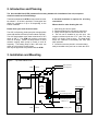
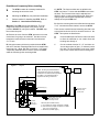
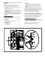
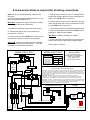
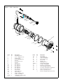
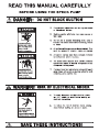
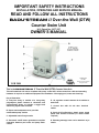
IMPORTANT SAFETY INSTRUCTIONS
INSTALLATION, OPERATING AND SERVICE MANUAL
READ AND FOLLOW ALL INSTRUCTIONS
®
BADU STREAM II Over-the-Wall (OTW)
Counter Swim Unit
U.S. Patent No. 3.977.027
OWNER’S MANUAL
Complies with
UL 1583
Swimming Pool Equipment
Listing #E212148
VGB 2008
This is the BADUSTREAM II Over-the-Wall (OTW) Counter Swim Unit
This self-contained unit comes complete with pump, control box, unit-to-control box cable and mounting
hardware. It requires no additional equipment for installation. Just supply pool, water and electricity.
Key to illustration:
A. One-piece body is molded of a heavy-duty
polyethylene plastic immune to chemicals and
environmental abuse, to provide a rugged and
attractively styled water treadmill.
B. Square anti-entrapment cover provides
undetectable pump suction.
C. Adjustable water flow jet nozzle.
D. Pneumatic on/off button guarantees complete
separation between pool water and pump motor
control.
E. Air regulator controls amount of air bubbles in
water flow.
F. Control box with 24 volt door interlock
switch.
G. Speck 4 HP self-priming, plastic pump, single
phase with thermal overload (no motor starter
required)
H. Pulsating massage hose can be attached to jet
nozzle.
TABLE OF CONTENTS
1.
Important Safety Instructions . . . . . . . . . . . . . . . . Page 3
2.
Introduction and Planning . . . . . . . . . . . . . . . . . . . Page 4
3.
Installation and Mounting . . . . . . . . . . . . . . . . . . . Page 4
4.
Top View of Unit Without Cover . . . . . . . . . . . . . . Page 4
5.
Side View of Unit (Layout) . . . . . . . . . . . . . . . . . . . Page 5
6.
Electrical Wiring and Diagram . . . . . . . . . . . . . . . Page 7
7.
Operating Instructions . . . . . . . . . . . . . . . . . . . . . . Page 8
8.
Winterizing . . . . . . . . . . . . . . . . . . . . . . . . . . . . . . . Page 8
9.
Frequently Asked Questions . . . . . . . . . . . . . . . . . Page 9
10. Parts List and Exploded View of Pump . . . . . . . . Page 9
11. Parts List and Exploded View of Jet . . . . . . . . . . Page 10
12. Limited Warranty . . . . . . . . . . . . . . . . . . . . . . . . . Page 11
IMPORTANT INSTALLATION TIPS IN BOLD PRINT
1. IMPORTANT SAFETY INSTRUCTIONS
When installing and using this electrical equipment, basic safety precautions should always be followed,
including the following:
READ AND FOLLOW ALL INSTRUCTIONS.
A.
WARNING: To reduce the risk of injury, DO NOT
permit children to use this equipment unless they
are closely supervised at all times. Failure to
adhere to this and all other warnings could result in
serious injury or death.
B. WARNING: Consult your physician before
exercising with the OTW unit or using the
massage hose.
C. WARNING: Stay alert, watch what you are doing
and use common sense. DO NOT use OTW unit
if you are tired and/or exhausted. DO NOT use
OTW unit while under the influence of drugs,
alcohol, or any medication.
D. WARNING: DO NOT use or operate the OTW unit
if the square, anti-entrapment cover is missing,
broken or loose.
E. WARNING: DO NOT step on or dive from the
OTW unit.
F. WARNING: DO NOT step on the handles.
G. WARNING: DO NOT store or use gasoline or
other flammable vapors or liquids in the vicinity of
this equipment. DO NOT store pool chemicals
near the equipment.
H. All electrical equipment should be installed in
accordance with local codes.
I.
WARNING: Use ONLY copper conductors with a
minimum 75 degrees C wire insulation.
J. WARNING: Use ONLY non-conductive tubing to
connect between air switch and air transmitter
(button).
K. TO REDUCE RISK OF ELECTRICAL SHOCK,
connect all ground wires to grounding terminal
located in the control box. Use no smaller than a
No. 12 AWG (3.3 mm2) wire.
L. TO REDUCE RISK OF ELECTRICAL SHOCK, a
bonding connector is provided on the motor for
bonding of local ground points such as water pipes,
metal ladders/handrails, or other metal within 5 feet
of the pool. All local ground points should be
bonded with a No. 8 AWG (8.4 mm2) wire. Never
use gas piping as an electrical ground.
M. TO REDUCE RISK OF ELECTRICAL SHOCK
,turn all power off at breaker or service disconnect,
before installing or servicing equipment.
N. TO REDUCE RISK OF ELECTRICAL SHOCK,
never attempt to jump, bypass or crossover any
wiring connections. One wiring error will cause
permanent internal damage.
O. A licensed electrician is required for all
wiring connections.
P. WARNING: The control box is provided with a
ground-fault circuit-interrupter (GFCI) located on
the left side of the box. The GFCI must be tested
before each use. With the product operating, open
the GFCI cover and push the test button. This
should turn off the product. Next, reset the GFCI
and the product should operate normally. If the
control fails to operate in this manner, disconnect
the power until the fault has been identified and
corrected.
Q. DO NOT remove any safety alert labels such as
DANGER, WARNING or CAUTION. Keep safety
alert labels in good condition and replace missing
or damaged labels.
R. KEEP
AND
READ
ALL EQUIPMENT
MANUALS. Adhere to all of their instructions.
S. SAVE THESE INSTRUCTIONS! Refer to them
frequently and use them to instruct third party
users.
SAVE THESE INSTRUCTIONS
2. Introduction and Planning
The Over-the-Wall Unit (OTW) contains all necessary hardware for installation of the unit, except the
electrical conduit and conduit fittings.
The distance between the OTW and the control box must
be at least 5'. 25' of wire is provided. This length of wire
allows for a distance of up to 20' depending on the
location variables.
A licensed electrician is required for all wiring
connections.
Please check your local electrical codes.
1. Main wiring and service panel.
2. Distance between the unit and it's control box.
3. Plenty of deck space to walk around the unit.
4. The unit can be installed in any size pool. We
suggest a minimum pool size of 7 ft. wide, 14 ft. long
and 3 ½ ft. deep in order to swim. The extra length
allows the swimmer to comfortably drift back and
swim upstream.
5. Control box must be placed in a location that is
easily accessible to the pool user to check the GFCI.
The 4 HP, self-priming, plastic pump has a single phase
motor with thermal overload (no motor starter required ).
The 4 HP single phase motor draws a maximum of 19.4
amps at 230 V. The OTW unit requires a minimum
circuit of 30 amps. Install a 40 amp breaker to avoid
nuisance tripping when pump is turned on and off
frequently. The starting amps of the 4 HP motor can
reach up to 6 times the running amps.
Use only the approved wire provided with the OTW.
What to look for when locating the unit:
3. Installation and Mounting
Figure 1 - Top View without Cover
Mfg. Date Code
Pool
Mounting Holes
Deck
Control
Box
24 Volts
Air Tubing
Pump
Mounting
Area
Interlock Position Switch
GFCI Test Access
3" x 5" Oval Hole
24 Volt Wiring Conduit
Maximum 15'
Mounting Holes
Service
Deck
Disconnect
Pool
Control Box
230 Volt Wiring Conduit
Read Manual Completely Before Installing
#
The OTW contains all necessary hardware for
mounting the unit to the deck.
#
Mounting the OTW may vary with each installation.
#
Review location for installing the OTW. Refer to
Section 2 . Introduction and Planning
Warning: The OTW is heavy and awkward. The Unit
weights 150 lbs and will require a two person crew to
position. DO NOT lift unit by the handles. DO NOT drop
the unit into the pool!
A. Remove the cover from the OTW, place the unit on the
deck where it is going to be mounted. Use the unit as a
template to locate the anchor holes and oval electrical
3" x 5" hole.
B. Using the masonry bit that is provided with the OTW,
drill one of the back mounting holds first, then install brass
insert into hole. (Note: Drill hole in concrete 1 1/4" deep.)
Temporarily install M-8 bolt in insert to secure the OTW
while the remaining holes are being drilled.
C. NOTE: The front two holes are not drilled in the
OTW unit’s base. To insure that the OTW is secured to
the deck. The front two holes may be adjusted and
drilled for brick or coping deck edged pools. Brick and
coping maybe removed and replaced with concrete.
Attempt to keep the OTW level.
D. Once the mounting holes are drilled and the electrical
3” x 5” oval hole has been marked, remove the OTW.
There are two conduit lines and a bonding wire that have
to be placed under the deck for electrical service to the
OTW. Two options are listed below.
#
Cut and install a piece of Deck-o-drain in the deck
to allow the electrician to run conduit lines and
bonding wire through it.
#
Cut the marked electrical 3" x 5" oval hole out.
Jet one larger piece of pipe ( 2" minimum) under
the deck, for the electrician to use as a casing
pipe for two conduit lines and the bonding wire.
Minimum 5'
Figure 2 - Layout
GFCI Test
Access
NOTE: All wiring is provided between
control boxes and pump (25' provided).
Conduit and connectors must be provided
by installer. A licensed electrician is
required for all wiring connections.
30"
Control
Box
Service
Disconnect
Priming Plug
Motor Bonding Lug
8"
Deck
10"
Water
Line
Pool Wall
Air Tubing to Air Control
Lower Unit
Wall Support
Bonding Wire No. 8 AWG
24 Volt Wiring Conduit
230 Volt Wiring Conduit
Wire List (25' Provided of each)
A. 24 volt wires (2 copper conductors 14 AWG)
B. 230 volt wires (3 copper conductors 12 AWG
line 1, line 2 and ground)
C. Bond wire (8 AWG copper)
Bond wire must be
bonded to local
ground points
Mounting the OTW to the deck may vary with each
installation.
Instructions:
1. Press the brass insert into the pre-drilled hole.
2. Install the rubber mount with threaded stud into
the two brass inserts at rear of unit. Tighten down
completely.
3. Place the OTW on the rubber mounts. Install flat
washers, lock washers and bolts. Use M8 x 20mm
bolts for the rear and M8 x 40mm for the front of the
installation. Tighten all bolts completely.
4. Adjust lower wall supports to level OTW.
# Decks with coping: The coping has to be
removed where the OTW is being installed.
# Brick decks: The brick has to be removed and
replaced with concrete.
# Wood decks: The OTW has to be bolted all the
way through the wood. (Hardware not provided for
this installation)
The center of the housing (the nozzle) should be
10" to 13" below the water level for maximum
efficiency.
NOTE: If the slope of the deck is greater than 1" in
12" use the rubber mount on the rear mounting holes
only, i.e. mount the front of unit directly to the deck.
If the slope is less, do not use rubber mounts. Use
the four M8 X 40 bolts to secure OTW to deck.
Top Deck to Water Line 7"
Pools that have approximately 7” between the top of
the deck and water level.
Anchor Parts:
# Brass insert
# Rubber mount w/threaded stud
# Lock washer
# Bolt M8 x 20mm
# Bolt M8 x 40 mm
# Fender washer
Top Deck to Water Line 3" to 5"
Pools that have approximately 3" - 5" between the
top of the deck and water level require a customizing
kit with spacers to raise the OTW.
Qty
4
2
4
2
4
4
Please call for optional lift kit. Phone number is
available on back cover of this manual.
Figure 3 - Side View Cutaway
30 "
Priming Plug
16"
4
5
Deck
8"
Water Line
28"
10"
Pool Wall
Air Hose to Air Control
Lower Unit
Wall
Support
3
2
1
A licensed electrician is required for all wiring connections.
1. Connect load 1 black wire to line 1 connection at the
pump motor and the other end of wire to terminal No.5
(load 1) in the OTW-7-GFCI control box.
Note: All wiring is provided between control boxes
and pump.
Use only the approved wire provided with the unit. The
three wire sets are labeled A, B, C.
2. Connect load 2 red wire to line 2 connection at pump
motor and the other end of wire to terminal No.6 (Load
2) in the OTW-7-GFCI control box.
Wire Set A consists of 2 copper conductors 14 AWG,
and is used for the 24 volt connections.
1. Each wire is labeled for each terminal connection.
3. The green ground wire is connected to ground screw
in pump motor and ground terminal in the OTW-7-GFCI
control box. Refer to wiring diagram.
2. Connect each wire in the 24 volt control box to
terminals No.1 and No.2.
Wire Set C consists of bonding wire 8 AWG.
3. Connect each wire in the OTW-7GFCI control box to
terminals No.8 and No.9. Refer to wiring diagram.
1. Connect bonding wire to bonding lug on pump motor
and the other end to an approved local ground point.
Wire set B consists of 3 copper conductors 10 AWG,
and is used for the 230 volt connections. Each wire
is labeled for each terminal connection.
MODEL OTW-7-GFCI
Refer to Figure 2, Page 5.
MODEL OTW-7-GFCI
WHT-4
CONTACTOR
WHT-2
WHT-3
BLK-5
BLK-7
LOAD
GFCI
BLK-1
RED-1
BLK-2
Coil
24 V
BLK-4
CONTACTOR
BLU-2
WHT-1
GRN-1
Torque
in.-lbs.
Wire
Range
14-10 CU
7
8 CU
10
READ AND FOLLOW ALL INSTRUCTIONS
YEL-1
Fuse Holder
with Fuse
BLK-4
T0RQUE DATA
SAFETY INSTRUCTIONS
Transformer
BLU-1
LINE
1-Circuit 30 Amps
208-240 Volts
60 Hz, 1 Phase
4-Wire Service
GFCI Protected
ON/OFF Controls
Coil
120 V
BLK-3
OTW-7 RATING
SPECK PUMPS
8125 BAYBERRY ROAD
JACKSONVILLE, FLORIDA 32256
PHONE: (904) 739-2626
FAX: (904) 737-5261
www.usa.speck-pumps.com
RED-2
RED-3
GFCI
TRANSFORMER
WARNING: This control is provided with a ground-fault circuit-interrupter (GFCI) located on the left side
of the box. The GFCI must be tested before each use. With the product operating, open GFCI cover
and push the test button. This should turn off the product. Next, reset the GFCI and the product should
operate normally. If the control fails to operate in this manner, disconnect the power until the fault has
been identified and corrected.
WARNING: Use ONLY copper conductors with a minimum 75 degree C wire insulation.
WARNING: A Service Disconnect is required for this product. The Service Disconnect must be
provided by owner and installed by a licensed electrician according to instruction and local codes.
WARNING: Use ONLY non-conductive tubing to connect between air switch and air transmitter (button).
WARNING: All connections shown in wiring diagram MUST be used. Never attempt to jump, by-pass
or crossover any connections. One wiring error will cause permanent internal damage.
NOTE: Bonding connections not shown and vary with installation.
Control Box 24 Volts
Pump
208-240 Volts, 60 Hz, 30 amps, 1 Phase
7 8 9
N/O
1 2 3
From Control Box 24 Volts
To Control Box 24 Volts
SERVICE
4-WIRE
1 PHASE
To Pump
N/C
Interlock
Position
Switch
C
Latching
Air
Switch
Single
Speed
Motor
Ground
Load 2
Load 1
GROUND
SERVICE
GROUND
LOAD 2
LOAD 1
LINE 2
LINE 1
NEUTRAL
To Service
Disconnect
RED-3
1 2 3 4 5 6
BLU-2
GRN-1
RED-2
BLK-2
RED-1
BLK-1
WHT-1
TERMINAL
STRIP
GROUND
TERMINAL
09/15/2003
File: OTW-BJC7-B.dwg
5. OPERATING INSTRUCTIONS
1. Remove cover from the OTW unit.
2. Remove red filler plug on pump and fill pump with
water. Approximately 1/2 Gallon of water
3. Replace red filler plug.
4. Replace OTW cover.
NOTE: The OTW cover must be installed before pump
will start.
Push pneumatic button on OTW housing.
For the first start-up allow approximately 2 minutes for
the pump to prime.
If the pump does not prime repeat above instructions
and allow the pump to run for an additional five minutes.
OTW’s adjustable flow nozzle enables swimmer to
regulate the volume of water released through the jet.
Turning off the nozzle reduces the flow.
The swivel nozzle of the OTW can be positioned in
various directions, allowing swimmers to use various
swim styles.
The air regulator permits a controlled mixture of air into
water flow and creates a unique, invigorating bubble
bath effect.
The pulsating massage hose can be attached to the
nozzle for an invigorating massage.
Consult your physician before using the
massage hose.
Directions for use:
TO REDUCE THE RISK OF INJURY, do not permit
children to use the massage hose with pulsation unless
they are closely supervised at all times.
Slide the ring to secure the nozzle.
Close air regulator.
Reduce the volume of water by turning the
adjustable flow nozzle clockwise.
Consult your physician before attempting any
strenuous exercise.
To start swimming, jogging or running, it is suggested
that the nozzle should be pointed slightly upward so that
the water “breaks” approximately 3 ft in front of the OTW
unit.
Start swimming with only minimal force in arms and legs
until you feel yourself drifting backward, then add force
and swim upstream until a proper balance is found
between force and endurance.
Find a pace that you can keep up for at least 20 minutes.
OUT PACING THE CURRENT IS ALWAYS
POSSIBLE.
Keep in mind that this unit is designed for a balanced
work-out. The idea is to continue exercise for an
extended period of time.
Under certain conditions it is possible that the current
“drifts off” to the left or the right from the middle due to
water bouncing off the back wall.
In the event that it interferes with your swimming action,
turn unit off for a few minutes and restart.
Warning:
Do not use or operate OTW unit if the square, antivortex cover is missing, broken or loose.
6. Winterizing
In areas subject to freezing water temperatures, remove
the unit, and store in a dry and frost free place. Do not
store with pool chemicals.
Slip the massage hose connection on the nozzle.
SAVE THESE INSTRUCTIONS
Model 21-80GS
PART NUMBER
DRAWING NUMBER
QTY
DESCRIPTION
2923592200
922
1
NUT - IMPELLER - PLASTIC W/BRASS INSERT M12
5879340600
920.5
8
NUT - CASING BOLT M6 SS
2991400024
920.4
2
WASHER - CASING BOLT (1/4”) TOP 2 BOLTS ONLY
2922091600
916
1
FILLER PLUG (3/4”)
2923241231
412.3
1
O-RING - FILLER PLUG 24 x 3.5mm
2923541220
412.2
1
O-RING - CASING DRAIN PLUG 12 x 2.5mm
2923591200
912
1
CASING DRAIN PLUG (1/4”) HEX HEAD
2923291000
914.1
8
BOLT - CASING, PHILLIPS M6 x170mm SS
2923190120
901.2
4
BOLT - MOTOR, HEX M8 x 16mm
2923151601
516
1
V-RING 18mm
2920343310
475
1
MECHANICAL SEAL (20mm) COMPLETE
2923541229
412.6
1
O-RING - SHAFT 16.9 x 2.75mm VITON
2923241200
412
1
O-RING - CASING 210 x 4mm
2923141240
411
1
SHAFT WASHER 14/22 IT 400
2923141000
410
1
GASKET - SEAL HOUSING
2923223013
230.6
1
IMPELLER 3.0 HP SF1.15 106-122 / 20mm
2923223014
230.7
1
IMPELLER 4.0 HP SF1.25 113-122 / 20mm
2923223035
230.8
1
IMPELLER 6.0 HP SF1.0
2923116100
161
1
SEAL HOUSING
2923116010
160.1
1
ALUMINUM FLANGE
2923210722
107
1
DISCHARGE HOUSING
2923210620
106
1
SUCTION HOUSING
2500223433
721.3
2
ADAPTOR - CASING (2-3/4” x 3” NPT / 4”)
2500200900
721
2
UNION PACKAGE COMPLETE 4”
2902099800
NOT SHOWN
1
SPANNER UNIONS
2902041252
NOT SHOWN
2
O-RING 123 x 6mm (UNION)
2902072104
NOT SHOWN
2
UNION END 114mm /4”
2902072112
NOT SHOWN
2
NUT (UNION)
2923141210
NOT SHOWN
2
O-RING 70 x 4.5 mm (ADAPTOR)
2923172101
NOT SHOWN
2
ADAPTOR/UNION
120-122 / 20mm
Spare Parts Price List - January 2009
2
Model 21-80GS
4” UNION
916 920.4
920.5
412.3
721.3
106
721
914.1
721.3
922
230
912
161
412.2
901.2
412
914.1
107
516
475
920.5
412.6
410
160.1
411
Spare Parts Price List - January 2009
Figure 6 - OTW Parts View
18
16
14
15
17
16
21
20
18
6
19
26
5
23
24
25
22
7
11/2
11/1
27
10
4
13
1
9/2
2
9/4
9/3
12
12
3
8
9/1
Part #
1
2
3
4
5
6
7
8
9/1
9/2
9/3
9/4
9/5
10
11/1
11/2
12
13
(14-21)
14
Qty
1
6
1
1
1
1
1
1
4
8
8
8
4
1
1
2
2
1
1
1
Description
Face Ring - Nozzle
Screw - Tapping 5.5 x 19
Clamping Ring
Nozzle (adjustable flow)
Bushing
Hose Connector 1/4"
Housing
Square Cover
Bolt - M6 x 25
Bolt - M6 x 20
Bolt - M6 x 25
Bolt - M6 x 40
Bolt - M6 x 45
Seat - Nozzle
Spacer Ring - 6.2
Spacer Ring - 4
Gasket - Clamping Ring
Gasket - Face Ring
Holder W/hose Subassembly
Hose Fitting - 1/4"
Part #
15
16
17
18
19
20
21
(22-26)
22
23
24
25
26
27
Qty
1
2
1
2
2
2
1
1
1
1
1
1
1
2
*1
Description
Hose - 8 x 3
Hose Clamp 14/9
Holder - Air Regulator
Bolt - 1/4-20 x 1-1/2"
Nut - 1/4-20
Washer - 1/4"
Gasket 60 x 11 x 2
Subassembly Complete
Top Part - Air Regulator
Bottom Part - Air Regulator
Bolt -Air Regulator M10 x 80
Hose Ring - Air Regulator 16 x 30 x 80
Gasket - Air Control 42 x 11 x 2
Screw - Jet Housing 14 x 1"
Extension Ring (pre-glued) (not shown)
FREQUENTLY ASKED QUESTIONS
What size pool do I need? The BaduStream Over-TheWall (OTW) can be installed in any size pool. However, we
recommend a minimum length of 14' and a minimum width
of 7'. The depth should be at least 3 ½' in order to swim.
How many amps does the pump need to run at?
Maximum 15.0 amps @ 230V.
What size breaker do I need? You must use a 20 amp
breaker.
Does it matter if center of the nozzle is installed higher
or lower than the manual states? Yes, the center of the
housing should be 10" to 13" below the water level for
maximum efficiency.
If your installation differs, refer to Page 6 - Top deck to
Water Line 3” to 5".
Limited Warranty
The manufacturer supplies a limited warranty to the
original consumer purchaser of the BADUSTREAM
Over-The-Wall (OTW) on the following terms and
conditions.
1. The OTW is warranted to be free from defects in
material and workmanship for a period twelve months
from the date that the OTW is originally installed.
2. Notwithstanding any provision herein to the contrary,
the warranties and obligations hereunder shall not in any
event extend for more than 2 years beyond the date of
shipment of the OTW from Speck Pumps-Pool Products,
Inc. in Jacksonville, Florida.
3. Warranty is void in the following cases: damages
which result in whole or in part from: (a) careless or
improper installation of the OTW; (b) improper or
negligent use and maintenance of the OTW; (c)
tampering with the OTW by unauthorized personnel; (d)
ground movement; (e) substitution of parts and/or
components.
4. The manufacturer’s sole obligation hereunder shall be
to replace or repair any defective OTW.
The
manufacturer reserves the absolute right to determine
whether any defective OTW should be replaced or
repaired.
5. Any customer who wishes to make a claim under this
Limited Warranty shall notify Speck Pumps, of such claim
by telephone or by mail. After the customer has been
authorized to return a defective OTW, the customer must
return the OTW to Speck Pumps. Any goods returned to
Speck Pumps without prior authorization will be returned
to the shipper
unopened. Speck Pumps shall not bear any costs or
Date of Installation:
Installed by:
For Service Call:
risks incurred in shipping a defective OTW to Speck
Pumps or in shipping a repaired or replaced OTW to a
customer.
6. Speck Pumps will charge the customer all nonwarranty work which it may perform. Warranty work will
not be performed until the customer has accepted the
price quote.
EXCEPT AS SPECIFICALLY SET FORTH ABOVE, NO
OTHER WARRANTIES, WHETHER EXPRESS OR
IMPLIED, INCLUDING, WITHOUT LIMITATION, THE
IMPLIED WARRANTIES OF MERCHANTABILITY AND
FITNESS FOR A PARTICULAR PURPOSE, ARE
MADE BY THE MANUFACTURER. IN NO EVENT WILL
THE MANUFACTURER BE LIABLE FOR ANY LOSS,
INCLUDING TIME, MONEY, GOODWILL, LOST
PROFITS AND CONSEQUENTIAL DAMAGES BASED
ON CONTRACT, TORT OR OTHER LEGAL THEORY,
WHICH MAY ARISE HEREUNDER OR FROM THE
USE, OPERATION OR MODIFICATION OF THE PUMP,
MOTOR OR ASSOCIATED PARTS. THE MAXIMUM
LIABILITY OF THE MANUFACTURER HEREUNDER
SHALL NOT EXCEED THE AMOUNT ACTUALLY
PAID BY THE CUSTOMER FOR THE PUMP, MOTOR
AND ASSOCIATED PARTS.
8. Some states do not permit limitations on the terms of
implied warranties or on the recovery of incidental or
consequential damages. Accordingly, the limitations
contained in paragraph 7 may not apply to certain
customers.
9. This warranty gives customers specific legal rights.
Customers may have other rights, which vary from state
to state.
8125 Bayberry Road
Jacksonville Florida 32256
Phone: (904) 739-2626
Fax: (904) 737-5261
Website: www.usa.speck-pumps.com
Actual Product May Vary From picture & diagrams
Rev. 072009