1
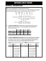
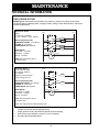
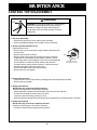
CTASM-00 Control Housings for Tri-Clover Air-Actuated Valves ® Series 761 • 761TR • Butterfly B53 Service & Installation Manual CONTENTS Thank you for purchasing a Tri-Clover Product! This manual contains technical information, disassembly and assembly instructions and complete parts list for all 761 control top module designed and manufactured by Tri-Clover, Inc., Kenosha, Wisconsin. READ THIS MANUAL carefully to learn how to service and reconfigure these control top modules. Failure to do so could result in personal injury or equipment damage. This manual is for standard control top modules. Separate service manuals are available for the Series 761 Valve (761-VSM) and Series B53 Valve (B53) and actuator assemblies. The manuals should be available and referred to when any valve servicing is performed. SAFETY IMPORTANT SAFETY INFORMATION .............................................................................................. 4 INTRODUCTION GENERAL INFORMATION .................................................................................................................. 5 MAINTENANCE TECHNICAL INFORMATION ................................................................................................................ 7 DISASSEMBLY ..................................................................................................................................... 8 ASSEMBLY .......................................................................................................................................... 10 CONTROL TOP FIELD ADAPTATION .............................................................................................. 14 B53 SERIES DISASSEMBLY ............................................................................................................ 15 B53 SERIES ASSEMBLY .................................................................................................................. 16 PARTS LIST .............................................................................................................. 17 -3- SAFETY IMPORTANT SAFETY INFORMATION Safety is very important! DO NOT attempt to modify any Tri-Clover product. To do so could create unsafe conditions and void all warranties. DO NOT place any Tri-Clover product in an application where general product service ratings are exceeded. The following DANGER, WARNING, AND CAUTION signs and their meanings are used within these instructions. DANGER Indicates an imminently hazardous situation which, if not avoided, will result in death or serious injury. The word Danger is used in the most extreme cases. WARNING Indicates a potentially hazardous situation which, if not avoided, may result in minor or moderate injury. May also be used to alert against an unsafe operating or maintenance practice. CAUTION Indicates a potentially hazardous situation which, if not avoided, could result in death or serious injury. SAFETY LABEL below isplaced on every valve with electrical controls. Do not remove any labeling on any Tri-Clover product. Immediately replace any label that is missing. WARNING HAZARDOUS VOLTAGE DISCONNECT POWER BEFORE SERVICING Part Number 38-294 -4- INTRODUCTION GENERAL INFORMATION Make sure you understand the 761 model code before starting! There are seven different sections to a standard part number. Completely identify every section of the part number before attempting to service a control top module. Each valve assembly has its factory original serial and part number printed on an identification label located on the actuator. 761 - 10M - 29L - 2 - 316L - 04 - 4 1 6 4 5 6 7 Valve Type 1 741, 761, 762, 771 Body Style/Port Configuration 2 Refer to Valve Service Manual Actuator Type 3 Refer to Valve Service Manual Size 4 1" through 4" Material 5 316L Switch / Solenoid Option 6 See Chart Below Setup Option 7 See Chart Below The SWITCH / SOLENOID chart identifies what type of electrical components are to be utilized in the control top module. There are three standard solenoid voltages and three different switch/sensors to select from. For any combination there is an option code ranging from 02 through 45. No Solenoid 24VDC 110 VAC 24 VAC Norm Norm Norm Norm Mechanical [VAC/VDC] Quantity 1 02 14 16 39 Quantity 2 04 18 20 40 Proximity [VAC/VDC] Quantity 1 10 30 32 43 Quantity 2 12 34 36 44 --- 37 38 45 No Switches / Solenoid Only 7 3 2 The SET-UP NUMBER SELECTION charts define how the control top module is configured. There are up to seven different ways that it can be setup, but depending upon valve Type and Body Style the operation can differ. Knowledge of the complete valve model is required to choose between the two charts below. Chart A applies to Shut Off or Divert valves and Chart B applies to Reverse Acting and Kettle & Elbow tank outlet valves. Chart B Chart A Set-Up # Actuator Description No Solenoid, normally open or normally closed valve 1 19, 29, 39 No Solenoid, normally open or normally closed valve 1 19 Normally open valve closes when solenoid is deenergized 2 29 Normally closed valve opens when solenoid is deenergized 2 29 Normally closed valve opens when solenoid is deenergized 3 19 Normally open valve closes when solenoid is deenergized 3 29 Normally closed valve opens when solenoid is energized 4 19 Normally open valve closes when solenoid is energized 4 19 Normally open valve closes when solenoid is energized 5 29 Normally closed valve opens when solenoid is energized 5 29, 39 Air both ways, opens when solenoid is energized 6 29, 39 Air both ways, opens when solenoid is energized 7 Actuator Description 19, 29, 39 -5- Set-Up # INTRODUCTION Make sure you understand the B53 model code before starting! There are seven different sections to a standard part number. Completely identify every section of the part number before attempting to service a control top module. Each valve assembly has its factory original serial and part number printed on an identification label located on the actuator. B53 - 6200T - 2 - E - 316 - 04 - 2 1 6 4 3 5 6 7 Valve Type 1 B53 or B53W Actuator Type 2 Refer to Valve Service Manual Size 3 Seat Material Material 4 5 EDPM (E), Silicone (X), Fluoroelastamer FY) 304 (S) or 316 (316) Switch / Solenoid Option 6 See Chart Below Setup Option 7 See Chart Below 1" through 4" The SWITCH / SOLENOID chart identifies what type of electrical components are to be utilized in the control top module. There are three standard solenoid voltages and three different switch/sensors to select from. For any combination there is an option code ranging from 02 through 45. No Solenoid 24VDC 110 VAC 24 VAC Norm Norm Norm Norm Mechanical [VAC/VDC] Quantity 1 02 14 16 39 Quantity 2 04 18 20 40 Proximity [VAC/VDC] Quantity 1 10 30 32 43 Quantity 2 12 34 36 44 --- 37 38 45 No Switches / Solenoid Only 7 2 The SET-UP NUMBER SELECTION chart defines how the control top module is configured. There are three different ways that it can be setup. Description Set-Up # No Solenoid, normally open or normally closed valve 1 Normally open valve closes when solenoid is deenergized 2 Normally closed valve opens when solenoid is deenergized 2 Normally open valve closes when solenoid is energized 5 Normally closed valve opens when solenoid is energized 5 *Note: Butterfly valves regardless of position (normally open or normally closed) operate with the same control set-up. -6- MAINTENANCE TECHNICAL INFORMATION ENCLOSURE RATING NEMA Type 4 - Enclosures are intended for use indoors or outdoors to protect the enclosed equipment against splashing water, seepage of water, falling or hose-directed water, and severe external condensation. Mechanical Switch SPDT 3 amps/125 or 250VAC* 1 /2 amp, 125VDC; 1/4 amp, 250VDC Solenoid Operating Data PRESSURE RANGE: 0 to 120psig** FLUIDS: Air or Inert Gas LUBRICATION: Not Required ELECTRICAL: AC 110/60 - .5.4 Watts AC 24/60 - 7.4 Watts DC 24 - 4.2 Watts Power Com. Upper Switch Solenoid Operating Data PRESSURE RANGE: 0 to 120psig* FLUIDS: Air or Inert Gas LUBRICATION: Not Required ELECTRICAL: AC 120/60 - 5.4 Watts AC 24/60 - 7.4 Watts DC 24 - 4.2 Watts Load Blue White Load Lower**** Switch Brown Yellow Orange Black Purple COIL: General purpose class A, continuous duty. Proximity Sensor*** 2 wire, Normally Open 20-140VAC, 50-60 Hz 10-140VDC 200mA Load Current Max. .8mA Leakage Current Red Load Load Solenoid Power Com. Upper Switch Blue Load Red Lower**** Switch Orange Load Brown Purple Black Solenoid COIL: General purpose class A, continuous duty. Color code represents the cable assembly wires * ** *** **** 3 amps/125Vac max. due to 20 gauge wiring. Supply pressure to any valve/actuator should not exceed 80psig. Other sensor types available, contact Tri-Clover for details. Normally open switch held closed. -7- MAINTENANCE CONTROL TOP DISASSEMBLY WARNING WARNING: To prevent personal injury, disconnect all electrical and pneumatic power to the control top. Hazardous voltage can cause electrical shock. The actuator stem moves with extreme force and suddenness 1. Disconnect the Cable • Unscrew the knurled ring of the cable counter clockwise. • After the threads disengage, pull the cable off of the connector. 2. Remove The Standard Rear Cover Standard Green Cover • Remove the 4 cover screws and o-rings located in the screw hole counter bores. • Remove the electrical connector • Remove each of the wires from the male pins of the connector. Grasp each wire at the base of its terminal connection. Use of needle nose pliers is recommended. Take care not to damage the wire insulation or crimp the terminal. Remove the electrical connector nut by turning counter clockwise. Push the electrical connector through the hole in the rear cover. • Remove the rubber electrical connector gasket. • Remove the rear cover gasket. Base Pull Out Remove wires from the electrical connector. 3. Remove the front cover • Loosen the four cover screws until they disengage their mounting holes in the base. • Remove the cover gasket. 4. Remove the switches NOTE: Not every control top contains switches. Continue to the next step if no switches are present • Where applicable, remove both wire harness connectors from the switches. • Pull the wires through the access hole in the base. • Loosen the switch mounting screws by 2 turns. • Slide the switches and their black mounting blocks completely from the guide tracks in the base. 5. Remove the solenoid NOTE: Not every control top contains a solenoid. Continue to the next step if no soleniod is present. • Pull the two solenoid wires through the access hole. -8- MAINTENANCE • Remove the two mounting screws fastening the solenoid. • Remove the solenoid and triangular selector block located under the solenoid. 6. Remove the control top base from the actuator. • Remove all the air line connections from the base • Remove the three screws from inside the base, and the one bolt outside the base located below the rear cover. • Pull the base straight up and away from the actuator. NOTE: The green bearing retainer might remain attached to the base. It will come out of its counter bore in the base when it hits the activating nut. Be aware that a small amount of impact may be required to dislodge it from the base. -9- MAINTENANCE ASSEMBLY 1. Place the bearing retainer into the counter bore of the actuator. Nut Retainer 2. Place the activating nut onto the stem. NOTE: Remove nylon lock pin, if present, from actuator shaft. NOTE: Do not completely tighten the nut. Leave at least one complete turn for adjustment. 3 3. Place all the seals on the base. • Three o-rings on the bottom of the base. IMPORTANT: When installing the largest diameter o-ring (1), start it in groove opposite the air relief notch and press it in towards the notch. Be careful not to stretch o-ring. • Rear cover gasket. • Pressure relief plug into the hole on the rear of the base above the mounting flange. SETUP OPTIONS 1,2,4 & 6 - COUNTER CLOCKWISE SETUP OPTIONS 3 & 5 - CLOCKWISE • Fasten the housing to the base with three screws and lock washers on the inside and one bolt and a lock washer on the outside. 5. Switch Installation -10- 2 Relief Plug Location 4. Fasten the base to the actuator. IMPORTANT: There are two possible configurations when mounting a control top base to an actuator. The mounting configuration is dependent upon the solenoid set up option. Be sure that the proper setup option number (1 through 6) is known before proceeding. • Orientate the activating nut in relation to the air passage hole as shown in step 1. • Slide the base onto the actuator using the activating nut flats as a guide. • Orientate the control top so the air passage hole is visible through the front mounting hole of the base as illustrated in step 2. • Rotate the base 45 degrees as illustrated in step 3 and described below. All tapped holes should be visible through the base mounting holes. 1 Step 1 Step 2 Air Passage Step 3 Options 3, 5 & 7 Clockwise Counter Clockwise Options 1, 2, 4 & 6 MAINTENANCE IMPORTANT: There are four basic switch mounting configurations. The mounting configurations are dependent upon valve stroke and the installation of either mechanical or proximity switches. Determine the valve stroke (short or long) and what type of switches are being used before continuing. 4" long or "y" body valves • See Mounting Block options for proper switch orientation. Assemble the switches to the mounting blocks as shown at right. Slide the switch(es) into the base mounting tracks. Tighten the switches in a random location. Instructions for proper adjustment are described later. IMPORTANT: Do not over tighten the screws used to mount the switches. • If applicable place the wire harness onto the switch(es). Red, White, Blue - Left switch Orange, Yellow, Brown - Right switch Assembly of switches to the mounting block Mounting Block Options Selector Block Options M P P M Blocked Port M P P M B M P M M M P Left Right Proximity - Short Stroke M P M P P M P P Setup Number 2&3 Left Right Mechanical - Long Stroke Left M Setup Number 4&5 M P P P M P Left Right Mechanical - Short Stroke M P M Right Proximity - Long Stroke Setup Number 6&7 6. Solenoid Selector Block Installation IMPORTANT: The 4 way solenoid mounted into the control top is a single coil, spring return model. It can be configured for top loading, bottom loading or double acting operation. These modes of operation are determined by a triangular selector block located under the solenoid valve. Be sure that the proper setup option (2 through 7) is known before continuing. • • • • See the chart above for proper selector block orientation based upon the setup option. Install all three selector block o-rings. Place the selector block into the base. Pay special attention to its orientation (see below). Place the solenoid on top of the selector block and fasten with two screws. -11- MAINTENANCE 7. Stop Block installation - No Solenoid • Install all four o-rings into the stop block. • Fasten the stop block with two screws. 8. Fasten the wires to the electrical connector Standard Green Cover • Place the rubber gasket over the electrical connector threads. • Push the threaded end of the connector through the hole in the rear cover. • Orientate the connector flange as shown on the inside of the cover and fasten with the connector nut. • Place all the switch and solenoid wires through the access hole in the base. • Follow the wire connection diagram and push the wire terminals over the electrical connector pins. Note: Use of needle nose pliers is recommended. Take care not to damage the wire insulation. Selector Block Orientation - Setup #6 & 7 Inside Rear Cover View 9. Rear Cover Installation Limit Switch Green - Ground Strap Blue - Switch (N.C.) Orange - Switch (N.C.) Red - White (N.O.) Brown - Switch (N.O.) White - Switch (Com.) Black- Solenoid (Either Wire) Yellow - Switch (Com.) Purple - Solenoid (Either Wire) Proximity Switch Green - Ground Strap Blue (Proximity #1) Blue (Proximity #2) Brown (Proximity #1) Brown (Proximity #2) Black- (Optional) (Solenoid - Either Wire) -12- Black- (Optional) (Solenoid - Either Wire) MAINTENANCE • • • • Place the four o-rings into the mounting hole counter bores. Place the mounting screws into the holes. Coil the wires approximately one half turn so that they will fit into the rear cover cavity. The cover can be fastened to the base in any orientation because it is square. 1 4 2 A 3 B C Hole Setup Number Selection Number 1 N.C. 1 N.O. 2 3 4 5 6 7 1 2 B Supply A C B A A C A A Supply Supply Supply Supply Supply Supply 3 4 A A B B B B B B A A A B C A C A 5 Poly Flo Supply B B C C B C C X X X X 5 10. Place the 1/8" NPT air fittings on the housing. • Refer to the reference setup to identify all five of the 1/8 NPT air connection locations. They are labeled 1 through 5. • Identify the air fittings used on each control top. They are labeled A to C. • The Fitting Location chart describes the proper mounting location of the various fittings based upon the seven different setup configurations. An “X” in the Poly-Flo tubing column indicates that 8 to 10 inches of tubing is required for the connection between the two Poly-Flo elbows (C). 11. Actuate the valve and set the switch(s) • Refer to the figure for proper adjustment location on either the Mechanical Switched or Proximity Sensors. Normally open position - Left switch. Open the valve and set the switch as illustrated. Normally closed position - Right switch Close the valve and set the switch as illustrated. Mechanical Switch Proximity Sensor Proper Switch / Sensor Setting 12. Fasten Front Cover • Place gasket into cover • Mount cover with four screws IMPORTANT: The four cover screws must be tightened until the gasket compresses and begins to bulge out the sides. The cover gasket must be sufficiently tightened to seal against spraying liquids. Failure to tighten could result in control top leakage and electrical failure. • Attach the Electrical Cable. Align the guide of the connector with the cable and push them together. Tighten completely by screwing the cable onto the connector. -13- MAINTENANCE CONTROL TOP FIELD ADAPTATION Control top modules can be purchased individually and mounted to almost any 761 Series valve. Included with each control top are all the components necessary to adapt it to a valve / actuator. 761 SERIES CONTROL TOP MODULE NO. 74-100-X-Y For short and long stroke actuators used on standard 1 through 3 inch valves except the Y-body valves. 761 SERIES CONTROL TOP MODULE NO. 74-114-X-Y For extra long stroke actuators used on 4 inch and Y-body valves. 761 SERIES CONTROL TOP MODULE FIELD ADDITION Disassemble the green end cap and stem protector from the actuator (refer to Valve Service Manual 761 VSM-93). Follow the Control Top Assembly instruction in this manual. -14- MAINTENANCE B53 SERIES DISASSEMBLY B53 SERIES CONTROL TOP MODULE 1. Remove the actuator from the mounting bracket. Push Tool Plate 2. On air to air models, slide the outer retaining ring up the end cap so it is no longer locking the end cap from going into the actuator. A press will not be required to remove the split wire. 3. Remove the control top front cover. Locate the push tool on the control top as shown on right. Place the actuator in a manual press with the ram rod centered on the push tool. The coupler must be free to rotate. 4. Push the mounting adapter into the cylinder until the split wire retaining ring is accessible. Push Tool Location 5. Remove the split wire retaining ring from its groove. 6. Release press ram slowly until the springs stop pushing. On spring assist actuators, the piston, mounting adapter, and control top will rise approximately one inch above the cylinder before the springs reach free length. 7. Remove the components from inside the actuator. 8. Separate the control top from the mounting adapter, and remove the indicating nut from the rising stem. 9. Remove the bushing and packing by sliding the mounting adapter off the rising stem. 3 / 1 4 37/8 5 /16 - 18 Threaded Rod Typical 2 places 4 31/8 / - 18 Drill & Tap Typical 2 places Push Tool Details 5 16 -15- MAINTENANCE B53 SERIES ASSEMBLY B53 SERIES CONTROL TOP MODULE 1. Lubricate and install all the o-rings on the piston, mounting adapter and drive shaft. 2. Lubricate and install all the roller and thrust bearings. 3. Remove the control top front cover. 4. Slide the mounting adapter over the rising stem. 5. Install the vee packing and bushing. Refer to illustration at right and follow the steps below. • Cover the rising stem threads with tape. • Slide the new packing over the stem with the "v" side facing the piston. • Partially insert the packing into the smallest counter bore using a flat tool to assist the outer lip. • Push the packing into its counter bore by pushing the bushing into place. 6. Install the indication nut onto the rising stem. 7. Fasten the control top module to the mounting adapter. 8. Place the piston/control top assembly in the cylinder aligning all bearings with all piston grooves. IMPORTANT - All the bearings must be aligned with the grooves in the cylinder. 9. Place actuator in a manual press. Locate the push tool as shown on the previous page. Air to air models do not require a press. 10. Center the press ram on the push tool and depress the piston/control top assembly into the cylinder. IMPORTANT - Press the assembly slowly and with minimal force. If the assembly does not descend into the cylinder, realign the bearings with the piston grooves. 11. Depress the assembly into the cylinder until the split wire retaining ring can be located in its groove. Lock the press in this position. 12. Install the split wire retaining ring. 13. Release the press and let the assembly rise until the mounting adapter stops on the split wire retaining ring. 14. On air to air models, slide the retaining ring down into the retaining ring groove. This ring is required to prevent the end cap from falling into the actuator. -16- Retaining Ring Wire Ring End Cap O-Ring Piston O-Ring PARTS LIST How to order replacement parts All orders for repair parts must contain the following data: 1. Complete model number (from name plate). 2. Serial number (from name plate). 3. Key number and description. The following exploded view and accompanying parts list facilitate order repair parts from the factory. All parts list illustrated are indexed to the parts list by key numbers. Key # Description Part Number 1 2 3 4 5 6 6A 7 8 9 10 11 12A• 12B• Base O-Ring O-Ring O-Ring Packing Retainer Stem Guide (Limit Switch) Stem Guide (Proximity Switch) Screw Screw Lockwasher Mounting Block Spacer Block Micro Switch Proximity Switch (with harness) Proximity Switch - std.(without harness) Screw Screw (4" only) Left Wire Harness Right Wire Harness O-Ring Stop Block (w/o solenoid) Screw (w/o solenoid) Plug Selector Block (w/solenoid) 24 VDC Solenoid 1-36 17-109-U 17-35-U 17-63-U 25-428-04 36-82A 36-94 SC1307E-SS SC1308H-SS LWA1300-SS 54-100 54-101 EL-79500-0013 EL-79500-0030 1 1 1 1 1 1 1 3 1 1 1 or 2 1 or 2 1 or 2 1 or 2 EL-79500-0040 1 or 2 SC108R-SS SC105H-SS EL-97750-0048 EL-97750-0049 17-344-U 54-99 SC505R-SS 14-124 54-98 33-171A 2 or 4 3 1 or 2 1 or 2 3 or 4 1 2 1 or 2 or 3 1 1 12C• 13 13A 14L* 14R* 15 16 17 18 19 20A• -17- Quantity PARTS LIST Key # Description Part Number Quantity 20B• 20C• 21 22 23 24 110 VAC Solenoid 24 VAC Solenoid Screw (w/ solenoid) Vent Plug Poly-Flo Elbow Poly-Flo (Normally Closed Valve) Electrical Connector Rear Cover Gasket O-Ring Back Cover Screw Screw Front Cover Gasket Cover Screw Cable Assembly Pressure Relief Circuit Board Cable Clamp (4" only) Base Extension Spacer Block Screw Wire Harness Lockwasher Ground Strap Stem Adapter (1" only) 33-169A 33-170A SC512F-SS MS-105-58A-CP 42-76-9 41-6 1 1 2 1 1 1 EL-19600-0087 17-340B-E 17-139-U-90 44-251B SC107R-SS SC110R-SS 17-337B-E 1-37 SC707R-SS EL-97515-0058 17-348 EL-11100-0002 16-115 1-38 54-115 SC108R-SS EL-97750-0047 LWA100-SS EL-97750-0060 36-87-S 1 1 4 1 4 4 1 1 4 1 1 1 1 1 1 1 1 3 1 1 26 27 29 30 31 34 35 36 37 38 40 41 42 43 44 45 46L 47 48 49 • * - It is recommended that one of each of the items be stocked as spare parts. Required when using 12A or 12B. Items 42 through 47 are for control housings used with a stroke longer than 2 inches. Item 42 not shown. This manual is for standard control top modules. Separate service manuals are available for the Series 761 Valve (761-VSM) and Series B53 Valve (B53) and actuator assemblies. The manuals should be available and referred to when any valve servicing is performed. -18- PARTS LIST 46L If No Solenoid 45 21 17 16 44 20A 14L 10 13A 47 15 4" & "y" body valves 11 13 36 8 7 10 12A 9 37 19 15 35 29 31 30 43 26 27 26 1 38 2 3 33 35 4 6 39 5 18 22 Satttop Unit 23 -19- Tri-Clover manufactures a complete line of TRI-WELD® fittings TRI-CLAMP® fittings BEVEL SEAT fittings POSITIVE PUMPS CENTRIFUGAL PUMPS AUTOMATIC Air Actuated VALVES STAINLESS STEEL TUBING AUTOMATED FLOW CONTROL SYSTEMS Terms, Warranty Provisions, Notice of Claims and Limitation of Liability Prices and all terms and conditions of sale are established in current price sheets and are subject to change without notice. All orders are subject to acceptance by Tri-Clover Inc. at its Kenosha, Wisconsin or Distribution Center* offices only. No assignment of the purchasers rights may be made without consent of Tri-Clover Inc. Each Tri-Clover item is warranted to be free from manufacturing defects for a period of one (1) year from the date of shipment, providing it has been used as recommended and in accordance with recognized piping practice, and providing it has not been worn out due to severe service, such as encountered under extremely corrosive or abrasive conditions. This warranty is expressly in lieu of any other warranties, express or implied, including but not limited to, any implied warranty of merchantability or fitness for a particular purpose. All claims must be in writing and must be mailed or delivered by purchaser within thirty (30) days after purchaser learns of the facts upon which such claim is based. Any claim not made in writing and within the time period specified above shall be deemed waived. Purchasers sole and exclusive remedy and Tri-Clover Inc.s maximum liability for claims arising hereunder or for negligence for any and all losses and damages resulting from any cause shall be either the repair or replacement of defective items or, at Tri-Clover Inc.s option, the refund of the purchase price for such items. In no event, including in the case of a claim for negligence, shall Tri-Clover be liable for incidental or consequential damages including loss of profits. No person, including any representative, employee or agent of Tri-Clover, is authorized to assume on behalf of Tri-Clover Inc., any liability or responsibility in addition to or different from that described in this provision. Any and all representations, promises, warranties or statements that are in addition to or different from the terms of this provision are of no force or effect. *Distribution Center in Union City, California Tri-Clover Tri-Clover P.O. Box 1413 Kenosha, Wisconsin 53141-1413 PHONE: 262-694-5511 FAX: 262-694-7104 E-Mail address: [email protected] Visit our web site at www.tri-clover.com ©2000 Tri-Clover CTASM 2M 08/00